Advertisement
Quick Links
Advertisement

Summary of Contents for Cisco Meraki MR84
- Page 1 Meraki MR84 Hardware Installation Guide...
-
Page 2: Table Of Contents
Trademarks Cisco, Cisco Meraki, Meraki, Meraki MR84, and Meraki Cloud Controller are trademarks of Cisco Systems, Inc. Other brand and product names are registered trademarks or trademarks of their respective holders. Warranty Cisco Systems, Inc. provides a one year warranty on this product. Warranty details may be found at www.meraki.cisco.com/support. -
Page 3: Scope Of Document And Related Publications
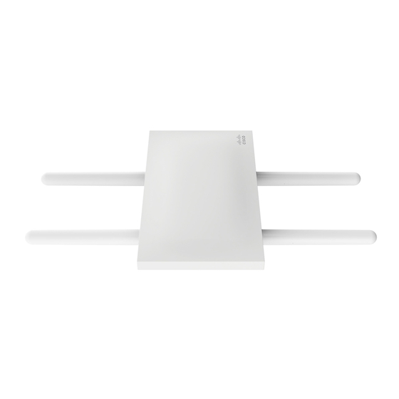
- Mounting straps 2.2 Antennas and Ports The Meraki MR84 has two radios. Each radio has two external antenna connectors; both connectors for a particular radio should be attached to the same type of antenna. The 5 GHz radio is used for mesh or client communication. -
Page 4: Pre-Install Preparation
The Meraki MA-ANT-20 omni-directional antennas must be installed vertically. The Meraki MA-ANT-25 patch antenna, MA-ANT-27 dual-band sector antenna, and Cisco AIR-ANT2513P4M-N stadium antenna must be installed facing downward, at least 30 degrees from the horizon line. 2.3 Power Source Options The MR84 access point can be powered using either an 802.3at capable... - Page 5 MR84 to your network. For detailed instructions about creating, configuring and managing Meraki wireless networks, refer to the Meraki Cloud Controller Manual (cisco.meraki.com/support/#documentation). 1. Login to http://dashboard.meraki.com. If this is your first time, create a new account.
- Page 6 3.3 Check and Configure Firewall Settings If your network will be located behind a firewall, it must allow outgoing connections on particular ports to particular IP addresses in order for the MR84 to be able to seamlessly communicate with the Cloud Controller. The most current list of outbound ports and IP addresses can be found here: http://bit.ly/oZpMQ7 3.4 Assigning IP Addresses to MR84s...
-
Page 7: Installation Instructions
servers that this AP will use on its wired connection. 5. If necessary, reconnect the AP to the LAN. 3.5 Collect Tools You will need the following tools to perform an installation: - Flat-head screwdriver - Drill with appropriate bits for mounting wall anchors (if mounting to a wall) - Phillips screwdriver Tin snips (if mounting with hose clamps) - Power screwdriver with 5/16”... - Page 8 Meraki devices. For more detailed instructions regarding access point location selection, reference the Meraki Network Design Guide (cisco.meraki.com/support/#documentation). 4. The antennas should be as unobstructed as possible. Make sure that there is clearance around the MR84 for installation of all of your chosen antennas.
- Page 9 It is recommended that the MR84 be mounted to a wall or solid ceiling using the mount plate for physical security reasons. 4.2.2.2 Pole Mount Using Mount Plate Use the included mounting straps to mount the AP to a pole less than 3.9” in diameter.
- Page 10 MR84. 3. Install a cable gland on the MR84 end of the cable. 4. Plug the Ethernet cable into the Ethernet port of the Meraki MR84. a. Connect the cable to the Ethernet port on the MR84. b. Screw the gland body into the threaded hole of the port. Use an adjustable wrench to make sure the gland body is fully seated in the hole.
-
Page 11: Troubleshooting
5 Troubleshooting Reference the Meraki knowledge base at http://meraki.com/support/#kb for additional information and troubleshooting tips. 6 Regulatory FCC Compliance Statement This device complies with part 15 of the FCC rules. Operation is subject to the following two conditions: (1) This device may not cause harmful interference, and (2) this device must accept any interference received, including interference that may cause undesired operation. - Page 12 This equipment complies with FCC radiation exposure limits set forth for an uncontrolled environment. This equipment should be installed and operated with minimum distance 27.5 cm between the radiator and your body. This transmitter must not be co-located or operating in conjunction with any other antenna or transmitter.
- Page 13 LAN-EL. Industry Canada Radiation Exposure Statement This equipment complies with IC radiation exposure limits set forth for an uncontrolled environment. This equipment should be installed and operated with minimum distance 27.5 cm between the radiator & your body. Déclaration d’exposition aux radiations Cet équipement est conforme aux limites d’exposition aux rayonnements IC établies pour un environnement non con trôlé.


