Advertisement
MR56 Installation Guide
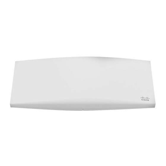
The Cisco Meraki MR56 are dual-band enterprise class 802.11ax cloud-managed access points. Designed for highest capacity and highest density, the
MR56 meets the needs of the most demanding environments. The access point also includes a third radio dedicated to optimizing the RF environment
and securing the airwaves.
About this Guide
This guide provides instruction on how to install and configure your MR56 access points. This guide also provides mounting instructions and limited
troubleshooting procedures. For more wireless installation guides, refer to the
Product Overview
Physical Specifications
Interfaces
•
1x 1000/2.5G/5G BASE-T Ethernet (RJ45)
•
1x DC power connector (5.5 mm x 2.5 mm, center positive)
Power
•
Power over Ethernet: 42.5 - 57 V (802.at compliant)
•
Alternative: 12 V DC input
•
Power consumption: 22W max (802.3at)
•
Power over Ethernet injector and DC adapter sold separately
Environment
•
Operating temperature: 32 °F to 104 °F (0 °C to 40 °C)
•
Humidity: 5 to 95% non-condensing
Physical Security
•
Two security screw options (included) (3.5 mm long and 2.5 mm diameter and 5 mm
head)
•
Kensington lock hard point
MR56
wireless installation guides section
on our documentation website.
1
Advertisement
Table of Contents

Related Manuals for Cisco Meraki MR56


Summary of Contents for Cisco Meraki MR56
- Page 1 MR56 Installation Guide The Cisco Meraki MR56 are dual-band enterprise class 802.11ax cloud-managed access points. Designed for highest capacity and highest density, the MR56 meets the needs of the most demanding environments. The access point also includes a third radio dedicated to optimizing the RF environment and securing the airwaves.
- Page 2 • Concealed mount plate with anti-tamper cable bay Product View and Physical Features Your MR56 has the following features:...
- Page 3 The mount cradle has the following features:...
- Page 4 Security Features The MR56 features multiple options for physically securing the access point after installation: Security screw – The accessory kit includes screws that can be used to secure the access point to the mount cradle. Engaging the security screw prevents accidental dislodging and theft.
- Page 5 The port labeled “PoE” accepts 802.3at and 802.3af power and should be used as the primary uplink to your LAN/WAN. Power Source Options The MR56 access point can be powered using either the Meraki AC Adapter, PoE Injector (both sold separately), or a third-party PoE switch. Factory Reset Button If the button is pressed and held for at least five seconds and then released, the AP will reboot and be restored to its original factory settings by deleting all configuration information stored on the unit.
- Page 6 Mount cradle including built-in level tool Drop ceiling mount kit...
- Page 7 Wall screws, wall screw anchors, and security screws...
- Page 8 Safety and Warnings These operations are to be taken with respect to all local laws. Please take the following into consideration for safe operation: • Power off the unit before you begin. Read the installation instructions before connecting the system to the power source.
-
Page 9: Pre-Install Preparation
Pre-install Preparation You should complete the following steps before going on-site to perform an installation. Configure your Dashboard Network The following is a brief overview only of the steps required to add an access point to your network. For detailed instructions about creating, configuring and managing Meraki wireless networks, refer to the online documentation (documentation.meraki.com). - Page 10 • Using a client machine (e.g., a laptop), connect to the AP wirelessly (by associating to any SSID broadcast by the AP) or over a wired connection. • If using a wired connection, connect the client machine to the AP either through a PoE switch or a PoE Injector. If using a PoE switch, plug an Ethernet cable into the AP’s Ethernet jack, and the other end into a PoE switch.
-
Page 11: Installation Instructions
2. Power over Ethernet supports a maximum cable length of 300 ft (100 m). 3. If being used in a mesh deployment, the AP should have line of sight to at least two other Meraki devices. A Cisco Partner can help ensure that your AP placement is ideal. - Page 12 The mount cradle contains a variety of hole patterns that are customized for each installation scenario. The mounting template (included inbox with mount cradle) should be used to drill holes for wall mounts and also to identify the correct hole patterns in the mount cradle that should be used for each type of mount. The included mount cradle template shows the hole patterns that should be used for each type of mount.
- Page 13 1. Attach the T-rail clips to the T-rail by rotating them and snapping them into place as shown. The black foam pads should be compressed slightly after installation. 2. Using the dashed lines on the mount cradle template as a guide, set the proper spacing of the T-rail clips on the T- rail.
- Page 14 4. Attach the mount cradle to the T-rail clips using the mount cradle holes (marked with a “T“). Tip: Pre-assemble rubber spacers and screws to the mount cradle. The mount cradle can then be held with one hand while the other hand holds a screwdriver. If mounting your AP to a dropped ceiling, skip to the "Power the AP"...
- Page 15 Then adjust the MR56 AP to guide the AP’s bottom slot into the cradle’s bottom tab until it clicks into place. Once in place, the MR56 AP should be secured to the cradle by using one of the included screws in the cradle’s bottom tab.
-
Page 16: Verify Device Functionality And Test Network Coverage
To release the AP from the mount cradle, first remove the security screw that secures the MR56 AP to the cradle’s bottom tab. While holding the MR56 AP with one hand, press the cradle’s bottom tab upwards, releasing the MR56 AP from the bottom of the cradle. Then remove the MR56 AP from the cradle’s top tab. Desk or Shelf Mount The access point can both be placed on a desk or shelf resting on the non-scratch rubber feet. -
Page 17: Basic Troubleshooting
automatically upgrading and the LED should turn green when the upgrade is completed (normally within a few minutes). See the "LED Indicators" section for more details. . b. Note: Your AP must have an active route to the Internet to check and upgrade its firmware. 2. -
Page 18: Warranty
If you are still experiencing hardware issues, please contact Cisco Meraki support by logging in to dashboard and using the Help option near the top of the page, then opening and email case or calling using the contact information on that page. - Page 19 Meraki MR56 devices have been tested and found to comply with the limits for a Class B digital device, pursuant to part 15 of the FCC rules. These limits are designed to provide reasonable protection against harmful interference in a residential installation. This equipment generates, uses and can radiate radio frequency energy and, if not installed and used in accordance with the instructions, may cause harmful interference to radio communications.