Table of Contents
Advertisement
Quick Links
Alarm model:
...........................................................................
Sold on:
...........................................................................
By:
I nstalled on bike
model, number
GEMINI Technologies S.r.l.
Via Luigi Galvani 12 - 21020 Bodio Lomnago (VA) - Italy
Tel. +39 0332 943211 - Fax +39 0332 948080
www.gemini-alarm.com
ISO 9001 Certified company
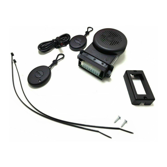
952N
USER AND INSTALLER
MANUAL
UK
Made in Italy
REV.02 - 09/17
Advertisement
Table of Contents

Related Manuals for Gemini 952N


Summary of Contents for Gemini 952N
- Page 1 I nstalled on bike model, number 952N USER AND INSTALLER MANUAL GEMINI Technologies S.r.l. Via Luigi Galvani 12 - 21020 Bodio Lomnago (VA) - Italy Tel. +39 0332 943211 - Fax +39 0332 948080 www.gemini-alarm.com Made in Italy ISO 9001 Certified company...
-
Page 2: Table Of Contents
CONTENTS CONTENTS - INTRODUCTORY NOTE INSTALLER MANUAL USER MANUAL 15.0 FITTING INSTRUCTIONS - ALARM SYSTEM CONTROL DEVICES 16.0 - ALARM UNIT SEALING - SYSTEM OPERATION - BASIC CONFIGURATION 17.0 - ALARM UNIT POSITIONING 3.1 - Arming 18.0 - ACCESSORIES - FITTING 3.2 - Top case/seat open warning 18.1 - Status LED 3.3 - Arming delay... -
Page 3: Introductory Note
The remote control has 2 buttons that activate several functions based on the The 952N alarm system cannot be paired with transponder alarm configuration: TAG 908. Button 1 •... -
Page 4: System Operation - Basic Configuration
3.6 - ARMED CONDITION 3.0 - SYSTEM OPERATION - BASIC CONFIGURATION After the 20 sec. arming delay, the system is fully armed and ready to detect 3.1 - ARMING any irregularity. The LED will start flashing to confirm the armed condition. To arm the system, press remote control button “1”. -
Page 5: System Disarming Without Alarm Memory
3.10 - SYSTEM DISARMING WITHOUT ALARM MEMORY 4.1 - OPTICAL/ACOUSTIC SIGNALS To disarm the system, press remote control button “1”. The status LED will turn Operations such as arming/disarming, system programming, alarm memory OFF and disarming will be confirmed by 3 Beeps and 3 flashes of the turn and learning new devices are signaled both acoustically and optically (LED indicators. -
Page 6: Self-Rearming
4.5 - ANTI-HIJACK FEATURE 5.0 - SLEEP MODE - ENERGY SAVER FEATURE To activate the anti-hijack feature while the engine is running, either: In order to preserve battery life, the system will automatically revert to sleep Press remote control button “1”. mode when the vehicle is sitting idle for a period of time. -
Page 7: Pin Code Override
7.0 - PIN CODE OVERRIDE 8.0 - PIN CODE OVERRIDE EXAMPLE If you cannot disarm the system from the remote controls because they are lost To help you understand the override procedure by PIN code, here below is a or broken or batteries are flat, you will be able to disarm the system by using the step-by-step example entering PIN code “2-3-4-1”. -
Page 8: Pin Code Customization
9.0 - PIN CODE CUSTOMIZATION Simultaneously press both remote control buttons. The LED will turn OFF Here below is a step-by-step example showing how to customize the factory PIN code. In this case the selected PIN code is 2-3-4-1 isarm the alarm system Ground the BROWN-GREEN wire. -
Page 9: Replacing Remote Control Batteries
Do not use voltages other than the one specified by the manufacturer Protect the alarm from any direct water flow such as high-powered water jets found in a car wash. BATTERIES ATTENTION Gemini Technologies will not be held responsible for any damage caused by improper use. WARNING Use only CR1616 batteries. -
Page 10: Installer Manual
INSTALLER MANUAL 17.0 - ALARM UNIT POSITIONING Since the alarm has a built-in high sensitivity triaxial sensor, it can be positioned 15.0 - FITTING INSTRUCTIONS either vertically or horizontally as long as you keep the following in mind Please read all instructions and understand them thoroughly before starting the installation. -
Page 11: Status Led
18.0 - ACCESSORIES CAUTION Alarms are supplied without wiring harnesses. A wide range of specific pin- 18.1 - STATUS LED to-pin wiring harnesses is available for the most common motorbikes. Since the LED warning light serves as both a system status indicator and a The following tables refer to the generic wiring harness KITCA 417N17. -
Page 12: Wiring Diagram
20.0 - WIRING DIAGRAM 21.0 - IMMOBILIZER WIRING DIAGRAM ENGINE IMMOBILIZER - GROUNDED WIRE For most small 2-stroke motorcycle engines. White White/Grey Ground Key switch Immobilizer wire Orange Turn indicators Orange To vehicle engine (12V) Status Seat/topcase ENGINE IMMOBILIZER - CUT WIRE contact switch (recommended) Green-Brown... -
Page 13: Diode Installation
22.0 - DIODE INSTALLATION Turn ignition key in ON. 2 flashes of the turn indicators and 2 confirmation tones (1 Bop and 1 How to tell if you need to install a diode: Beep) will acknowledge the system is in learn mode. Activate one of the turn indicators, turn ignition key OFF and arm the alarm. -
Page 14: Programmable Features
After pressing both buttons simultaneously (step 4), program the features 24.0 - PROGRAMMABLE FEATURES according to your needs. To either enable or disable one of the programmable features, proceed as follows: TO ENABLE TO DISABLE NB: Remember to ALWAYS arm/disarm the system before programming. Press button 1 Press button 2 With the system disarmed, lift the seat... -
Page 15: Programming Example
26.0 - TILT SENSOR ADJUSTMENT 25.0 - PROGRAMMING EXAMPLE Here below is a step-by-step example showing how to program the system The alarm system has a built-in triaxial tilt/shock sensor with 4 levels of with the acoustic signals, the panic alarm and the pre-alarm features enabled. sensitivity adjustment. - Page 16 R&TTE Declaration of Conformity NOTES Doc ref. No. 2010-01 We, the undersigned, Company GEMINI TECHNOLOGIES S.r.l Address, City Via Luigi Galvani 12, 21020 Bodio Lomnago (VA) Country Italy Phone number +39 0332 943211 Fax number +39 0332 948080 Declare under our sole responsibility that the following equipment:...