ADTRAN Total Access 3000 Installation And Maintenance Manual
Ds0 time slot interchange multiplexer
Hide thumbs
Also See for Total Access 3000:
- System manual (511 pages) ,
- Installation and maintenance practice (40 pages) ,
- Installation and maintenance manual (32 pages)
Table of Contents
Advertisement
Quick Links
CONTENTS
1.
GENERAL ............................................................................. 1
2.
INSTALLATION ................................................................... 2
3.
OPERATION ......................................................................... 3
4.
MENU STRUCTURE ............................................................ 7
5.
SPECIFICATIONS .............................................................. 17
6.
MAINTENANCE ................................................................ 17
7.
WARRANTY AND CUSTOMER SERVICE .................... 18
Appendix A. Alarm List ............................................................ A-1
FIGURES
Figure 1. Total Access 3000/3010 DS0 TSI-MUX .................. 1
Figure 2. TSI-MUX Menu Tree ................................................ 8
Figure 3. TSI-MUX Main Menu Screen ................................... 9
Figure 4. Configuration Menu Screen ....................................... 9
Figure 5. Provisioning Screen ................................................. 10
DS0 Mapping ............................................................ 11
DS0 Tapping ............................................................. 11
In-Band Management Main Menu ........................... 12
HSMC Statistics Menu ............................................. 13
Figure 10. Channel 1 Menu ........................................................ 13
Figure 11. Status Menu Screen .................................................. 14
Figure 12. Test Menu Screen ..................................................... 15
Figure 13. Performance Monitoring Screen .............................. 15
Figure 14. Protection Configuration Screen .............................. 16
Figure 15. Display Options ........................................................ 16
TABLES
LED Indicator Descriptions ........................................ 3
Switch Descriptions .................................................... 4
DS0 TSI-MUX Specifications .................................. 17
Table A-1. Alarm List ............................................................... A-1
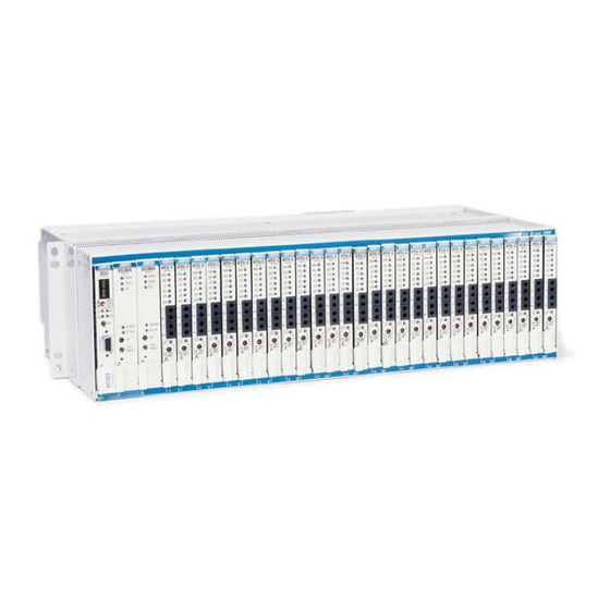
1. GENERAL
This practice is an installation and maintenance guide
for the ADTRAN Total Access 3000/3010 TSI-MUX
illustrated in Figure 1.
Revision History
This is the initial release of this document. Future
revisions to this document will be explained in this
subsection.
NOTE
The Total Access 3000 is a 23-inch chassis with
one SCU slot, two multiplexer slots, and 28
access module slots. The Total Access 3010 is
a 19-inch chassis with one SCU slot, two
multiplexer slots, and 22 access module slots.
References to common, but differing, parameters
61182022L1-5A
All manuals and user guides at all-guides.com
®
Total Access
3000/3010 DS0 Time Slot
Interchange Multiplexer
Installation and Maintenance
Trademarks: Any brand names and product names included in this document are trademarks,
Section 61182022L1-5, Issue 1
registered trademarks, or trade names of their respective holders.
DS0TSIMX
Figure 1. Total Access 3000/3010 DS0
TSI-MUX
between the Total Access 3000 and the Total
Access 3010, such as number of slots, will be
conveyed by the convention a/b. The "a"
represents the Total Access 3000 parameter and
the "b" represents the Total Access 3010
parameter. For example, the differing number
of access slots in the two platforms, 28 for the
Total Access 3000 and 22 for the Total Access
3010, would be displayed "28/22."
Features
The Total Access DS0 TSI-MUX Module (hereafter
referred to as TSI-MUX), P/N 1182022L1, includes
the following features:
• Supports programmable time slot assignment of
the tributary channels (E1) to the access slots
• Local or External timing modes
• Provides 1:1 equipment MUX protection
switching
• Supports field upgrades of firmware
• Operation over a standard temperature range of
-40°C to +65°C
Section 61182022L1-5A
Issue 1, September 2002
1182022L1
POWER
STATUS
TEST
LOCKOUT
ON LINE
APS
TEST/
ENABLE
1
Advertisement
Table of Contents

Related Manuals for ADTRAN Total Access 3000


Summary of Contents for ADTRAN Total Access 3000
-
Page 1: Table Of Contents
MAINTENANCE ..............17 WARRANTY AND CUSTOMER SERVICE ....18 Appendix A. Alarm List ............A-1 FIGURES Figure 1. Total Access 3000/3010 DS0 TSI-MUX ....1 LOCKOUT Figure 2. TSI-MUX Menu Tree ..........8 ON LINE Figure 3. TSI-MUX Main Menu Screen ........9 Figure 4. -
Page 2: Installation
TSI-MUX, the unit will be provisioned to factory The DS0 TSI-MUX plugs directly into the Total default settings. These settings are: Access 3000/3010 shelf. The Total Access 3000/3010 chassis is rack mounted, with a System Controller MUX Service State Out Of Service,... -
Page 3: Operation
SCU, the provisioning of the last occupant of enough mapping capability to map 56 E1 signals to the MUX slot, including Service State, will be another 56 E1 signals within a Total Access 3000 written to the new MUX upon installation, given that shelf. -
Page 4: Table 2. Switch Descriptions
64 kbps (DS0) channels. enough mapping capability to map 56 E1 signals to Loopbacks can be initiated on any time slot that is another 56 E1 signals within a Total Access 3000 mapped. The loopback temporarily overwrites any shelf. - Page 5 All manuals and user guides at all-guides.com Mode 2 Pattern Loss Seconds This inserts an E1 framed 2 -1 pattern into the 64 The pattern loss seconds count represents the number kbps (DS0) data stream toward the Access Modules. of seconds since the first synchronization of the test The definition of this test pattern is defined in ITU pattern when the pattern has been lost.
- Page 6 All manuals and user guides at all-guides.com integration function has a criteria to clear of 10.0s ± Errored Seconds 0.5s of a persistent clear condition. The errored seconds count represents the number of seconds with at least one bit error since the first Fault Alarms synchronization of the test pattern.
-
Page 7: Menu Structure
Protection Switching the TSI-MUX. A menu tree is provided in Figure 2 to The Total Access 3000/3010 shelf provides the be used as an aid in navigating the menus. All menus capability for two TSI-MUX cards to be configured in are generated by the TSI-MUX, and are accessed via a redundant mode. -
Page 8: Figure 2. Tsi-Mux Menu Tree
All manuals and user guides at all-guides.com Section 61182022L1-5, Issue 1 61182022L1-5A... -
Page 9: Figure 3. Tsi-Mux Main Menu Screen
Information such as software revision will change and reflect the new software as the upgrades are performed. Shelf: Slot: Total Access System 08/08/02 15:47 Unacknowledged Alarms: Active Adtran TSI DS0 Mux Configuration Provisioning Inband Management Status Alarms Test Performance Monitoring Protection Configuration... -
Page 10: Figure 5. Provisioning Screen
All manuals and user guides at all-guides.com Provisioning Menu Out Of Service, Unassigned Figure 5 represents the TSI-MUX Provisioning The Out Of Service, Unassigned state is the inactive screen. This screen allows users to make provisioning configuration state of the TSI-MUX. Data processing changes to module performance parameters. -
Page 11: Figure 6. Ds0 Mapping
TSI-MUX automatically. upload utilizes either the craft or administration ports These limits can change dynamically as access control by the Total Access 3000/3010 System modules are configured, inserted, or removed. Controller Unit. The firmware upload contains software version and CRC-32 information to verify the firmware image that is being uploaded. -
Page 12: Figure 8. In-Band Management Main Menu
All manuals and user guides at all-guides.com Reboot Into New software In-Band Management Menu Activation of a new firmware upgrade is performed Figure 8 represents the TSI-MUX In-band through a soft reset. The reset command is available Management Menu screen. This screen allows user through an SNMP operation as well as a menu item access to view status information for the High Speed upon successful completion of a firmware upgrade. -
Page 13: Figure 9. Hsmc Statistics Menu
All manuals and user guides at all-guides.com The TSI-MUX allows for the provisioning of one TSI-MUX and the SCU. In PPP mode, the TSI-MUX in-band management channel. This channel may run will negotiate a PPP session before sending traffic in either Transparent or Point-to-Point Protocol (PPP) over the HSMC. -
Page 14: Figure 11. Status Menu Screen
All manuals and user guides at all-guides.com Status Menu NOTE Figure 11 represents the TSI-MUX Status Menu. This is not an alarm history log. All alarms are This screen is read only and gives the user status logged into an alarm history buffer within the information. -
Page 15: Figure 12. Test Menu Screen
All manuals and user guides at all-guides.com Unassigned” states, the user is recommended to Test Menu perform the loopbacks in the “Out Of Service, Figure 12 represents the TSI-MUX Test Menu. This Maintenance” state. screen allows the user to perform various loopback tests. -
Page 16: Figure 14. Protection Configuration Screen
All manuals and user guides at all-guides.com Protection Configuration Menu NOTE Figure 14 represents the TSI-MUX Protection Far-end Performance Monitoring is available in Configuration Menu. This screen allows the user to C-BIT framing mode only. perform a manual switch to the OffLine MUX. A manual switch overrides the APS status of INHIBIT. -
Page 17: Specifications
Table 3. ADTRAN cautions against performing repairs in the field. Repair services are available if you return damaged units to ADTRAN. Refer to the Warranty and Customer Service section of this Practice. Table 3. DS0 TSI-MUX Specifications . n i . -
Page 18: Warranty And Customer Service
All manuals and user guides at all-guides.com 7. WARRANTY AND CUSTOMER SERVICE Asia Pacific - Beijing, China 8610 8857 6415 voice ADTRAN will replace or repair this product within 8610 8857 6417 fax five (5) years from the date of shipment if it does not sales.china@adtran.com meet its published specifications or fails while in service. -
Page 19: Appendix A Alarm List
All manuals and user guides at all-guides.com Appendix A Alarm List The section column refers to the section number within ANSI T1.231-1997. All parameter alarms are referenced to the parameter section of this specification. The diagnostic alarms are referenced to the diagnostic section of this specification. - Page 20 All manuals and user guides at all-guides.com Section 61182022L1-5, Issue 1 61182022L1-5A...