ADTRAN Total Access 3000 Installation And Maintenance Practice
4-pair line power unit
Hide thumbs
Also See for Total Access 3000:
- System manual (511 pages) ,
- Installation and maintenance practice (40 pages) ,
- Installation and maintenance manual (32 pages)

Related Manuals for ADTRAN Total Access 3000


Summary of Contents for ADTRAN Total Access 3000
- Page 1 1181500L2 POWER UNDER VOLTAGE GROUND FAULT OVERLOAD UNDER CURRENT ® Total Access 3000/3010 4-Pair Line Power Unit Installation and Maintenance Practice Document Number: 61181500L2-5B CLEI: SIPQ0CTF_ _ April 2007...
- Page 2 In no event will ADTRAN be liable for any special, incidental, or consequential damages or for commercial losses even if ADTRAN has been advised thereof as a result of issue of this document.
- Page 3 Revision History Revision Date Description August 2005 Initial Release April 2007 Second Issue. Updated product description. Conventions The following typographical conventions are used in this document: This font indicates a cross-reference link. indicates screen menus, fields, and parameters. This font indicates keyboard keys ( ).
- Page 4 Total Access 3000/3010 4-Pair Line Power Unit Installation and Maintenance Practice Training ADTRAN offers training courses on our products. These courses include overviews on product features and functions while covering applications of ADTRAN product lines. ADTRAN provides a variety of training options, including customized training and courses taught at our facilities or at customer sites.
-
Page 5: Table Of Contents
Logging on to the Total Access 3000/3010 ........ - Page 6 ADTRAN Technical Support ........
-
Page 7: General
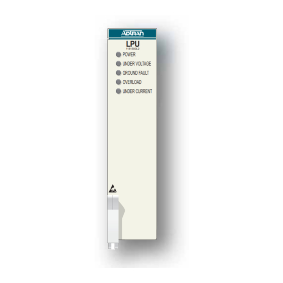
Total Access 3000/3010 4-Pair Line Power Unit GENERAL This practice is an installation and maintenance guide for the ADTRAN Total Access ® 3000/ 3010 4-Pair Line Power Unit (LPU). Figure 1 illustrates the LPU (P/N 1181500L2) front panel. 1181500L2 POWER... -
Page 8: Description
Total Access 3000/3010 4-Pair Line Power Unit Installation and Maintenance Practice Description The LPU is a span powering Total Access 3000/3010 module, which is used to supply 100 watts of DC power over multiple twisted pairs of various standard gauges to a Total Access 11xx OSP Digital Subscriber Line Access Multiplexer (DSLAM). -
Page 9: Compliance
The LPU meets or exceeds all the applicable requirements of NEBS, Telcordia GR- 63-CORE, and GR-1089-CORE. The LPU is intended for deployment in Central Office type facilities, EEEs and EECs. Install the LPU in a Total Access 3000/3010 Chassis located in a restricted access location. Table 1. Compliance Codes Configuration Code... - Page 10 Total Access 3000/3010 4-Pair Line Power Unit Installation and Maintenance Practice CAUTION Per GR-1089-CORE the Total Access 3000/3010 System is designed and intended for installation as part of a Common Bonding Network (CBN). The Total Access 3000/3010 System is not designed nor intended for installation as part of an Isolated Bonding Network (IBN).
-
Page 11: Installation
• Total Access 3000/3010 4-Pair Line Power Unit Compliance Notice (P/N 61181500L2-17) Instructions for Installing the Module The LPU installs in any two adjacent slots in a Total Access 3000/3010 chassis. The Total Access 3000/3010 backplane connectors allow for either odd-even or even-odd slot insertion. - Page 12 Total Access 3000/3010 4-Pair Line Power Unit Installation and Maintenance Practice CAUTION Installations in a CO or other controlled environment require heat baffles. CAUTION Installations in remote locations require fans. NOTE A maximum of seven LPUs with a nominal load of about 0.3 amps can currently be inserted into the Total Access 3000/3010 shelf.
-
Page 13: Wiring
As shown in Table 2, if the LPU inserts into slots 1 and 2 of the Total Access 3000/3010, the power pairs appear at loop connections 1 through 4 of slot 1. If the LPU inserts into slots 9 and 10, the power pairs appear at loop connections 1 through 4 of slot 9. If the LPU inserts into slots 20 and 21, the power pairs appear at loop connections 1 through 4 of slot 20, etc. -
Page 14: Powering
Total Access 3000/3010 4-Pair Line Power Unit Installation and Maintenance Practice Powering The LPU operates on a –40 VDC to –56.7 VDC input voltage range. The LPU uses about 10 watts of total power on the board, as follows: • 2 watts are in the following input circuitries: –... -
Page 15: Deployment Guidelines
Installation Deployment Guidelines The number of powering pairs required for powering a DSLAM is dependent on the total resis- tance in the loop serving the powering pairs. For more information, refer to “Line Powering” in the specific DSLAM Installation and Maintenance Practice. Front Panel LEDs The 4-Pair Line Power Unit Access Module provides front panel LEDs to display status infor- mation. -
Page 16: Alarms
Total Access 3000/3010 4-Pair Line Power Unit Installation and Maintenance Practice Alarms The faults displayed by the LEDs also produce alarms, which can be reported on the Total Access 3000/3010 Controller Unit. The Controller Unit supports the following alarms: • SNMP alarms to be used along with the Total Access EMS •... -
Page 17: System Management
System Management SYSTEM MANAGEMENT The Controller Unit is the user access point to the Total Access 3000/3010 shelf and the installed modules. The Controller Unit supports a number of interfaces for system management as follows: • Craft interface • Admin interface •... -
Page 18: Logging On To The Total Access 3000/3010
Total Access 3000/3010 4-Pair Line Power Unit Installation and Maintenance Practice Logging on to the Total Access 3000/3010 At the Total Access 3000/3010 System login screen (Figure 2), enter the account name and password. The default account name is “ADMIN” and the password is “PASSWORD”. An account with ADMIN privileges is required to change the account name and password. -
Page 19: Figure 3. Total Access Main Menu
System Management Shelf: 1 Total Access System MM/DD/YY HH:MM Unacknowledged Alarms: None Total Access System Controller Common A - [..] Common B - [..] Access Modules System Alarms Network Management Logoff Selection: '?' - System Help Screen Figure 3. Total Access Main Menu The Access Module Menus menu (Figure 4) displays the access modules occupying the Total... -
Page 20: User Interface
Total Access 3000/3010 4-Pair Line Power Unit Installation and Maintenance Practice USER INTERFACE This section provides detailed information on the following: • “Menu Structure” on page 14 • “Menu Navigation” on page 15 • “Menu Tree” on page 15 Menu Structure The menu structure for the LPU is a layered menu tree. -
Page 21: Menu Navigation
User Interface Menu Navigation Basic menu navigation is accomplished by selecting the desired option number and then pressing . To return to the previous menu, press the (escape) key. To access the NTER System Help screen, press the question mark ( ) key, and press NTER General Keyboard Commands... -
Page 22: Figure 5. Lpu Menu Tree
Total Access 3000/3010 4-Pair Line Power Unit Installation and Maintenance Practice Unit Name 1. Configuration CLEI Code Part Number Serial Number Product Revision Software Revision Software Checksum Main Menu 1. In Service 1. Service State 2. Provisioning 2. Out of Service-Unassigned 2. -
Page 23: Menu Descriptions
Menu Descriptions MENU DESCRIPTIONS The LPU Main Menu (see Figure 6) is the access point to all other operations. The Main Menu options have several functions and submenus that identify and provide access to specific operations and parameters. Shelf: Slot: Total Access System MM/DD/YY HH:MM... -
Page 24: Configuration Screen
7) displays information about the system. For instance, the CLEI Code and Part Number can be used to search for related information on the ADTRAN web site or to order additional parts. The software revision may be required when calling the ADTRAN Technical Support. -
Page 25: Provisioning Menu
Menu Descriptions Provisioning Menu The Provisioning menu (see Figure 8) is used to set the service state. Shelf: Slot: Total Access System MM/DD/YY HH:MM Unacknowledged Alarms: NONE Provisioning Unit Name Line Powering Unit 1. Service State IN SERVICE 2. Reset Defaults Selection: ? = Help ESC = Exit Menu... -
Page 26: Status Screen
Total Access 3000/3010 4-Pair Line Power Unit Installation and Maintenance Practice Status Screen The Status screen (see Figure 9) displays the status of the LPU alarms. Shelf: Slot: Total Access System MM/DD/YY HH:MM Unacknowledged Alarms: NONE Status Service State : IN SERVICE... -
Page 27: Alarms Screen
Menu Descriptions Alarms Screen The Alarms screen (see Figure 10) displays the status of the LPU alarms. Shelf: Slot: Total Access System MM/DD/YY HH:MM Unacknowledged Alarms: NONE Alarms Under Voltage : FALSE Ground Fault : FALSE Over Load : FALSE Under Current : TRUE Press 'ESC' to exit to previous screen. -
Page 28: Software Download Menu
Total Access 3000/3010 4-Pair Line Power Unit Installation and Maintenance Practice Software Download Menu The Software Download Menu (see Figure 11) is used to download new code either through the Controller Unit craft port or by a TFTP download. Shelf:... -
Page 29: Maintenance
Maintenance MAINTENANCE The LPU does not require routine maintenance for normal operation. Do not attempt to repair the LPU in the field. Repair services are obtained by returning the defective unit to ADTRAN. Refer to “Appendix A, Warranty” for further information. - Page 30 Total Access 3000/3010 4-Pair Line Power Unit Installation and Maintenance Practice This page is intentionally blank. 61181500L2-5B...
-
Page 31: Warranty
Appendix A Warranty WARRANTY AND CUSTOMER SERVICE ADTRAN will replace or repair this product within the warranty period if it does not meet its published specifications or fails while in service. Warranty information can be found at www.adtran.com/warranty. Refer to the following subsections for sales, support, Customer and Product Service (CAPS) requests, or further information. - Page 32 ® Carrier Networks Division 901 Explorer Blvd. Huntsville, AL 35806...