Endress+Hauser Micropilot NMR84 Operating Instructions Manual
Tank gauging
Hide thumbs
Also See for Micropilot NMR84:
- Functional safety manual (36 pages) ,
- Brief operating instructions (52 pages)

Related Manuals for Endress+Hauser Micropilot NMR84


Summary of Contents for Endress+Hauser Micropilot NMR84
- Page 1 Products Solutions Services BA01453G/00/EN/06.21 71545626 2021-11-04 Valid as of version 01.05.zz (Device firmware) Operating Instructions Micropilot NMR84 Tank Gauging...
- Page 2 Micropilot NMR84 Order code: XXXXX-XXXXXX Ser. no.: XXXXXXXXXXXX Ext. ord. cd.: XXX.XXXX.XX Serial number www.endress.com/deviceviewer Endress+Hauser Operations App A0023555 Endress+Hauser...
-
Page 3: Table Of Contents
12.1 Maintenance tasks ..... 94 12.2 Endress+Hauser services ....94 Installation . -
Page 4: About This Document
About this document Micropilot NMR84 About this document Document function These Operating Instructions contain all the information that is required in various phases of the life cycle of the device: from product identification, incoming acceptance and storage, to mounting, connection, operation and commissioning through to troubleshooting, maintenance and disposal. - Page 5 Micropilot NMR84 About this document Flat blade screwdriver Torx screwdriver Allen key Open-ended wrench 1.2.4 Symbols for certain types of information and graphics Permitted Procedures, processes or actions that are permitted Preferred Procedures, processes or actions that are preferred Forbidden Procedures, processes or actions that are forbidden Tip...
-
Page 6: Documentation
For an overview of the scope of the associated Technical Documentation, refer to the following: • W@M Device Viewer (www.endress.com/deviceviewer): Enter the serial number from the nameplate • Endress+Hauser Operations App: Enter the serial number from the nameplate or scan the matrix code on the nameplate 1.3.1 Technical Information (TI) -
Page 7: Basic Safety Instructions
Micropilot NMR84 Basic safety instructions Basic safety instructions Requirements for the personnel The personnel for installation, commissioning, diagnostics and maintenance must fulfill the following requirements: ‣ Trained, qualified specialists must have a relevant qualification for this specific function and task. -
Page 8: Workplace Safety
The measuring system meets the legal requirements of the applicable EU Directives. These are listed in the corresponding EU Declaration of Conformity along with the standards applied. Endress+Hauser confirms successful testing of the device by affixing to it the CE mark. Endress+Hauser... -
Page 9: Product Description
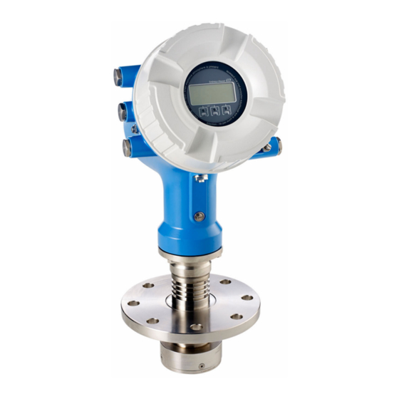
Product description Product description Product design A0027766 1 Design of Micropilot NMR84 Electronics housing Display and operating module (can be operated without opening the cover) Process connection (flange) Planar antenna Antenna extension (for antennas ≥ 200 mm (8 in)) -
Page 10: Incoming Acceptance And Product
• Do the nameplate data match the ordering information on the delivery note? • If required (see nameplate): Are the Safety Instructions (XA) enclosed? If one of these conditions is not satisfied, contact your Endress+Hauser Sales Center. Product identification The following options are available for identification of the measuring device: •... - Page 11 Certificate symbol Data concerning the Ex approval General certificate of approval Associated Safety Instructions (XA) Manufacturing date RoHS mark QR code for the Endress+Hauser Operations App 4.2.2 Manufacturer address Endress+Hauser SE+Co. KG Hauptstraße 1 79689 Maulburg, Germany Place of manufacture: See nameplate.
-
Page 12: Storage And Transport
Incoming acceptance and product identification Micropilot NMR84 Storage and transport 4.3.1 Storage conditions • Storage temperature: –50 to +80 °C (–58 to +176 °F) • Store the device in its original packaging. 4.3.2 Transport CAUTION Housing or antenna may be damaged or break away. -
Page 13: Installation
Micropilot NMR84 Installation Installation Installation conditions 5.1.1 Conditions for the stilling well • Metal (no enamel coating) • Constant diameter (no rectangular stilling wells) • Weld seam as smooth as possible • For best radar propagation behavior it is recommended to have holes instead of slots. If slots can not be avoided, they should be as thin and short as possible. -
Page 14: Post-Installation Check
Installation Micropilot NMR84 100 mm (4 in) 150 mm (6 in) 300 mm (12 in) 150 mm (6 in) 200 mm (8 in) 300 mm (12 in) 200 mm (8 in) 250 mm (10 in) 300 mm (12 in) 250 mm (10 in) -
Page 15: Electrical Connection
Micropilot NMR84 Electrical connection Electrical connection Terminal assignment POWER POWER G1 N AC 85...264 V G3 L A0026372 4 Terminal compartment (typical example) and ground terminals Terminal area A/B/C/D (slots for I/O modules) Module: Up to four I/O modules, depending on the order code •... - Page 16 Electrical connection Micropilot NMR84 A0018339 5 Terminal area: Protective ground 6.1.1 Power supply POWER POWER G1 N AC 85...264 V A0033413 not connected Green LED: indicates power supply The supply voltage is also indicated on the nameplate. Supply voltage...
- Page 17 Micropilot NMR84 Electrical connection 6.1.2 Remote display and operating module DKX001 81 82 83 84 F1 F2 F3 F4 POWER A0037025 6 Connection of the remote display and operating module DKX001 to the Tank Gauging device (NMR8x, NMS8x or NRF8x)
- Page 18 Electrical connection Micropilot NMR84 6.1.4 Slots for I/O modules The terminal compartment contains four slots (A, B, C and D) for I/O modules. Depending on the device version (ordering features 040, 050 and 060) these slots contain different I/O modules. The table below shows which module is located in which slot for a specific device version.
- Page 19 Micropilot NMR84 Electrical connection "Primary Output" (040) = "Modbus" (A1) NMx8x - xxxx XX XX XX A0023888 A/XP A/XP A/XP A/XP A/XP A/XP A/XP A/XP A/XP A/XP A/XP A/IS A/IS A/IS A/IS A/IS A/IS A/IS A/IS A/IS A/IS A/IS A/IS...
- Page 20 Electrical connection Micropilot NMR84 List of abbreviations used in table "Primary Output" (040) = "V1" (B1) • O - Ordering feature • T - Terminal area • 040 - Primary Output • 050 - Secondary IO Analog • 060 - Secondary IO Digital Ex d/XP •...
- Page 21 Micropilot NMR84 Electrical connection "Primary Output" (040) = "V1" (B1) NMx8x - xxxx XX XX XX A0023888 A/XP A/XP A/XP A/XP A/XP A/XP A/XP A/XP A/XP A/XP A/XP A/IS A/IS A/IS A/IS A/IS A/IS A/IS A/IS A/IS A/IS A/IS A/IS...
- Page 22 Electrical connection Micropilot NMR84 List of abbreviations used in table "Primary Output" (040) = "WM550" (C1) • O - Ordering feature • T - Terminal area • 040 - Primary Output • 050 - Secondary IO Analog • 060 - Secondary IO Digital Ex d/XP •...
- Page 23 Micropilot NMR84 Electrical connection "Primary Output" (040) = "WM550" (C1) NMx8x - xxxx XX XX XX A0023888 WM550 WM550 WM550 WM550 WM550 WM550 WM550 WM550 WM550 WM550 WM550 WM550 WM550 WM550 A/XP WM550 A/XP WM550 A/XP WM550 A/XP WM550 A/XP...
- Page 24 Electrical connection Micropilot NMR84 NMx8x - xxxx XX XX XX A0023888 WM550 A/IS A/IS WM550 A/IS A/IS WM550 WM550 A/IS A/XP WM550 A/IS A/XP WM550 A/IS A/XP WM550 A/IS A/XP WM550 Ordering feature Terminal area Primary Output Secondary IO Analog Secondary IO Digital Ex d/XP List of abbreviations used in table "Primary Output"...
- Page 25 Micropilot NMR84 Electrical connection "Primary Output" (040) = "4-20mA HART Ex d" (E1) NMx8x - xxxx XX XX XX A0023888 A/XP A/XP A/XP A/XP A/XP A/XP A/XP A/XP A/XP A/XP A/XP A/XP A/XP A/XP A/XP A/XP A/XP A/XP A/IS A/XP...
- Page 26 Electrical connection Micropilot NMR84 "Primary Output" (040) = "4-20mA HART Ex i" (H1) NMx8x - xxxx XX XX XX A0023888 A/IS A/IS A/IS A/IS A/IS A/IS A/IS A/IS A/XP A/IS A/XP A/IS A/XP A/IS A/XP A/IS A/XP A/IS A/IS A/IS...
- Page 27 Micropilot NMR84 Electrical connection 6.1.5 Terminals of the "Modbus" module, "V1" module or "WM550" module 1 2 3 4 D1-4 1 2 3 4 POWER A1-4 A0031200 7 Designation of the "Modbus", "V1" or "WM550" modules (examples); depending on the device version these modules may also be in slot B or C.
- Page 28 Electrical connection Micropilot NMR84 Terminals of the "V1" and "WM550" module Designation of the module in the operating menu: V1 X1-4 or WM550 X1-4; (X = A, B, C or D) • X1 • Terminal name: S • Description: Cable shielding connected via a capacitor to EARTH •...
- Page 29 Micropilot NMR84 Electrical connection Terminal: C4-8 Function: Analog input • RTD: → 33 • Designation in the operating menu: Analog IP C4-8 (→ 132) Endress+Hauser...
- Page 30 Electrical connection Micropilot NMR84 6.1.7 Connection of the "Analog I/O" module for passive usage • In the passive usage the supply voltage for the communication line must be supplied by an external source. • The wiring must be in accordance with the intended operating mode of the Analog I/O module;...
- Page 31 Micropilot NMR84 Electrical connection "Operating mode" = "HART master" POWER – A0027934 10 Passive usage of the Analog I/O module in the HART master mode Power supply Up to 6 external devices with HART signal output Endress+Hauser...
- Page 32 Electrical connection Micropilot NMR84 6.1.8 Connection of the "Analog I/O" module for active usage • In the active usage the supply voltage for the communication line is supplied by the device itself. There is no need of an external power supply.
- Page 33 Micropilot NMR84 Electrical connection "Operating mode" = "HART master" POWER A0027936 13 Active usage of the Analog I/O module in the HART master mode Up to 6 external devices with HART signal output The maximum current consumption for the connected HART devices is 24 mA (i.e.
- Page 34 Electrical connection Micropilot NMR84 6.1.10 Terminals of the "Digital I/O" module 1 2 3 4 5 6 7 C1-2 C3-4 1 2 3 4 POWER A1-2 A3-4 A0026424 14 Designation of the digital inputs or outputs (examples) • Each Digital IO Module provides two digital inputs or outputs.
-
Page 35: Connecting Requirements
Micropilot NMR84 Electrical connection Connecting requirements 6.2.1 Cable specification Terminals Wire cross section 0.2 to 2.5 mm (24 to 13 AWG) Use for terminals with function: Signal and power supply • Spring terminals (NMx8x-xx1...) • Screw terminals (NMx8x-xx2...) Wire cross section max. 2.5 mm... -
Page 36: Ensuring The Degree Of Protection
Electrical connection Micropilot NMR84 Ensuring the degree of protection To guarantee the specified degree of protection, carry out the following steps after the electrical connection: 1. Check that the housing seals are clean and fitted correctly. Dry, clean or replace the seals if necessary. -
Page 37: Operability
Micropilot NMR84 Operability Operability Overview of the operation options The device is operated via an operating menu → 38. This menu can be accessed by the following interfaces: • The display and operating module at the device or the remote display and operating module DKX001 (→... -
Page 38: Structure And Function Of The Operating Menu
Operability Micropilot NMR84 Structure and function of the operating menu Menu Submenu / Meaning parameter Operation Level Shows the measured and calculated level values. Temperature Shows the measured and calculated temperature values. Density Shows the measured and calculated density values. -
Page 39: Access To The Operating Menu Via The Local Or Remote Display And Operating Module
Micropilot NMR84 Operability Access to the operating menu via the local or remote display and operating module • Operating via the remote display and operating module DKX001 (→ 17) or the local display and operating module at the device are equivalent. - Page 40 Operability Micropilot NMR84 7.3.2 Standard view (measured value display) X X X X X X X 4841.00 A0028317 16 Typical appearance of the standard view (measured value display) Display module Device tag Status area Display area for measured values...
- Page 41 Micropilot NMR84 Operability Symbol 1 Symbol 2 Measured value P1 (bottom) A0028141 A0028151 P2 (middle) A0028142 A0028151 P3 (top) A0028146 A0028151 GP 1 value This is used for an external device. A0027992 A0028141 GP 2 value This is used for an external device.
- Page 42 Operability Micropilot NMR84 7.3.3 Navigation view 00215-1 /../Setup Tank level 5500.00 mm Mapping Advanced Setup A0045875 17 Navigation view Current submenu or wizard Quick access code Display area for navigation Navigation symbols Symbol Meaning Operation Is displayed: • in the main menu next to the selection Operation A0011975 •...
- Page 43 Micropilot NMR84 Operability Meaning of the keys in the navigation view Meaning Minus key Moves the selection bar upwards in a picklist. A0028324 Plus key Moves the selection bar downwards in a picklist. A0028325 Enter key • Pressing the key briefly opens the selected menu, submenu or parameter.
- Page 44 Operability Micropilot NMR84 7.3.5 Numeric editor A0028341 19 Numeric editor on the display module Display area of the entered value Input mask Symbol Meaning Selection of numbers from 0 to 9. … A0013998 Inserts decimal separator at the input position.
- Page 45 Micropilot NMR84 Operability 7.3.6 Text editor A0028342 20 Text editor on the display module Display area of the entered text Input mask Text editor symbols Symbol Meaning Selection of letters from A to Z ABC _ … A0013997 Toggle •...
- Page 46 Operability Micropilot NMR84 Meaning of the keys in the text editor Meaning Minus key In the input mask, moves the selection bar to the left (backwards). A0028324 Plus key In the input mask, moves the selection bar to the right (forwards).
- Page 47 Micropilot NMR84 Operability 7.3.8 Access code and user roles Meaning of the access code An access code can be defined in order to distinguish between the following user roles: User role Definition Maintenance • Knows the access code. • Has write access to all parameters (except service parameters).
- Page 48 Operability Micropilot NMR84 7.3.9 Write protection switch The operating menu can be locked by a hardware switch in the connection compartment. In this locking state W&M related parameters are read only. 6 mm 2.5 Nm (1.84 lbf ft) A0028363 The display module can be attached to the edge of the electronics compartment. This makes it easier to access the lock switch.
- Page 49 Micropilot NMR84 Operability A0028381 Indication of the locking state X X X X X X X 20.50 A0015870 22 Write protection symbol in the header of the display Write protection via locking switch is indicated as follows: • Locking status (→ 124) = Hardware locked •...
-
Page 50: Access To The Operating Menu Via The Service Interface And Fieldcare
FieldCare A0023737 23 Operation via service interface Service interface (CDI = Endress+Hauser Common Data Interface) Commubox FXA291 Computer with "FieldCare" operating tool and "CDI Communication FXA291" COM DTM The "Save/Restore" function After a device configuration has been saved to a computer and restored to the device... - Page 51 Micropilot NMR84 Operability 7.5.2 Establishing the connection between FieldCare and the device 1. Make sure the HART CommDTM NXA is installed and update the DTM catalogue if required. 2. Create a new project in FieldCare. A0028515 Add a new device: NXA HART Communication...
- Page 52 Operability Micropilot NMR84 A0028517 Select Create network from the context menu. The device is detected and the DTM is assigned. A0032933 The device can be configured. The "Save/Restore" function After a device configuration has been saved to a computer and restored to the device...
-
Page 53: System Integration
Micropilot NMR84 System integration System integration Overview of the Device Description files (DTM) To integrate the device via HART into FieldCare, a Device Description file (DTM) according to the following specification is required: Manufacturer ID 0x11 Device type (NMR8x) 0x112E... -
Page 54: Commissioning
Commissioning Micropilot NMR84 Commissioning Terms related to tank measurement A0029801 25 Terms related to radar tank measurement Gauge reference height Empty Datum plate Tank ullage Tank level Tank reference height Distance Dipping reference Initial settings 9.2.1 Setting the display language Setting the display language via the display module 1. - Page 55 Micropilot NMR84 Commissioning 2. Select the display language. This setting only affects the language on the display module. To set the language in the operating tool use the language setting functionality of FieldCare or DeviceCare, respectively. 9.2.2 Setting the real-time clock Setting the real-time clock via the display module 1.
- Page 56 Commissioning Micropilot NMR84 Go to the Set date parameter and select the Confirm time option. The real-time clock is set to the current date and time. Endress+Hauser...
-
Page 57: Configuring The Measuring Device
Micropilot NMR84 Commissioning Configuring the measuring device 9.3.1 Configuration of the level measurement The first parameters of the Setup menu are used to configure the measurement. A short description is given in the following sections. For a more detailed description refer to the parameter description in the appendix →... - Page 58 Commissioning Micropilot NMR84 Dip table The dip table is used to correct the level readings using independently taken hand dips. The dip table is used in particular to adapt the level gauge to the specific application conditions such as a mechanical offset and the tank or stilling well design.
-
Page 59: Configuring The Tank Gauging Application
Micropilot NMR84 Commissioning Configuring the tank gauging application Configuration of the inputs: Description HART inputs → 60 NMT532/539/81 connected via HART → 62 4-20mA inputs → 64 RTD input → 65 Digital inputs → 67... - Page 60 Commissioning Micropilot NMR84 9.4.1 Configuration of the HART inputs Connecting and addressing HART devices 1 2 3 4 5 6 7 8 C1-3 C4-8 1 2 3 4 5 6 7 8 POWER B1-3 B4-8 A0032955 26 Possible terminals for HART loops Analog I/O module in slot B (availability depending on device version →...
- Page 61 Micropilot NMR84 Commissioning Defining the type of measured value This setting can be skipped for a connected Prothermo NMT5xx and NMT8x as the type of measured value is automatically recognized by the Micropilot NMR8x in this case. • The measured values can only be used in the system if the unit of the assigned HART variable fits the type of measured value.
- Page 62 Commissioning Micropilot NMR84 9.4.2 Configuration of a connected Prothermo temperature transmitter If a Prothermo NMT532, NMT539 or NMT8x temperature transmitter is connected via HART, it can be configured as follows: 1. Navigate to: Expert → Input/output → HART devices → HART Device(s) → NMT device config;...
- Page 63 Micropilot NMR84 Commissioning A0047111 28 Prothermo NMT8x: Distance between the physical end of the probe and the zero level value Distance between the physical end of the probe and the zero level value in the tank (tank bottom or datum plate).
- Page 64 Commissioning Micropilot NMR84 9.4.3 Configuration of the 4-20mA inputs 1 2 3 4 5 6 7 8 C1-3 C4-8 1 2 3 4 5 6 7 8 POWER B1-3 B4-8 A0032464 29 Possible locations of the Analog I/O modules, which can be used as a 4-20mA input. The order code of the device determines which of these modules is actually present →...
- Page 65 Micropilot NMR84 Commissioning 9.4.4 Configuration of a connected RTD 1 2 3 4 5 6 7 8 1 2 3 4 5 6 7 8 C1-3 C4-8 1 2 3 4 5 6 7 8 1 2 3 4 5 6 7 8...
- Page 66 Commissioning Micropilot NMR84 A0042773 Datum plate Probe position (→ 136) Go to the Probe position parameter and enter the mounting position of the RTD (measured from the datum plate). This parameter, in conjunction with the measured level, determines whether the measured temperature refers to the product or to the gas phase.
- Page 67 Micropilot NMR84 Commissioning 9.4.5 Configuration of the digital inputs 1 2 3 4 5 6 7 C1-2 C3-4 1 2 3 4 POWER A1-2 A3-4 A0026424 33 Possible locations of the Digital I/O modules (examples); the order code defines the number and location of digial input modules →...
- Page 68 Commissioning Micropilot NMR84 This parameter determines how the state of the external switch is mapped to the internal states of the DIO module: State of the external switch Internal state of the DIO module Contact type = Normally open Contact type = Normally closed...
- Page 69 Micropilot NMR84 Commissioning 9.4.7 Tank calculation: Direct level measurement If no tank calculation is configured, level and temperature are measured directly. A0029255 Direct level measurement (without temperature) Direct level and temperature measurement Level transmitter To inventory management system Temperature transmitter ‣...
- Page 70 Commissioning Micropilot NMR84 9.4.8 Tank calculation: Hybrid tank measurement system (HTMS) HTMS uses level and pressure measurements to calculate the density of the medium. In non-atmospheric (i.e. pressurized) tanks it is recommended to use the HTMS P1+P3 mode. Two pressure sensors are required in this case. In atmospheric (i.e.
- Page 71 Micropilot NMR84 Commissioning 9.4.9 Tank calculation: Hydrostatic Tank Deformation (HyTD) Hydrostatic Tank Deformation can be used to compensate the vertical movement of the Gauge Reference Height (GRH) due to bulging of the tank shell caused by the hydrostatic pressure exerted by the liquid stored in the tank. The compensation is based on a linear approximation obtained from manual hand dips at several levels divided over the full range of the tank.
- Page 72 Commissioning Micropilot NMR84 9.4.10 Tank calculation: Thermal tank shell correction (CTSh) CTSh (correction for the thermal expansion of the tank shell) compensates for effects on the Gauge Reference Height (GRH) and on the expansion or contraction of the measuring wire due to temperature effects on the tank shell or stilling well. The temperature effects are separated into two parts, respectively affecting the ' d ry' and ' w etted' part of the tank shell or stilling well.
- Page 73 Micropilot NMR84 Commissioning 9.4.11 Configuration of the alarms (limit evaluation) A limit evaluation can be configured for up to 4 tank variables. The limit evaluation issues an alarm if the value exceeds an upper limit or falls below a lower limit, respectively. The limit values can be defined by the user.
- Page 74 Commissioning Micropilot NMR84 9.4.12 Configuration of the 4-20mA output 1 2 3 4 5 6 7 8 C1-3 C4-8 1 2 3 4 5 6 7 8 POWER B1-3 B4-8 A0032464 36 Possible locations of the Analog I/O modules, which can be used as a 4-20mA output. The order code of the device determines which of these modules is actually present →...
- Page 75 Micropilot NMR84 Commissioning 9.4.13 Configuration of the HART slave + 4-20mA output If Operating mode = HART slave +4..20mA output has been selected for an Analog I/O module, it serves as a HART slave which sends up to four HART variables to a HART master.
- Page 76 Commissioning Micropilot NMR84 After startup of the device, as long as the assigned tank variable is not yet available, the output current assumes the defined errror value. The PV mA selector parameter does not influence the output current at the terminals of the Analog I/O module.
- Page 77 Micropilot NMR84 Commissioning 9.4.15 Configuration of the V1 output 1 2 3 4 D1-4 1 2 3 4 POWER A1-4 A0031200 40 Possible locations of the V1 modules (examples); depending on the device version these modules may also be in slot B or C → 18.
- Page 78 Commissioning Micropilot NMR84 9.4.17 Configuration of the digital outputs 1 2 3 4 5 6 7 C1-2 C3-4 1 2 3 4 POWER A1-2 A3-4 A0026424 42 Possible locations of the Digital I/O modules (examples); the order code defines the number and location of Digital I/O modules →...
-
Page 79: Advanced Settings
Micropilot NMR84 Commissioning • State of the alarm Switching state of the digital output • Internal state of the digital input Contact type = Normally open Contact type = Normally closed Inactive Open Closed Active Closed Open • For SIL applications, Contact type is automatically set to Normally closed by the device when starting the SIL confirmation procedure. -
Page 80: Operation
Operation Micropilot NMR84 Operation 10.1 Reading off the device locking status Depending on the locking state of the device some operations may be locked. The current locking status is indicated at: Setup → Advanced setup → Locking status. The following... -
Page 81: Diagnostics And Troubleshooting
Micropilot NMR84 Diagnostics and troubleshooting Diagnostics and troubleshooting 11.1 General trouble shooting 11.1.1 General errors Error Possible cause Remedial action Device does not respond. Supply voltage not connected. Connect the correct voltage. The cables do not contact the Ensure electrical contact between the terminals properly. -
Page 82: Diagnostic Information On Local Display
Diagnostics and troubleshooting Micropilot NMR84 11.2 Diagnostic information on local display 11.2.1 Diagnostic message Faults detected by the self-monitoring system of the measuring device are displayed as a diagnostic message in alternation with the measured value display. Measured value display in alarm condition... - Page 83 Micropilot NMR84 Diagnostics and troubleshooting Diagnostics event and event text The fault can be identified using the diagnostics event. The event text helps you by providing information about the fault. In addition, the corresponding symbol is displayed before the diagnostics event.
- Page 84 Diagnostics and troubleshooting Micropilot NMR84 11.2.2 Calling up remedial measures X X X X X X X X X X X X X X 20.50 S801 Supply voltage Menu Diagnostic list Diagnostics 1 S801 Supply voltage Diagnostics 2 Diagnostics 3...
-
Page 85: Diagnostic Information In Fieldcare
Micropilot NMR84 Diagnostics and troubleshooting 11.3 Diagnostic information in FieldCare Any faults detected by the measuring device are displayed on the home page of the operating tool once the connection has been established. Xxxxxx/…/…/ Device name: Xxxxxxx Mass flow: kg/h 12.34... - Page 86 Diagnostics and troubleshooting Micropilot NMR84 11.3.2 Calling up remedy information Remedy information is provided for every diagnostic event to ensure that problems can be rectified quickly: • On the home page Remedy information is displayed in a separate field below the diagnostics information.
-
Page 87: Overview Of The Diagnostic Messages
Micropilot NMR84 Diagnostics and troubleshooting 11.4 Overview of the diagnostic messages Diagnostic Short text Remedy instructions Status Diagnostic number signal behavior [from the [from the factory] factory] Diagnostic of sensor Sensor incompatible error 1. Restart device Alarm 2. Contact service Detector error 1. - Page 88 Diagnostics and troubleshooting Micropilot NMR84 Diagnostic Short text Remedy instructions Status Diagnostic number signal behavior [from the [from the factory] factory] System recovery failure HW changed, system recovery Alarm failure. Return to factory Displacer distance invalid 1. Calibrate sensor Alarm 2.
- Page 89 Micropilot NMR84 Diagnostics and troubleshooting Diagnostic Short text Remedy instructions Status Diagnostic number signal behavior [from the [from the factory] factory] AIO 1 to 2 current output 1. Check process Warning warning 2. Check current output settings AIO 1 to 2 Input not HART...
- Page 90 Diagnostics and troubleshooting Micropilot NMR84 Diagnostic Short text Remedy instructions Status Diagnostic number signal behavior [from the [from the factory] factory] One time cmd source no Change input source Warning longer valid Alarm 1 to 4 source no Change input source...
- Page 91 Micropilot NMR84 Diagnostics and troubleshooting Diagnostic Short text Remedy instructions Status Diagnostic number signal behavior [from the [from the factory] factory] Calibration mandatory 1. Carry out weight calibration Alarm 2. Carry out reference calibration 3. Carry out drum calibration DIO B1-2 source no longer...
- Page 92 Diagnostics and troubleshooting Micropilot NMR84 Diagnostic Short text Remedy instructions Status Diagnostic number signal behavior [from the [from the factory] factory] Alarm 1 to 4 HighHigh 1. Check alarm source Warning 2. Check configuration settings Alarm 1 to 4 High 1.
-
Page 93: Diagnostic List
Micropilot NMR84 Diagnostics and troubleshooting 11.5 Diagnostic list In the Diagnostic list submenu, up to 5 currently pending diagnostic messages can be displayed. If more than 5 messages are pending, the messages with the highest priority are shown on the display. -
Page 94: Maintenance
12.2 Endress+Hauser services Endress+Hauser offers a wide variety of services for maintenance such as recalibration, maintenance service or device tests. Your Endress+Hauser Sales Center can provide detailed information on the services. -
Page 95: Repair
13.1.1 Repair concept The Endress+Hauser repair concept assumes that the devices have a modular design and that repairs can be done by the Endress+Hauser service or specially trained customers. Spare parts are contained in suitable kits. They contain the related replacement instructions. -
Page 96: Spare Parts
Instructions. 13.3 Endress+Hauser services Endress+Hauser offers a wide range of services. Your Endress+Hauser Sales Center can provide detailed information on the services. 13.4 Return The requirements for safe device return can vary depending on the device type and national legislation. -
Page 97: Accessories
Micropilot NMR84 Accessories Accessories 14.1 Device-specific accessories 14.1.1 Weather protection cover 361.6 (14.2) A0028019 45 Weather protection cover; dimensions: mm (in) Materials • Protection cover and mounting brackets Material 316L (1.4404) • Screws and washers Material • The weather protection cover can be ordered together with the device: Ordering feature 620 "Accessory Enclosed", option PA "Weather Protection Cover") -
Page 98: Communication-Specific Accessories
For intrinsically safe HART communication with FieldCare via the USB interface For details, see "Technical Information" TI00404F Commubox FXA291 Connects Endress+Hauser field devices with a CDI interface (= Endress+Hauser Common Data Interface) and the USB port of a computer or laptop Order number: 51516983 For details, see "Technical Information"... -
Page 99: System Components
Micropilot NMR84 Accessories 14.4 System components RIA15 Compact process display unit with very low voltage drop for universal use to display 4 to 20 mA/HART signals Technical Information TI01043K Tankvision Tank Scanner NXA820 / Tankvision Data Concentrator NXA821 / Tankvision Host Link NXA822... -
Page 100: Operating Menu
Operating menu Micropilot NMR84 Operating menu • : Navigation path for operating module at the device • : Navigation path for operating tool (e.g. FieldCare) • : Parameter can be locked via software locking 15.1 Overview of the operating menu •... - Page 101 Micropilot NMR84 Operating menu Vapor temperature → 112 ‣ → 112 NMT element values ‣ Element temperature → 112 Element temperature 1 to 24 → 112 ‣ Element position → 113 Element position 1 to 24 →...
- Page 102 Operating menu Micropilot NMR84 Tube diameter → 119 Empty → 119 → 119 Tank reference height Tank level → 109 Set level → 120 Confirm distance → 120 → 122 Present mapping Mapping end point →...
- Page 103 Micropilot NMR84 Operating menu Process value → 134 → 134 Process variable 0 % value → 134 100 % value → 135 Input value → 135 Minimum probe temperature → 135 Maximum probe temperature →...
- Page 104 Operating menu Micropilot NMR84 Error event type → 145 Process value → 145 → 145 Input value in mA Input value percent → 146 Damping factor → 146 Used for SIL/WHG → 146 → 147 Expected SIL/WHG chain ‣...
- Page 105 Micropilot NMR84 Operating menu ‣ V1 input selector → 160 ‣ → 162 WM550 input selector ‣ HART output → 164 ‣ Configuration → 164 ‣ Information → 172 ‣ Application → 174 ‣...
- Page 106 Operating menu Micropilot NMR84 ‣ Information → 220 Signal quality → 220 → 220 Absolute echo amplitude Relative echo amplitude → 221 Distance → 123 ‣ Echo tracking → 222 → 222 Evaluation mode History reset →...
- Page 107 Micropilot NMR84 Operating menu Temperature unit → 231 → 231 Density unit ‣ Date / time → 233 Date/time → 233 Set date → 233 Year → 233 Month → 234 → 234 Hour →...
- Page 108 Operating menu Micropilot NMR84 ‣ Diagnostic list → 242 Diagnostics 1 to 5 → 242 → 242 Timestamp 1 to 5 ‣ Device information → 243 Device tag → 243 Serial number → 243 →...
-
Page 109: Operation" Menu
Micropilot NMR84 Operating menu 15.2 "Operation" menu The Operation menu (→ 109) shows the most important measured values. Navigation Operation 15.2.1 "Level" submenu Navigation Operation → Level Tank level Navigation Operation → Level → Tank level... - Page 110 Operating menu Micropilot NMR84 Tank ullage % Navigation Operation → Level → Tank ullage % Description Shows the remaining empty space in percentage related to parameter tank reference height. Additional information Read access Operator Write access Upper interface level Navigation ...
- Page 111 Micropilot NMR84 Operating menu Measured level Navigation Operation → Level → Measured level Description Shows the measured level without any correction from the tank calculations. Additional information Read access Operator Write access Distance Navigation Operation → Level → Distance Description Distance from lower edge of device flange to product surface.
- Page 112 Operating menu Micropilot NMR84 Vapor temperature Navigation Operation → Temperature → Vapor temp. Description Shows the measured vapor temperature. Additional information Read access Operator Write access "NMT element values" submenu This submenu is only visible if a Prothermo NMT is connected.
- Page 113 Micropilot NMR84 Operating menu "Element position" submenu Navigation Operation → Temperature → NMT elem. values → Element position Element position 1 to 24 Navigation Operation → Temperature → NMT elem. values → Element position → Element pos. 1 to 24 Description Shows the position of the selected element in the NMT.
- Page 114 Operating menu Micropilot NMR84 Additional information Read access Operator Write access Maintenance Air density Navigation Operation → Density → Air density Description Defines the density of the air surrounding the tank. User entry 0.0 to 500.0 kg/m³ Factory setting 1.2 kg/m³...
- Page 115 Micropilot NMR84 Operating menu Additional information Read access Maintenance Write access 15.2.4 "Pressure" submenu Navigation Operation → Pressure P1 (bottom) Navigation Operation → Pressure → P1 (bottom) Description Shows the pressure at the tank bottom. Additional information Read access...
- Page 116 Operating menu Micropilot NMR84 15.2.5 "GP values" submenu Navigation Operation → GP values GP 1 to 4 name Navigation Operation → GP values → GP 1 name Description Defines the label associated with the respective GP value.
- Page 117 Micropilot NMR84 Operating menu Additional information Read access Operator Write access GP Value 4 Navigation Operation → GP values → GP Value 4 Description Displays the value that will be used as general purpose value. Additional information Read access...
-
Page 118: Setup" Menu
Operating menu Micropilot NMR84 15.3 "Setup" menu Navigation Setup Device tag Navigation Setup → Device tag Description Enter a unique name for the measuring point to identify the device quickly within the plant. User entry Character string comprising numbers, letters and special characters (#32) - Page 119 Micropilot NMR84 Operating menu Tube diameter Navigation Setup → Tube diameter Description Enter diameter of stilling well. User entry Positive floating-point number Factory setting 150 mm Additional information Read access Operator Write access Maintenance Empty Navigation Setup → Empty Description Distance from reference point to zero position (tank bottom or datum plate).
- Page 120 Operating menu Micropilot NMR84 Additional information Read access Operator Write access Maintenance Tank level Navigation Setup → Tank level Description Shows the distance from the zero position (tank bottom or datum plate) to the product surface. Additional information Read access...
- Page 121 Micropilot NMR84 Operating menu Selection • Distance ok • Distance unknown • Distance too small • Distance too big • Tank empty • Manual map • Factory map Factory setting Distance unknown Additional information Read access Operator Write access Maintenance Meaning of the options •...
- Page 122 Operating menu Micropilot NMR84 Present mapping Navigation Setup → Present mapping Description Present end of mapping. Additional information Read access Operator Write access Mapping end point Navigation Setup → Map. end point Prerequisite Confirm distance (→ 120) = Manual map Description Defines up to which distance the new mapping has to be recorded.
- Page 123 Micropilot NMR84 Operating menu Meaning of the options • No The map is not recorded. • Record map The map is recorded. After the recording is completed, the new measured distance and the new mapping range appear on the display. When operating via the local display, these values must be confirmed by pressing .
- Page 124 Operating menu Micropilot NMR84 15.3.1 "Advanced setup" submenu Navigation Setup → Advanced setup Locking status Navigation Setup → Advanced setup → Locking status Description Indicates the type of locking. ' H ardware locked' (HW) The device is locked by the ' W P' switch on the main electronics module. To unlock, set the switch into the OFF position.
- Page 125 Micropilot NMR84 Operating menu "Input/output" submenu Navigation Setup → Advanced setup → Input/output "HART devices" submenu Navigation Setup → Advanced setup → Input/output → HART devices Number of devices Navigation Setup → Advanced setup → Input/output → HART devices → Number devices Description Shows the number of devices on the HART bus.
- Page 126 Operating menu Micropilot NMR84 "HART Device(s)" submenu There is a HART Device(s) submenu for each HART slave device found on the HART loop. Navigation Setup → Advanced setup → Input/output → HART devices → HART Device(s) Device name Navigation ...
- Page 127 Micropilot NMR84 Operating menu Operating mode Navigation Setup → Advanced setup → Input/output → HART devices → HART Device(s) → Operating mode Prerequisite Not available if the HART device is a Prothermo NMT. Description Selection of the operation mode PV only or PV,SV,TV,QV. Devines which values are polled from the connected HART Device.
- Page 128 Operating menu Micropilot NMR84 #blank# (HART SV - designation dependent on device) Navigation Setup → Advanced setup → Input/output → HART devices → HART Device(s) → #blank# Prerequisite For HART devices other than NMT: Operating mode (→ 127) = PV,SV,TV & QV Description Shows the second HART variable (SV).
- Page 129 Micropilot NMR84 Operating menu Description Defines which HART variable is the pressure. Selection • No value • Primary variable (PV) • Secondary variable (SV) • Tertiary variable (TV) • Quaternary variable (QV) Factory setting No value Additional information Read access...
- Page 130 Operating menu Micropilot NMR84 Factory setting No value Additional information Read access Operator Write access Maintenance Output vapor temperature Navigation Setup → Advanced setup → Input/output → HART devices → HART Device(s) → Output vapor tmp Prerequisite Not available for Micropilot S FMR5xx, Prothermo NMT53x and Prothermo NMT8x. In these cases the measured variables are allocated automatically.
- Page 131 Micropilot NMR84 Operating menu "Forget device" wizard Read access Maintenance This submenu is only visible if Number of devices (→ 125) ≥ 1. Navigation Setup → Advanced setup → Input/output → HART devices → Forget device Forget device ...
- Page 132 Operating menu Micropilot NMR84 "Analog IP" submenu There is a Analog IP submenu for each Analog I/O module of the device. This submenu refers to terminals 4 to 8 of this module (the analog input). They are primarily used to connect an RTD. For terminals 1 to 3 (analog input or output) refer to →...
- Page 133 Micropilot NMR84 Operating menu Selection • Cu50 (w=1.428, GOST) • Cu53 (w=1.426, GOST) • Cu90; 0°C (w=1.4274, GOST) • Cu100; 25°C (w=1.4274, GOST) • Cu100; 0°C(w=1.4274, GOST) • Pt46 (w=1.391, GOST) • Pt50 (w=1.391, GOST) • Pt100(385) (a=0.00385, IEC751) • Pt100(389) (a=0.00389, Canadian) •...
- Page 134 Operating menu Micropilot NMR84 Selection • 4 wire RTD connection • 2 wire RTD connection • 3 wire RTD connection Factory setting 4 wire RTD connection Additional information Read access Operator Write access Maintenance Process value Navigation Setup → Advanced setup → Input/output → Analog IP → Process value Prerequisite Operating mode (→...
- Page 135 Micropilot NMR84 Operating menu Description Defines the value represented by a current of 4mA. User entry Signed floating-point number Factory setting 0 mm Additional information Read access Operator Write access Maintenance 100 % value Navigation Setup → Advanced setup → Input/output → Analog IP → 100 % value Prerequisite Operating mode (→...
- Page 136 Operating menu Micropilot NMR84 User entry –213 to 927 °C Factory setting –100 °C Additional information Read access Operator Write access Maintenance Maximum probe temperature Navigation Setup → Advanced setup → Input/output → Analog IP → Max. probe temp Prerequisite Operating mode (→...
- Page 137 Micropilot NMR84 Operating menu Damping factor Navigation Setup → Advanced setup → Input/output → Analog IP → Damping factor Prerequisite Operating mode (→ 132) ≠ Disabled Description Defines the damping constant (in seconds). User entry 0 to 999.9 s...
- Page 138 Operating menu Micropilot NMR84 "Analog I/O" submenu There is a Analog I/O submenu for each Analog I/O module of the device. This submenu refers to terminals 1 to 3 of this module (an analog input or output). For terminals 4 to 8 (always an analog input) refer to → 132.
- Page 139 Micropilot NMR84 Operating menu Operating mode (→ 138) Direction of signal Type of signal 4..20mA output Output to higher-level unit Analog (4...20mA) HART slave +4..20mA output Output to higher-level unit • Analog (4...20mA) • HART Depending on the terminals used, the Analog I/O module is used in the passive or active mode.
- Page 140 Operating menu Micropilot NMR84 Option Current range Minimum Lower alarm Upper alarm Maximum for process value signal level signal level value variable 4...20 mA US 3.9 to 20.8 mA 3.5 mA < 3.6 mA > 21.95 mA 22.0 mA (3.9...20.8 mA) Fixed current Constant current, defined in the Fixed current parameter (→...
- Page 141 Micropilot NMR84 Operating menu • Air temperature • Observed density value • Average profile density • Upper density • Middle density • Lower density • P1 (bottom) • P2 (middle) • P3 (top) • GP 1 ... 4 value • AIO B1-3 value •...
- Page 142 Operating menu Micropilot NMR84 Error value Navigation Setup → Advanced setup → Input/output → Analog I/O → Error value Prerequisite Failure mode (→ 141) = Defined value Description Defines the output value in case of an error.
- Page 143 Micropilot NMR84 Operating menu 100 % value Navigation Setup → Advanced setup → Input/output → Analog I/O → 100 % value Prerequisite • Operating mode (→ 138) = 4..20mA output or HART slave +4..20mA output • Current span (→ 139) ≠ Fixed current Description Value corresponding to an output current of 100% (20mA).
- Page 144 Operating menu Micropilot NMR84 Process variable Navigation Setup → Advanced setup → Input/output → Analog I/O → Process variable Prerequisite Operating mode (→ 138) = 4..20mA input or HART master+4..20mA input Description Defines the type of measuring variable.
- Page 145 Micropilot NMR84 Operating menu Additional information Read access Operator Write access Maintenance Error event type Navigation Setup → Advanced setup → Input/output → Analog I/O → Error event type Prerequisite Operating mode (→ 138) ≠ Disabled or HART master...
- Page 146 Operating menu Micropilot NMR84 Input value percent Navigation Setup → Advanced setup → Input/output → Analog I/O → Input value [%] Prerequisite Operating mode (→ 138) = 4..20mA input or HART master+4..20mA input Description Shows the input value as a percentage of the complete 4...20mA current range.
- Page 147 Micropilot NMR84 Operating menu Expected SIL/WHG chain Navigation Setup → Advanced setup → Input/output → Analog I/O → SIL/WHG chain Prerequisite • Operating mode (→ 138) = 4..20mA output or HART slave +4..20mA output • The device has a SIL approval.
- Page 148 Operating menu Micropilot NMR84 "Digital Xx-x" submenu • In the operating menu, each digital input or output is designated by the respective slot of the terminal compartment and two terminals within this slot. A1-2, for example, denotes terminals 1 and 2 of slot A. The same is valid for slots B, C and D if they contain a Digital IO module.
- Page 149 Micropilot NMR84 Operating menu Additional information A0033028 49 Operating modes of the Digital I/O module Input passive Input active Output passive Digital input source Navigation Setup → Advanced setup → Input/output → Digital Xx-x → Digital source Prerequisite Operating mode (→...
- Page 150 Operating menu Micropilot NMR84 Input value Navigation Setup → Advanced setup → Input/output → Digital Xx-x → Input value Prerequisite Operating mode (→ 148) = "Input passive" option or "Input active" option Description Shows the digital input value.
- Page 151 Micropilot NMR84 Operating menu A0028602 50 The two relays of a digital output 1/2 The relays 3/4 The terminals of the digital output The switching state of these relays is defined by the Output simulation parameter as follows: Output simulation...
- Page 152 Operating menu Micropilot NMR84 Additional information Read access Operator Write access Used for SIL/WHG Navigation Setup → Advanced setup → Input/output → Digital Xx-x → Used for SIL/WHG Prerequisite • Operating mode (→ 148) = Output passive •...
- Page 153 Micropilot NMR84 Operating menu "Communication" submenu This menu contains a submenu for each digital communication interface of the device. The communication interfaces are designated by "X1-4" where "X" specifies the slot in the terminal compartment and "1-4" the terminals within this slot.
- Page 154 Operating menu Micropilot NMR84 "Configuration" submenu This submenu is only present for devices with a MODBUS communication interface. Navigation Setup → Advanced setup → Communication → Modbus X1-4 → Configuration Baudrate Navigation Setup → Advanced setup → Communication → Modbus X1-4 → Configuration →...
- Page 155 Micropilot NMR84 Operating menu Modbus address Navigation Setup → Advanced setup → Communication → Modbus X1-4 → Configuration → Device ID Prerequisite Communication interface protocol (→ 153) = MODBUS Description Defines the Modbus address of the device.
- Page 156 Operating menu Micropilot NMR84 Factory setting Additional information Read access Operator Write access Maintenance Endress+Hauser...
- Page 157 Micropilot NMR84 Operating menu "Configuration" submenu This submenu is only present for devices with a V1 communication interface. Navigation Setup → Advanced setup → Communication → V1 X1-4 → Configuration Communication interface protocol variant Navigation Setup → Advanced setup → Communication → V1 X1-4 → Configuration → Protocol...
- Page 158 Operating menu Micropilot NMR84 V1 address Navigation Setup → Advanced setup → Communication → V1 X1-4 → Configuration → V1 address Prerequisite Communication interface protocol variant (→ 157) Description Identifier of the previous device for V1 communication.
- Page 159 Micropilot NMR84 Operating menu Number Corresponding level 500 001 –0.1 mm 999 999 –49 999.9 mm Line impedance Navigation Setup → Advanced setup → Communication → V1 X1-4 → Configuration → Line impedance Prerequisite Communication interface protocol (→ 153) = V1 Description Adjusts the impedance of the communication line.
- Page 160 Operating menu Micropilot NMR84 "V1 input selector" submenu This submenu is only present for devices with a V1 communication interface. Navigation Setup → Advanced setup → Communication → V1 X1-4 → V1 input select. Alarm 1 input source ...
- Page 161 Micropilot NMR84 Operating menu Value percent selector Navigation Setup → Advanced setup → Communication → V1 X1-4 → V1 input select. → Value % select Description Selects which value shall be transmitted as a 0..100% value in the V1 Z0/Z1 message.
- Page 162 Operating menu Micropilot NMR84 WM550 address Navigation Setup → Advanced setup → Communication → WM550 X1-4 → Configuration → WM550 address Description Describes the WM550 address of the device. User entry 0 to 63 Factory setting Software ID ...
- Page 163 Micropilot NMR84 Operating menu • Alarm 1...4 High or HighHigh • Alarm 1...4 High • Alarm 1...4 Low • Alarm 1...4 Low or LowLow • Alarm 1...4 LowLow • Digital Xx-x Factory setting None Additional information Read access Operator Write access...
- Page 164 Operating menu Micropilot NMR84 "HART output" submenu Navigation Setup → Advanced setup → Communication → HART output "Configuration" submenu Navigation Setup → Advanced setup → Communication → HART output → Configuration System polling address Navigation Setup → Advanced setup → Communication → HART output → Configuration →...
- Page 165 Micropilot NMR84 Operating menu Selection • AIO B1-3 • AIO C1-3 • Custom Factory setting Custom Additional information Read access Maintenance Write access Maintenance Assign PV Navigation Setup → Advanced setup → Communication → HART output → Configuration →...
- Page 166 Operating menu Micropilot NMR84 Additional information Read access Operator Write access Maintenance The Measured level option doesn' t contain a unit. If a unit is needed, select the Tank level option. 0 % value Navigation Setup → Advanced setup → Communication → HART output → Configuration → 0 %...
- Page 167 Micropilot NMR84 Operating menu Description Assigns a current to the primary HART variable (PV). Selection • None • AIO B1-3 value mA • AIO C1-3 value mA Factory setting None Additional information Read access Operator Write access Maintenance Primary variable (PV) Navigation ...
- Page 168 Operating menu Micropilot NMR84 • Measured level • Distance • Displacer position • Water level • Upper interface level • Lower interface level • Bottom level • Tank reference height • Liquid temperature • Vapor temperature • Air temperature • Observed density value •...
- Page 169 Micropilot NMR84 Operating menu Assign TV Navigation Setup → Advanced setup → Communication → HART output → Configuration → Assign TV Description Assign a measured variable to the tertiary dynamic variable (TV). Selection • None • Tank level •...
- Page 170 Operating menu Micropilot NMR84 Additional information Read access Operator Write access Assign QV Navigation Setup → Advanced setup → Communication → HART output → Configuration → Assign QV Description Assign a measured variable to the quaternary dynamic variable (QV).
- Page 171 Micropilot NMR84 Operating menu Quaternary variable (QV) Navigation Setup → Advanced setup → Communication → HART output → Configuration → Quaterna.var(QV) Prerequisite Assign QV (→ 170) ≠ None Description Shows the value of the fourth HART variable (QV).
- Page 172 Operating menu Micropilot NMR84 "Information" submenu Navigation Setup → Advanced setup → Communication → HART output → Information HART short tag Navigation Setup → Advanced setup → Communication → HART output → Information → HART short tag Description Defines the short tag for the measuring point.
- Page 173 Micropilot NMR84 Operating menu Factory setting NMR8x Additional information Read access Operator Write access Maintenance HART message Navigation Setup → Advanced setup → Communication → HART output → Information → HART message Description Use this function to define a HART message which is sent via the HART protocol when requested by the master.
- Page 174 Operating menu Micropilot NMR84 "Application" submenu Navigation Setup → Advanced setup → Application "Tank configuration" submenu Navigation Setup → Advanced setup → Application → Tank config "Level" submenu Navigation Setup → Advanced setup → Application → Tank config → Level Empty ...
- Page 175 Micropilot NMR84 Operating menu Additional information Read access Operator Write access Maintenance Tank level Navigation Setup → Advanced setup → Application → Tank config → Level → Tank level Description Shows the distance from the zero position (tank bottom or datum plate) to the product surface.
- Page 176 Operating menu Micropilot NMR84 • AIO B1-3 value • AIO C1-3 value • AIP B4-8 value • AIP C4-8 value Factory setting Manual value Additional information Read access Operator Write access Maintenance Manual water level Navigation Setup → Advanced setup → Application → Tank config → Level → Man. water level Prerequisite Water level source (→...
- Page 177 Micropilot NMR84 Operating menu Additional information Read access Operator Write access Maintenance Endress+Hauser...
- Page 178 Operating menu Micropilot NMR84 "Temperature" submenu Read access Maintenance Navigation Setup → Advanced setup → Application → Tank config → Temperature Liquid temp source Navigation Setup → Advanced setup → Application → Tank config → Temperature → Liq temp...
- Page 179 Micropilot NMR84 Operating menu Liquid temperature Navigation Setup → Advanced setup → Application → Tank config → Temperature → Liquid temp. Description Shows the average or spot temperature of the measured liquid. Additional information Read access Operator Write access Air temperature source ...
- Page 180 Operating menu Micropilot NMR84 Air temperature Navigation Setup → Advanced setup → Application → Tank config → Temperature → Air temp. Description Shows the air temperature. Additional information Read access Operator Write access Vapor temp source Navigation Setup → Advanced setup → Application → Tank config → Temperature → Vapor...
- Page 181 Micropilot NMR84 Operating menu Vapor temperature Navigation Setup → Advanced setup → Application → Tank config → Temperature → Vapor temp. Description Shows the measured vapor temperature. Additional information Read access Operator Write access Endress+Hauser...
- Page 182 Operating menu Micropilot NMR84 "Density" submenu Navigation Setup → Advanced setup → Application → Tank config → Density Observed density source Navigation Setup → Advanced setup → Application → Tank config → Density → Density source Description Determines how the density is obtained.
- Page 183 Micropilot NMR84 Operating menu Additional information Read access Operator Write access Maintenance Vapor density Navigation Setup → Advanced setup → Application → Tank config → Density → Vapor density Description Defines the density of the gas phase in the tank.
- Page 184 Operating menu Micropilot NMR84 "Pressure" submenu Navigation Setup → Advanced setup → Application → Tank config → Pressure P1 (bottom) source Navigation Setup → Advanced setup → Application → Tank config → Pressure → P1 (bot) source Description Defines the source of the bottom pressure (P1).
- Page 185 Micropilot NMR84 Operating menu Additional information Read access Operator Write access Maintenance P1 position Navigation Setup → Advanced setup → Application → Tank config → Pressure → P1 position Description Defines the position of the bottom pressure transmitter (P1), measured from zero position (tank bottom or datum plate).
- Page 186 Operating menu Micropilot NMR84 Additional information Read access Operator Write access Maintenance P3 (top) source Navigation Setup → Advanced setup → Application → Tank config → Pressure → P3 (top) source Description Defines the source of the top pressure (P3).
- Page 187 Micropilot NMR84 Operating menu Additional information Read access Operator Write access Maintenance P3 position Navigation Setup → Advanced setup → Application → Tank config → Pressure → P3 position Description Defines the position of the top pressure transmitter (P3), measured from zero position (tank bottom or datum plate).
- Page 188 Operating menu Micropilot NMR84 Additional information Read access Operator Write access Maintenance Ambient pressure Navigation Setup → Advanced setup → Application → Tank config → Pressure → Ambient pressure Description Defines the manual value of the ambient pressure.
- Page 189 Micropilot NMR84 Operating menu "Tank calculation" submenu Navigation Setup → Advanced setup → Application → Tank calculation "HyTD" submenu Overview Hydrostatic Tank Deformation can be used to compensate the vertical movement of the Gauge Reference Height (GRH) due to bulging of the tank shell caused by the hydrostatic pressure exerted by the liquid stored in the tank.
- Page 190 Operating menu Micropilot NMR84 Linear approximation of the HyTD correction The real amount of deformation varies non-linearly with the level due to the construction of the tank. However, as the correction values are typically small compared to the measured level, a simple straight line method can be used with good results.
- Page 191 Micropilot NMR84 Operating menu Description of parameters Navigation Setup → Advanced setup → Application → Tank calculation → HyTD HyTD correction value Navigation Setup → Advanced setup → Application → Tank calculation → HyTD → HyTD corr. value Description Shows the correction value from the Hydrostatic Tank Deformation.
- Page 192 Operating menu Micropilot NMR84 Deformation factor Navigation Setup → Advanced setup → Application → Tank calculation → HyTD → Deform factor Description Defines the deformation factor for the HyTD (change of device position per change of level). User entry –1.0 to 1.0 %...
- Page 193 Micropilot NMR84 Operating menu "CTSh" submenu Overview CTSh (correction for the thermal expansion of the tank shell) compensates for effects on the Gauge Reference Height (GRH) and on the expansion or contraction of the measuring wire due to temperature effects on the tank shell or stilling well. The temperature effects are separated into two parts, respectively affecting the ' d ry' and ' w etted' part of the tank shell or stilling well.
- Page 194 Operating menu Micropilot NMR84 CTSh: Calculation of the wall temperature A0028712 54 Parameters for the CTSh calculation Gauge Reference Height (GRH) Temperature of the wetted part of the tank shell Temperature of the dry part of the tank shell...
- Page 195 Micropilot NMR84 Operating menu A0030382 Covered tank (→ 196) = Covered; Stilling well (→ 197) = Yes Covered tank (→ 196) = Covered; Stilling well (→ 197) = No Covered tank (→ 196) = Open top; Stilling well (→ 197) = Yes Covered tank (→...
- Page 196 Operating menu Micropilot NMR84 Description of parameters Navigation Setup → Advanced setup → Application → Tank calculation → CTSh CTSh correction value Navigation Setup → Advanced setup → Application → Tank calculation → CTSh → CTSh corr value Description Shows the CTSh correction value.
- Page 197 Micropilot NMR84 Operating menu Additional information Read access Operator Write access Maintenance The Covered option is only valid for fixed tank roofs. For a floating roof select Open top. Stilling well Navigation Setup → Advanced setup → Application → Tank calculation → CTSh → Stilling well Description Determines whether the device is mounted on a stilling well.
- Page 198 Operating menu Micropilot NMR84 Additional information Read access Operator Write access Maintenance Wire expansion coefficient Navigation Setup → Advanced setup → Application → Tank calculation → CTSh → Wire exp coeff Description Defines the expansion coefficient of the wire material of the drum. Value is programmed in factory.
- Page 199 Micropilot NMR84 Operating menu "HTMS" submenu Overview The Hybrid Tank Measurement System (HTMS) is a method to calculate the density of a product in a tank based on both a (top mounted) level and at least one (bottom mounted) pressure measurement. An additional pressure sensor can be installed at the top of the tank to provide information about the vapor pressure and to make the density calculation more accurate.
- Page 200 Operating menu Micropilot NMR84 HTMS modes Two HTMS modes can be selected in the HTMS mode parameter (→ 201). The mode determines whether one or two pressure values are used. Depending on the selected mode a number of additional parameters are required for the calculation of the product density.
- Page 201 Micropilot NMR84 Operating menu Lmin A0029148 56 HTMS hysteresis Value calculated Value held/manual Minimum level (→ 202) Hysteresis (→ 203) Description of parameters Navigation Setup → Advanced setup → Application → Tank calculation → HTMS HTMS mode ...
- Page 202 Operating menu Micropilot NMR84 User entry 0 to 3 000 kg/m³ Factory setting 800 kg/m³ Additional information Read access Maintenance Write access Maintenance Density value Navigation Setup → Advanced setup → Application → Tank calculation → HTMS → Density value Description Shows the calculated product density.
- Page 203 Micropilot NMR84 Operating menu Additional information Read access Operator Write access Maintenance Safety distance Navigation Setup → Advanced setup → Application → Tank calculation → HTMS → Safety distance Description Defines the minimum level which must be present above the bottom pressure sensor before its signal is used for the calculation.
- Page 204 Operating menu Micropilot NMR84 Additional information Read access Operator Write access Maintenance Endress+Hauser...
- Page 205 Micropilot NMR84 Operating menu "Dip-table" submenu Dip table The dip table is used to correct the level readings using independently taken hand dips. The dip table is used in particular to adapt the level gauge to the specific application conditions such as a mechanical offset and the tank or stilling well design. Depending on national regulations, national inspectors will dip the tank at one to three levels during a calibration run and check the level readings.
- Page 206 Operating menu Micropilot NMR84 The table editor on the local display 1. Navigate to Setup → Advanced setup → Application → Tank calculation → Dip-table → Table mode and select the Disable option. 2. Navigate to Setup → Advanced setup → Application → Calculation → Dip-table → Edit table ...
- Page 207 Micropilot NMR84 Operating menu The table editor in FieldCare In the FieldCare table editor the dip table can only be entered manually. Even if the semiautomatic method has been selected in the Table settings parameter (→ 208), the complete table will be written from the editor to the device in the manual mode.
- Page 208 Operating menu Micropilot NMR84 Description of parameters Navigation Setup → Advanced setup → Application → Tank calculation → Dip-table Table settings Navigation Setup → Advanced setup → Application → Tank calculation → Dip-table → Table settings Description Defines the dip-table operation to be performed.
- Page 209 Micropilot NMR84 Operating menu Additional information Read access Operator Write access Maintenance "Alarm" submenu Navigation Setup → Advanced setup → Application → Alarm "Alarm" submenu Navigation Setup → Advanced setup → Application → Alarm → Alarm ‣ Alarm Alarm mode →...
- Page 210 Operating menu Micropilot NMR84 Alarm hysteresis → 217 Damping factor → 217 Alarm mode Navigation Setup → Advanced setup → Application → Alarm → Alarm → Alarm mode Description Defines the alarm mode of the selected alarm.
- Page 211 Micropilot NMR84 Operating menu A0029539 58 Principle of the limit evaluation Alarm mode (→ 210) = On Alarm mode (→ 210) = Latching HH alarm value (→ 213) H alarm value (→ 213) L alarm value (→ 214) LL alarm value (→...
- Page 212 Operating menu Micropilot NMR84 Alarm value source Navigation Setup → Advanced setup → Application → Alarm → Alarm → Alarm source Prerequisite Alarm mode (→ 210) ≠ Off Description Determines the process variable to be monitored. Selection •...
- Page 213 Micropilot NMR84 Operating menu Alarm value Navigation Setup → Advanced setup → Application → Alarm → Alarm → Alarm value Prerequisite Alarm mode (→ 210) ≠ Off Description Shows the current value of the process variable being monitored.
- Page 214 Operating menu Micropilot NMR84 L alarm value Navigation Setup → Advanced setup → Application → Alarm → Alarm → L alarm value Prerequisite Alarm mode (→ 210) ≠ Off Description Defines the low limit value. User entry...
- Page 215 Micropilot NMR84 Operating menu H alarm Navigation Setup → Advanced setup → Application → Alarm → Alarm → H alarm Prerequisite Alarm mode (→ 210) ≠ Off Description Shows whether an H alarm is currently active. Additional information...
- Page 216 Operating menu Micropilot NMR84 Additional information Read access Operator Write access LL+L alarm Navigation Setup → Advanced setup → Application → Alarm → Alarm → LL+L alarm Prerequisite Alarm mode (→ 210) ≠ Off Description Shows whether an LL or L alarm is currently active.
- Page 217 Micropilot NMR84 Operating menu Additional information Read access Operator Write access Maintenance Alarm hysteresis Navigation Setup → Advanced setup → Application → Alarm → Alarm → Alarm hysteresis Prerequisite Alarm mode (→ 210) ≠ Off Description Defines the hysteresis for the limit values. The hystersis prevents constant changes of the alarm state if the level is near one of the limit values.
- Page 218 Operating menu Micropilot NMR84 "Safety settings" submenu Navigation Setup → Advanced setup → Safety settings Output echo lost Navigation Setup → Advanced setup → Safety settings → Output echo lost Description Defines the output behavior in case of a lost echo.
- Page 219 Micropilot NMR84 Operating menu Additional information Read access Operator Write access Maintenance Endress+Hauser...
- Page 220 Operating menu Micropilot NMR84 "Sensor config" submenu Navigation Setup → Advanced setup → Sensor config Tube diameter Navigation Setup → Advanced setup → Sensor config → Tube diameter Description Enter diameter of stilling well. User entry Positive floating-point number...
- Page 221 Micropilot NMR84 Operating menu Relative echo amplitude Navigation Setup → Advanced setup → Sensor config → Information → Relat.echo ampl. Description Shows the relative amplitude (i.e. the distance to the evaluation curve) of the evaluated level signal. Additional information...
- Page 222 Operating menu Micropilot NMR84 "Echo tracking" submenu Navigation Setup → Advanced setup → Sensor config → Echo tracking Evaluation mode Navigation Setup → Advanced setup → Sensor config → Echo tracking → Evaluation mode Description Defines the evaluation mode for the echo tracking.
- Page 223 Micropilot NMR84 Operating menu "Display" submenu This menu is only visible if the device has a local display. Navigation Setup → Advanced setup → Display Language Navigation Setup → Advanced setup → Display → Language Prerequisite The device has a local display.
- Page 224 Operating menu Micropilot NMR84  93.5 %  159.0 A0019964 60 "Format display" = "1 bargraph + 1 value"  93.5  159.0 A0019965 61 "Format display" = "2 values"  159.0 mm  23.5 V  93.5 A0019966 ...
- Page 225 Micropilot NMR84 Operating menu Description Select the measured value that is shown on the local display. Selection • None • Tank level • Measured level • Level linearized • Tank level % • Water level • Liquid temperature • Vapor temperature •...
- Page 226 Operating menu Micropilot NMR84 Selection • x • x.x • x.xx • x.xxx • x.xxxx Factory setting Additional information The setting does not affect the measuring or computational accuracy of the device. Read access Operator Write access Maintenance Separator ...
- Page 227 Micropilot NMR84 Operating menu Header Navigation Setup → Advanced setup → Display → Header Prerequisite The device has a local display. Description Select header contents on local display. Selection • Device tag • Free text Factory setting Device tag...
- Page 228 Operating menu Micropilot NMR84 Additional information This parameter is only relevant if the number of selected measuring values exceeds the number of values the selected display format can display simultaneously. Read access Operator Write access Operator Display damping Navigation ...
- Page 229 Micropilot NMR84 Operating menu User entry 20 to 80 % Factory setting 30 % Additional information Read access Operator Write access Operator Endress+Hauser...
- Page 230 Operating menu Micropilot NMR84 "System units" submenu Navigation Setup → Advanced setup → System units Units preset Navigation Setup → Advanced setup → System units → Units preset Description Defines a set of units for length, pressure and temperature.
- Page 231 Micropilot NMR84 Operating menu Pressure unit Navigation Setup → Advanced setup → System units → Pressure unit Description Select process pressure unit. Selection SI units US units Other units • bar • inH2O • Pa • inH2O (68°F) •...
- Page 232 Operating menu Micropilot NMR84 Additional information Read access Operator Write access Maintenance (if Units preset (→ 118) = Customer value) Endress+Hauser...
- Page 233 Micropilot NMR84 Operating menu "Date / time" submenu Navigation Setup → Advanced setup → Date / time Date/time Navigation Setup → Advanced setup → Date / time → Date/time Description Displays the device internal real time clock. Additional information...
- Page 234 Operating menu Micropilot NMR84 Description Enter the current year. User entry 2 016 to 2 079 Factory setting 2 016 Additional information Read access Operator Write access Maintenance Month Navigation Setup → Advanced setup → Date / time → Month Prerequisite Set date (→...
- Page 235 Micropilot NMR84 Operating menu Description Enter the current hour. User entry 0 to 23 Factory setting Additional information Read access Operator Write access Maintenance Minute Navigation Setup → Advanced setup → Date / time → Minute Prerequisite Set date (→ 233) = Start Description Enter the current minute.
- Page 236 Operating menu Micropilot NMR84 "SIL confirmation" wizard • The SIL confirmation wizard is only available for devices with SIL or WHG approval (Feature 590: "Additional Approval", option LA: "SIL" or LC: "WHG overfill prevention" ) which are currently not in the SIL- or WHG-locked state.
- Page 237 Micropilot NMR84 Operating menu "Administration" submenu Navigation Setup → Advanced setup → Administration Define access code Navigation Setup → Advanced setup → Administration → Def. access code Description Define release code for write access to parameters. User entry...
- Page 238 Operating menu Micropilot NMR84 Read access Operator Write access Maintenance Endress+Hauser...
-
Page 239: Diagnostics" Menu
Micropilot NMR84 Operating menu 15.4 "Diagnostics" menu Navigation Diagnostics Actual diagnostics Navigation Diagnostics → Actual diagnos. Description Shows the current occured diagnostic event along with its diagnostic information. Additional information Read access Operator Write access The display consists of: •... - Page 240 Operating menu Micropilot NMR84 The display consists of: • Symbol for event behavior • Code for diagnostic behavior • Operating time of occurrence • Event text If several messages are active at the same time, the messages with the highest priority is displayed.
- Page 241 Micropilot NMR84 Operating menu Date/time Navigation Diagnostics → Date/time Description Displays the device internal real time clock. Additional information Read access Operator Write access Endress+Hauser...
- Page 242 Operating menu Micropilot NMR84 15.4.1 "Diagnostic list" submenu Navigation Diagnostics → Diagnostic list Diagnostics 1 to 5 Navigation Diagnostics → Diagnostic list → Diagnostics 1 to 5 Description Display the current diagnostics messages with the highest to fifth-highest priority.
- Page 243 Micropilot NMR84 Operating menu 15.4.2 "Device information" submenu Navigation Diagnostics → Device info Device tag Navigation Diagnostics → Device info → Device tag Description Shows the device tag. User interface Character string comprising numbers, letters and special characters (#32)
- Page 244 Operating menu Micropilot NMR84 Firmware CRC Navigation Diagnostics → Device info → Firmware CRC Description Result of the cyclic redundancy check of the firmware. Additional information Read access Operator Write access Weight and measures configuration CRC Navigation Diagnostics → Device info → W&M config CRC Description Result of the cyclic redundancy check of the weights and measure relevant parameters.
- Page 245 Micropilot NMR84 Operating menu Extended order code 1 to 3 Navigation Diagnostics → Device info → Ext. order cd. 1 Description Display the three parts of the extended order code. User interface Character string comprising numbers, letters and special characters (#20)
- Page 246 Operating menu Micropilot NMR84 15.4.3 "Simulation" submenu Read access Maintenance Navigation Diagnostics → Simulation Device alarm simulation Navigation Diagnostics → Simulation → Dev. alarm sim. Description Switch the device alarm on and off. Selection • Off • On...
- Page 247 Micropilot NMR84 Operating menu Factory setting Additional information Read access Operator Write access Maintenance Simulation distance Navigation Diagnostics → Simulation → Sim distance Prerequisite Simulation distance on (→ 246) = On Description Defines the distance value to be simulated.
- Page 248 Operating menu Micropilot NMR84 User entry 3.4 to 23 mA Factory setting The current at the time the simulation was started. Additional information Read access Operator Write access Maintenance Endress+Hauser...
- Page 249 Micropilot NMR84 Operating menu 15.4.4 "Device check" submenu Navigation Diagnostics → Device check Start device check Navigation Diagnostics → Device check → Start dev. check Description Starts the device check. Selection • No • Yes Factory setting...
- Page 250 Operating menu Micropilot NMR84 Near distance Navigation Diagnostics → Device check → Near distance Prerequisite Only visible after a device check Description Shows the result of the device check for the near distance area. Additional information Read access...
-
Page 251: Index
Micropilot NMR84 Index Index Symbols Confirm distance (Parameter) ....120 Contact type (Parameter) ..... 150 #blank# (Parameter) . - Page 252 Index Micropilot NMR84 Distance unit (Parameter) ....230 HH alarm value (Parameter) ....213 Document HH+H alarm (Parameter) .
- Page 253 Micropilot NMR84 Index Minimum pressure (Parameter) ....202 PV source (Parameter) ..... . 164 Minimum probe temperature (Parameter) .
- Page 254 Index Micropilot NMR84 Diagnostic list ......242 Value 1 display (Parameter) ....224 Digital Xx-x .
- Page 256 *71545626* 71545626 www.addresses.endress.com...