Endress+Hauser Micropilot NMR81 Brief Operating Instructions
Tank gauging
Hide thumbs
Also See for Micropilot NMR81:
- Manual (272 pages) ,
- Operating instructions manual (260 pages) ,
- Functional safety manual (36 pages)
Table of Contents
Advertisement
Quick Links
KA01194G/00/EN/04.20
71497756
2020-09-22
Products
Brief Operating Instructions
Micropilot NMR81
Tank Gauging
These Instructions are Brief Operating Instructions; they are
not a substitute for the Operating Instructions pertaining to
the device.
Detailed information about the device can be found in the
Operating Instructions and the other documentation:
Available for all device versions via:
• Internet:
www.endress.com/deviceviewer
• Smart phone/tablet: Endress+Hauser Operations App
Solutions
Services
Advertisement
Table of Contents

Related Manuals for Endress+Hauser Micropilot NMR81


Summary of Contents for Endress+Hauser Micropilot NMR81
- Page 1 Operating Instructions pertaining to the device. Detailed information about the device can be found in the Operating Instructions and the other documentation: Available for all device versions via: • Internet: www.endress.com/deviceviewer • Smart phone/tablet: Endress+Hauser Operations App...
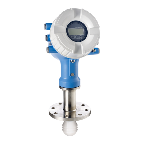
- Page 2 Micropilot NMR81 Order code: XXXXX-XXXXXX Ser. no.: XXXXXXXXXXXX Ext. ord. cd.: XXX.XXXX.XX Serial number www.endress.com/deviceviewer Endress+Hauser Operations App A0023555 Endress+Hauser...
-
Page 3: Table Of Contents
Micropilot NMR81 Table of contents Table of contents About this document ............. . 3 Document conventions . - Page 4 About this document Micropilot NMR81 CAUTION This symbol alerts you to a dangerous situation. Failure to avoid this situation can result in minor or medium injury. NOTICE This symbol contains information on procedures and other facts which do not result in personal injury.
- Page 5 Micropilot NMR81 About this document Preferred Procedures, processes or actions that are preferred Forbidden Procedures, processes or actions that are forbidden Indicates additional information Reference to documentation Reference to graphic Notice or individual step to be observed Series of steps...
-
Page 6: Documentation
For an overview of the scope of the associated Technical Documentation, refer to the following: • W@M Device Viewer (www.endress.com/deviceviewer): Enter the serial number from nameplate • Endress+Hauser Operations App: Enter the serial number from the nameplate or scan the 2D matrix code (QR code) on the nameplate 1.2.1 Technical Information (TI) -
Page 7: Basic Safety Instructions
Micropilot NMR81 Basic safety instructions Basic safety instructions Requirements for the personnel The personnel must fulfill the following requirements for its tasks: ‣ Trained, qualified specialists must have a relevant qualification for this specific function and task. ‣ Are authorized by the plant owner/operator. -
Page 8: Workplace Safety
The measuring system meets the legal requirements of the applicable EC guidelines. These are listed in the corresponding EC Declaration of Conformity together with the standards applied. Endress+Hauser confirms successful testing of the device by affixing to it the CE mark. Endress+Hauser... -
Page 9: Product Description
• Are the goods undamaged? • Do the nameplate data match the ordering information on the delivery note? • If required (see nameplate): Are the Safety Instructions (XA) enclosed? If one of these conditions is not satisfied, contact your Endress+Hauser Sales Center. Endress+Hauser... -
Page 10: Product Identification
): All information about the measuring device is displayed. • Enter the serial number from the nameplates into the Endress+Hauser Operations App or scan the 2-D matrix code (QR code) on the nameplate with the Endress+Hauser Operations App: all the information for the measuring device is displayed. -
Page 11: Installation
Micropilot NMR81 Installation Installation Installation conditions 5.1.1 Mounting position General conditions • Do not install in the centre of the tank. • Do not install above a filling stream. • Avoid any tank installations (e.g. limit switches, temperature probes) within in the signal beam. - Page 12 Installation Micropilot NMR81 Inner nozzle diameter (ØD) Maximum nozzle length (H Antenna AB Antenna AC: Antenna AD: 50mm/2" 80mm/3" 100mm/4" > 45 mm (1.77 in); ≤ 75 mm (2.95 in) 600 mm (24 in) > 75 mm (2.95 in); ≤ 95 mm (3.74 in)
- Page 13 Micropilot NMR81 Installation 5.1.3 Vertical alignment of the 50mm(2") and 80mm (3") antenna For optimum measuring accuracy the antenna must be installed at right angles to the medium surface. An adjustable seal is available for the alignment. Adjustable seal ød øD...
- Page 14 Installation Micropilot NMR81 5.1.4 Vertical alignment of the 100mm(4") antenna For optimum measuring accuracy the antenna must be installed at right angles to the medium surface. For this purpose the 100mm(4") antenna always has an alignment unit. A level tool indicating the correct alignment is attached to the alignment tool.
-
Page 15: Electrical Connection
Micropilot NMR81 Electrical connection Electrical connection Terminal assignment POWER POWER G1 N AC 85...264 V G3 L A0026372 4 Terminal compartment (typical example) and ground terminals Terminal area A/B/C/D (slots for I/O modules) Module: Up to four I/O modules, depending on the order code •... - Page 16 Electrical connection Micropilot NMR81 Terminal area G (for Low voltage DC power supply) • G1: L- • G2: not connected • G3: L+ Terminal area: Protective ground Module: Protective ground connection (M4 screw) A0018339 5 Terminal area: Protective ground 6.1.1...
- Page 17 Micropilot NMR81 Electrical connection Low voltage DC power supply: Operational value: 24 to 55 V (- 20 % + 15 %) = 19 to 64 V Power consumption Maximum power varies depending on the configuration of the modules. The value shows maximum apparent power, select the applicable cables accordingly. The actual consumed effective power is 12 W.
- Page 18 Electrical connection Micropilot NMR81 6.1.2 Remote display and operating module DKX001 81 82 83 84 F1 F2 F3 F4 POWER A0037025 6 Connection of the remote display and operating module DKX001 to the Tank Gauging device (NMR8x, NMS8x or NRF8x)
- Page 19 Micropilot NMR81 Electrical connection 6.1.3 HART Ex i/IS interface POWER A0033414 Orange LED: indicates data communication This interface always operates as the main HART master for connected HART slave transmitters. The Analog I/O modules, on the other hand, can be configured as a HART master or slave →...
- Page 20 Electrical connection Micropilot NMR81 6.1.4 Slots for I/O modules The terminal compartment contains four slots (A, B, C and D) for I/O modules. Depending on the device version (ordering features 040, 050 and 060) these slots contain different I/O modules. The slot assignment for the device at hand is indicated on a label attached to the back cover of the display module.
- Page 21 Micropilot NMR81 Electrical connection 6.1.5 Terminals of the "Modbus" module, "V1" module or "WM550" module 1 2 3 4 D1-4 1 2 3 4 POWER A1-4 A0031200 7 Designation of the "Modbus", "V1" or "WM550" modules (examples); depending on the device version these modules may also be in slot B or C.
- Page 22 Electrical connection Micropilot NMR81 Terminals of the "V1" and "WM550" module Designation of the module in the operating menu: V1 X1-4 or WM550 X1-4; (X = A, B, C or • X1 • Terminal name: S • Description: Cable shielding connected via a capacitor to EARTH •...
- Page 23 Micropilot NMR81 Electrical connection 6.1.6 Connection of the "Analog I/O" module for passive usage • In the passive usage the supply voltage for the communication line must be supplied by an external source. • The wiring must be in accordance with the intended operating mode of the Analog I/O module;...
- Page 24 Electrical connection Micropilot NMR81 "Operating mode" = "4..20mA input" or "HART master+4..20mA input" POWER POWER – A0027933 9 Passive usage of the Analog I/O module in the input mode Power supply External device with 4...20mA and/or HART signal output...
- Page 25 Micropilot NMR81 Electrical connection "Operating mode" = "HART master" POWER POWER – A0027934 10 Passive usage of the Analog I/O module in the HART master mode Power supply Up to 6 external devices with HART signal output Endress+Hauser...
- Page 26 Electrical connection Micropilot NMR81 6.1.7 Connection of the "Analog I/O" module for active usage • In the active usage the supply voltage for the communication line is supplied by the device itself. There is no need of an external power supply.
- Page 27 Micropilot NMR81 Electrical connection "Operating mode" = "4..20mA input" or "HART master+4..20mA input" POWER POWER A0027935 12 Active usage of the Analog I/O module in the input mode External device with 4...20mA and/or HART signal output Endress+Hauser...
- Page 28 Electrical connection Micropilot NMR81 "Operating mode" = "HART master" POWER POWER A0027936 13 Active usage of the Analog I/O module in the HART master mode Up to 6 external devices with HART signal output The maximum current consumption for the connected HART devices is 24 mA (i.e. 4 mA per device if 6 devices are connected).
- Page 29 Micropilot NMR81 Electrical connection 6.1.8 Connection of a RTD A0026371 4-wire RTD connection 3-wire RTD connection 2-wire RTD connection Screened cable must be used for the connection of the RTD. Endress+Hauser...
- Page 30 Electrical connection Micropilot NMR81 6.1.9 Terminals of the "Digital I/O" module 1 2 3 4 5 6 7 C1-2 C3-4 1 2 3 4 POWER A1-2 A3-4 A0026424 14 Designation of the digital inputs or outputs (examples) • Each Digital IO Module provides two digital inputs or outputs.
-
Page 31: Connecting Requirements
Micropilot NMR81 Electrical connection Connecting requirements 6.2.1 Cable specification Terminals Wire cross section 0.2 to 2.5 mm (24 to 13 AWG) Use for terminals with function: Signal and power supply • Spring terminals (NMx8x-xx1...) • Screw terminals (NMx8x-xx2...) Wire cross section max. 2.5 mm... -
Page 32: Ensuring The Degree Of Protection
Electrical connection Micropilot NMR81 Ensuring the degree of protection To guarantee the specified degree of protection, carry out the following steps after the electrical connection: Check that the housing seals are clean and fitted correctly. Dry, clean or replace the seals if necessary. -
Page 33: Commissioning
Micropilot NMR81 Commissioning Commissioning Operating methods 7.1.1 Operation via the local display A0028345 15 Display and operating elements Liquid crystal display (LCD) Optical keys; can be operated through the cover glass. Endress+Hauser... - Page 34 Commissioning Micropilot NMR81 Standard view (measured value display) X X X X X X X 4841.00 A0028317 16 Typical appearance of the standard view (measured value display) Display module Device tag Status area Display area for measured values Display area for measured value and status symbols...
- Page 35 Display area for navigation 7.1.2 Operation via service interface and FieldCare/DeviceCare A0023737 18 Operation via service interface Service interface (CDI = Endress+Hauser Common Data Interface) Commubox FXA291 Computer with "FieldCare" or "DeviceCare" operating tool and "CDI Communication FXA291" COM DTM Endress+Hauser...
-
Page 36: Terms Related To Tank Measurement
Commissioning Micropilot NMR81 Terms related to tank measurement A0029794 19 Terms related to radar tank measurement Gauge reference height Empty Datum plate Ullage level Level Tank reference height Measured distance Dipping reference Endress+Hauser... -
Page 37: Initial Settings
Micropilot NMR81 Commissioning Initial settings 7.3.1 Setting the display language Setting the display language via the display module While in the standard view (), press "E". If required, select Keylock off from the context menu and press "E" again. The Language parameter appears. - Page 38 Commissioning Micropilot NMR81 Use the following parameters to set the date and time: Year, Month, Day, Hour, Minutes. Go to the Set date parameter and select the Confirm time option. The real-time clock is set to the current date and time.
-
Page 39: Configuration Of The Radar Measurement
Micropilot NMR81 Commissioning Configuration of the radar measurement 7.4.1 Basic settings Submenu: Setup Parameter Meaning / Action Device tag Define a name to identify the measuring point within the plant. Units preset Select a set of units for length, pressure and temperature. -
Page 40: Configuration Of The Inputs
Commissioning Micropilot NMR81 Configuration of the inputs 7.5.1 Configuration of the HART inputs 1 2 3 4 5 6 7 8 C1-3 C4-8 1 2 3 4 5 6 7 8 POWER B1-3 B4-8 A0032955 20 Possible terminals for HART loops... - Page 41 Micropilot NMR81 Commissioning 1) 2) Submenu: Setup → Advanced setup → Input/output → HART devices → HART Device(s) Parameter Meaning / Action Output pressure • If the device measures a pressure: Select which of the HART variables (PV, SV, TV or QV) contains the pressure.
- Page 42 Commissioning Micropilot NMR81 7.5.2 Configuration of the 4-20mA inputs 1 2 3 4 5 6 7 8 C1-3 C4-8 1 2 3 4 5 6 7 8 POWER B1-3 B4-8 A0032464 21 Possible locations of the Analog I/O modules, which can be used as a 4-20mA input. The order code of the device determines which of these modules is actually present.
- Page 43 Micropilot NMR81 Commissioning I [mA] 20mA 100% A0029264 22 Scaling of the 4-20mA input to the process variable Input value in mA Process value Endress+Hauser...
- Page 44 Commissioning Micropilot NMR81 7.5.3 Configuration of a connected RTD 1 2 3 4 5 6 7 8 1 2 3 4 5 6 7 8 C1-3 C4-8 1 2 3 4 5 6 7 8 1 2 3 4 5 6 7 8...
- Page 45 Micropilot NMR81 Commissioning A0029269 Datum plate Probe position Endress+Hauser...
- Page 46 Commissioning Micropilot NMR81 7.5.4 Configuration of the digital inputs 1 2 3 4 5 6 7 C1-2 C3-4 1 2 3 4 POWER A1-2 A3-4 A0026424 24 Possible locations of the Digital I/O modules (examples); the order code defines the number and location of digial input modules.
- Page 47 Micropilot NMR81 Commissioning A0029262 "Operating mode" = "Input passive" "Operating mode" = "Input active" State of the external switch Internal state of the DIO module Contact type = Normally open Contact type = Normally closed Open Inactive Active Closed Active...
-
Page 48: Linking Measured Values To Tank Variables
Commissioning Micropilot NMR81 Linking measured values to tank variables Measured values must be linked to tank variables before they can be used in the Tank Gauging application. Depending on the application not all these parameters will be relevant in a given situation. -
Page 49: Configuration Of The Limit Evaluation
Micropilot NMR81 Commissioning Configuration of the limit evaluation A limit evaluation can be configured for up to 4 tank variables. The limit evaluation generates an alarm if the value exceeds an upper limit or falls below a lower limit, respectively. The limit values can be defined by the user. - Page 50 Commissioning Micropilot NMR81 To configure an alarm, assign appropriate values to the following parameters: Submenu: Setup → Advanced setup → Application → Alarm → Alarm 1 to 4 Parameter Meaning / Action Alarm mode • Off No alarms are generated.
-
Page 51: Configuration Of The Signal Output
Micropilot NMR81 Commissioning Configuration of the signal output 7.8.1 Analog output (4...20mA) 1 2 3 4 5 6 7 8 C1-3 C4-8 1 2 3 4 5 6 7 8 POWER B1-3 B4-8 A0032464 26 Possible locations of the Analog I/O modules, which can be used as an analog output. The order code of the device determines which of these modules is actually present. - Page 52 Commissioning Micropilot NMR81 7.8.2 HART output This section is only valid for Operating mode = HART slave +4..20mA output. Setup → Advanced setup → Communication → HART output → Configuration Parameter Meaning / Action System polling address Set the HART communication address of the device.
- Page 53 Micropilot NMR81 Commissioning 7.8.3 Modbus, V1 or WM550 output 1 2 3 4 D1-4 1 2 3 4 POWER A1-4 A0031200 27 Possible locations of the Modbus or V1 modules (examples); depending on the device version these modules may also be in slot B or C .
- Page 56 *71497756* 71497756 www.addresses.endress.com...