
Related Manuals for Endress+Hauser Prothermo NMT532


Summary of Contents for Endress+Hauser Prothermo NMT532
- Page 1 Products Solutions Services BA01032G/00/EN/22.19 71440635 2019-05-23 Operating Instructions Prothermo NMT532 Average temperature device...
- Page 2 Prothermo NMT532 Order code: XXXXX-XXXXXX Ser. no.: XXXXXXXXXXXX Ext. ord. cd.: XXX.XXXX.XX Serial number www.endress.com/deviceviewer Endress+Hauser Operations App A0023555 Endress+Hauser...
-
Page 3: Table Of Contents
Operational safety ..... . 9 10.2 Endress+Hauser services ....65 Product safety . -
Page 4: About This Document
About this document Prothermo NMT532 About this document Document function These Operating Instructions contain all the information that is required during various phases of the life cycle of the device: from product identification, incoming acceptance and storage, to mounting, connection, operation and commissioning through to troubleshooting, maintenance and disposal. - Page 5 Prothermo NMT532 About this document 1.2.3 Tool symbols Symbol Meaning Torx screwdriver A0013442 Flat blade screwdriver A0011220 Phillips screwdriver A0011219 Allen key A0011221 Open-ended wrench A0011222 1.2.4 Symbols for certain types of information Symbol Meaning Permitted Procedures, processes or actions that are permitted...
- Page 6 About this document Prothermo NMT532 1.2.5 Symbols in graphics Symbol Meaning 1, 2, 3 ... Item numbers … Series of steps A, B, C, ... Graphics A-A, B-B, C-C, ... Cross-sections Hazardous area Indicates the hazardous area Safe area (non-hazardous area) Indicates the non-hazardous area 1.2.6...
-
Page 7: Documentation
• The W@M Device Viewer: Enter the serial number from the nameplate (www.endress.com/deviceviewer). • The Endress+Hauser Operations App: Enter the serial number from the nameplate or scan the 2-D matrix code (QR code) on the nameplate. 1.3.1... -
Page 8: Basic Safety Instructions
Basic safety instructions Prothermo NMT532 Basic safety instructions Requirements for personnel The personnel for installation, commissioning, diagnostics and maintenance must fulfill the following requirements: ‣ Be specialists who are trained and have a relevant qualification for this specific function and task. -
Page 9: Operational Safety
Modifications to the device Unauthorized modifications to the device are not permitted and can lead to unforeseeable dangers: ‣ If modifications are nevertheless required, contact your Endress+Hauser Sales Center. Repair To ensure continued operational safety and reliability: ‣ Carry out repairs on the device only if they are expressly permitted. -
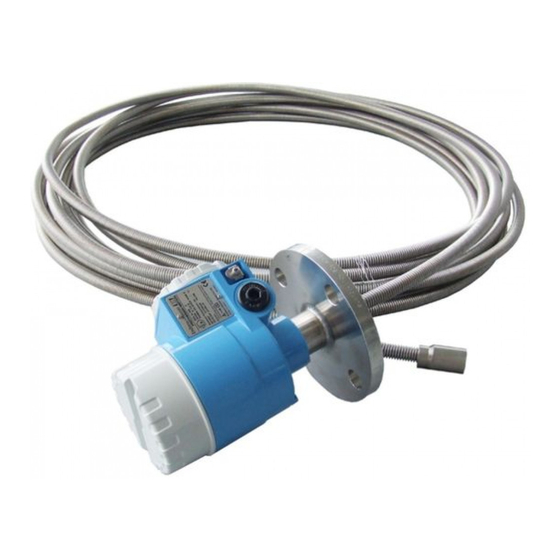
Page 10: Product Description
Prothermo NMT532 Product description Product design Prothermo NMT532 is a multi-spot Pt100 average thermometer combined with a local HART signal converter to meet the demand of temperature measurement for inventory control applications. NMT532 consists of Max. 6 temperature elements which have different length with fixed (2m or 3m) interval. - Page 11 • NPS 2" Cl.150 RF, 304 flange ASME B16.5 • DN50 PN10 B1, 304 flange EN1092-1 (DIN2527 C) CE approval By attaching the CE mark, Endress+Hauser confirms that the instruments have passed the required tests. External standards EN 60529 Protection class of housing (IP-code)
-
Page 12: Description Of Functions
Product description Prothermo NMT532 Description of functions The NMT532 is compact and economical. The average temperature sensor consists of six Pt100 elements which have fixed interval of 2 m (6.57 ft) or 3 m (9.84 ft) from the next sensor. Temperature data is transmitted to the NRF560, NRF81, NMS5, NMS8x, or NMR81x via an intrinsically safe (i.s.) 2-wire local HART signal. - Page 13 Prothermo NMT532 Product description 3.3.2 NMT532 Ex ia and Micropilot FMR S-series combination Typical application of NMT532 converter + temperature probe Temperature and level measurement with data collection and calculations via NRF81 allows for optimal inventory control. Basic functionality of NMT532 is displayed and configured on NRF81.
-
Page 14: Incoming Acceptance And Product
• Do the nameplate data match the ordering information on the delivery note? • If required (see nameplate): Are the Safety Instructions (XA) enclosed? If any one of these conditions is not met, contact your Endress+Hauser Sales Center. Product identification The following options are available for the identification of the device: •... - Page 15 < 120 mA Pi < 1 W Ci = 7.9 nF Li = 48 µH IP65, NEMA 4X Warning: Don’t modify parts and circuits of this instrument. Endress+Hauser Yamanashi Co., Ltd Yamanashi 406-0846 0044 Made in Japan NP-2560-6 A0038588 ...
-
Page 16: Manufacturer Contact Address
Évitez la charge électrostatique sur la surface plastique. Install per control drawing Installation par dessin de contrôle C: Ex462-875-2 C: Ex462-875-2 US: Ex461-852-2 US: Ex461-852-2 Endress+Hauser Yamanashi Co., Ltd Endress+Hauser Yamanashi Co., Ltd Yamanashi 406-0846 Yamanashi 406-0846 0044 0044 Made in Japan... - Page 17 Prothermo NMT532 Incoming acceptance and product identification NOTICE Risk of injury ‣ Transport the measuring device to the measuring point in its original packaging. ‣ Take into account the center of gravity of the device in order to avoid unintended tilting.
-
Page 18: Installation
Installation Prothermo NMT532 Installation Dimensions of NMT532 142.5 (5.61) Ø10 (0.39) Ø26 (1.02) A0038592 8 Dimensions of NMT532. Unit of measurement mm (in) SUS304 Temperature probe (SUS316L) (see tips below.) Bottom hook (SUS316) SUS316 The specifications of temperature probe vary depending on the tank height. -
Page 19: Position Of Nmt532 Element No. 1 Based On The Installation Method
Prothermo NMT532 Installation Position of NMT532 element No. 1 based on the installation method A0038597 9 Element No. 1 position Height below the flange to the end of the temperature probe for all types of NMT532 Unpacking Unpack NMT532 with multiple people. If one person unpacks NMT532, the temperature probe may become bent or twisted. -
Page 20: Flexible Tube Handling
Installation Prothermo NMT532 Flexible tube handling Do not hold the flexible tube at a single point and lift the sensor. This may cause the system to malfunction. A0038593 11 Flexible tube When winding the flexible tube, keep the diameter of the tube at a minimum of 600 mm (23.62 in) or more. -
Page 21: Mounting Nmt532 On Fixed Roof Tank
Prothermo NMT532 Installation Mounting NMT532 on fixed roof tank There are three ways to install NMT532 onto a fixed roof tank: • Top anchor method • Thermo well method • Anchor weight method If a heating coil is attached to the bottom of the tank, the clearance between the bottom hook of the flexible tube and the bottom of the tank may vary depending on the type of heating coil. - Page 22 Installation Prothermo NMT532 Top anchor attachment procedure The flexible tube must be lowered carefully without overbending and scratching the inner edge of the nozzle hole. 1. Insert the flexible tube into a gasket and lower the flexible tube from the nozzle at the top of the tank.
- Page 23 Prothermo NMT532 Installation 12. Rotate the nuts clockwise until the top anchor' s spring is 35 to 37 mm (1.38 to 1.46 in). A0038513 15 Top anchor installation 2. Unit of measurement mm (in) 13. Cover the top anchor.
- Page 24 Installation Prothermo NMT532 5.5.2 Thermo well method The flexible tube is inserted into a thermo well with a diameter of 80.8 mm (2 in) or more. Ø26 (1.02) A0038599 16 Thermo well. Unit of measurement mm (in) Electrical compartment...
- Page 25 Prothermo NMT532 Installation 5.5.3 Anchor weight method The flexible tube is fixed with an anchor weight. Ø120(4.72) 1000(39.37) Ø26 (1.02) A0038600 17 Anchor weight 400 mm (15.57 in) (Clearance below bottom of the hook to the bottom of the tank)
- Page 26 Installation Prothermo NMT532 3. Put the tensioning wire [4] through the anchor weight hook [5] twice and also tie the other end to the bottom hook [3]. 4. Wind the provided wire [1] around both ties of the hooks to secure the tensioning wire.
- Page 27 Prothermo NMT532 Installation 5.5.5 Top anchor method The flexible tube is installed in a fixed pipe and fixed with the top anchor. NMS5 or NMS8x and NMT532 can be mounted in the same fixed pipe. Ø26 (1.02) A0038602 19 Floating roof tank.
- Page 28 Installation Prothermo NMT532 5.5.6 Thermo well method The flexible tube is inserted into a thermo well in the fixed pipe. Ø26 (1.02) A0038603 20 Thermo well method. Unit of measurement mm (in) Stilling pipe, ⌀ 50.8 mm (2 in) or more, depending on specifications 400 mm (15.57 in), Clearance of bottom hook...
- Page 29 Prothermo NMT532 Installation 5.5.7 Guide ring and anchor weight method The flexible tube is fixed with a guide ring and an anchor weight. Ø26 (1.02) A0038604 21 Guide ring and anchor weight. Unit of measurement mm (in) 400 mm (15.57 in), Clearance of bottom hook 500 to 1 000 mm (19.69 to 39.37 in)
- Page 30 Installation Prothermo NMT532 4. Put the tensioning wire through the anchor weight hook twice and also tie the other end to the bottom hook. 5. Wind the provided wire around both ties of the hooks to secure the tensioning wire.
- Page 31 Prothermo NMT532 Installation 5.5.8 Mounting on pressurized tank Pressurized tank is required to install a thermo well to protect the probe from the pressure. A0038605 22 Thermo well for a pressurized tank NMS8x / NMS5 Ball valve Measuring wire...
-
Page 32: Electrical Connection
Electrical connection Prothermo NMT532 Electrical connection Terminal connection 6.1.1 NMT532 (Ex ia) intrinsically safe connection NMT532, which uses intrinsically safe local HART communication, must be connected to the device' s intrinsically safe terminal to be connected. Refer to the intrinsic safety regulations for establishing wiring and field device layout. - Page 33 Prothermo NMT532 Electrical connection 6.1.2 NMS5 (Ex d [ia]) intrinsically safe connection The intrinsically safe NMT532 must be connected to the intrinsically safe local HART terminal on NMS5. HOIST STOP A0038529 25 NMS5 terminal Power supply AC 85: 264 V50/60 Hz or DC20: 62 V AC20: 55 V Non-intrinsically safe HART communication: NRF, etc.
-
Page 34: Nrf590 Terminals
Electrical connection Prothermo NMT532 POWER A0038531 26 NMS8x terminal for NMT532 H+ terminal H- terminal NRF590 terminals NRF590 has three sets of intrinsically safe local HART terminals. OPT1 OPT2 OPT3 OPT4 A0038533 27 NRF590 (intrinsically safe) terminals A HART sensor (mutually connected as a single HART fieldbus loop on the inside) -
Page 35: Grounding
Prothermo NMT532 Electrical connection 01 L/+ 02 /N- 04 A1/+ 05 A2/- 06 B1/+ 07 B2/- 00 S 08 C1 09 C2 10 C3 11 C4 12 C5 13 C6 14 C7 15 C8 A0038534 28 NRF590 (TIIS flameproof) terminal... -
Page 36: Adjustment And Settings
7.1.1 Endress+Hauser tank gauging instrument NMT532 is developed and designated primarily to work with Endress+Hauser tank gauging host instruments NRF590, NMS5, NMS8x, NMR8x, or NRF81. Temperature information is transmitted on a two wire intrinsically safe local HART loop to the host instrument. -
Page 37: Device Configuration: Nms5/Nms7
Prothermo NMT532 Adjustment and settings Device configuration: NMS5/NMS7 NMS5/NMS7 are specifically designed to recognize NMT532 as HART Master. Terminals 24 and 25 of NMT532 and NMS5/NMS7 are connected with a local HART cable. Connection between NMS5/NMS7 and NMT532 is required for Ex Approval refer to "Terminal connection."... - Page 38 Adjustment and settings Prothermo NMT532 Code Display Details GVH480 Diagnostic Displays error code messages. Refer to the error code chart in this manual. GVH482 Element number The number of elements installed on the temperature measurement tube is entered. GVH485 Type of interval Sets measurement element intervals.
-
Page 39: Configuring Nmt532 With Nms8X/Nmr8X/Nrf81
Prothermo NMT532 Adjustment and settings Configuring NMT532 with NMS8x/NMR8x/NRF81 NMS8x, NMR8x and NRF81 are specifically designed to recognize NMT532 as HART Master. Terminals E1 and E2 or B3 and C3 of NMR8x, NRF81 and NMS8x are connected to NMT532 with a local HART cable. - Page 40 Adjustment and settings Prothermo NMT532 Vapor temperature Item Details Navigation Operation → Temperature → Vapor temperature Description Displays the measured vapor temperature. Additional information Read access: Operator Write access: - Display of element temperature 1-24 Item Details Navigation Operation → Temperature →NMT element values → Element temperature →...
- Page 41 Prothermo NMT532 Adjustment and settings 7.4.2 NMS8x/NMR8x/NRF81 configuration Below are NMT532-related parameters. For details on the operation of NMS8x, NMR8x and NRF81, see their respective operating instructions. The following parameters can be checked from the display accessed through the Main Menu → Expert → Input/Output → HART device → HART device(s) [MenuName].
- Page 42 Adjustment and settings Prothermo NMT532 Access code Item Details Navigation Expert → Input/Output → HART device → HART device(s) [MenuName] → HART Device configuration → Access code (14714) Conditions Configure device? = Yes Description Displays the access code. Input range...
- Page 43 Prothermo NMT532 Adjustment and settings Temp element open Item Details Navigation Expert → Input/Output → HART device → HART device(s) [MenuName] → HART device configuration → Temp elem. open (14732) Description Configures the error code for when an element is open.
- Page 44 Adjustment and settings Prothermo NMT532 Element interval Item Details Navigation Expert → Input/Output → HART device → HART device(s) [MenuName] → HART device configuration → Element interval (14743) Conditions Kind of interval: Equal Description Sets the interval of each element.
- Page 45 Prothermo NMT532 Adjustment and settings Element position Item Details Navigation Expert → Input/Output → HART device → HART device(s) → NMT device configuration → Element configuration → Element position (14738) Description Adjusts the element position. Input unit Numerical value Factory setting...
-
Page 46: Operation
Operation Prothermo NMT532 Operation The following configuration uses FieldCare. WARNING Modification of modules Changing the jumper setting by disassembling the internal module of NMT532 may invalidate the accuracy of the calibration that was performed at the factory. It may also cause serious accidents. - Page 47 Prothermo NMT532 Operation Code Display Details (Liquid level) Range 0 to 99 999 mm Displays the liquid level inside the tank as configured by a level gauge. If a level gauge is not connected, a directly input liquid level can be used as a device test.
- Page 48 Operation Prothermo NMT532 Standard calculation method Regardless of the shape of the tank, average temperature is calculated using the following formula: Formula: (T1 + T2 + T3) / Number of elements in liquid phase = Average temperature (3.5 °C (38.3 °F) + 3.0 °C (37.4 °F) + 2.0 °C (35.6 °F)) / 3 = 2.83 °C (37.1 °F) A0038546 ...
- Page 49 Prothermo NMT532 Operation Advanced calculation method 2 Average temperature is calculated by adding a corrective factor for unequal volume distribution. Formula: (3.5 °C (38.3 °F) x 2 + 3.0 °C (37.4 °F) x 3 + 2.0 °C (35.6 °F) x 4) / (2 + 3 + 4) = 2.67 °C (36.8 °F)
- Page 50 Operation Prothermo NMT532 Spot temperature of the display array When some temperature elements (resistance and material) are located in each input cable in the probe; average calculation is performed based on sum of submerged temperature element value/total number of temperature element submerged.
- Page 51 Prothermo NMT532 Operation 8.3.5 Element position 2: VH46 to VH49 (VH40 to VH45 are not available in NMT532) Code Display Details VH46 Hysteresis Width Item type Read / Write (Hysteresis width) Default 10 mm (0.39 in) Range 0 to 99 999 mm Sets the hysteresis of an element switch position.
- Page 52 Operation Prothermo NMT532 Code Display Details Range 0 to 99 999 mm A0038551 37 Liquid offset VH48 gas offset 300 mm (11.81 in) (Default) To NMT532 converter Temperature element Gas phase Exclusion range (see Note) Level Liquid phase To tank bottom ...
- Page 53 Prothermo NMT532 Operation 8.3.6 Advanced temperature: VH50-VH59 Code Display Details VH53 Element Point Item type Selection (Element point) Default Selection 0-15 (Element No.1 = 0, Element No. 16 = 15) Selects the number of elements for "Advanced" average temperature calculations in VH26. The positions of the selected elements are displayed in VH54 "Element Position,"...
- Page 54 Operation Prothermo NMT532 8.3.8 Temperature adjustment: VH70-VH79 Code Display Details VH70 Element Select Item type Selection (Element number Range 0 to 19 assignment) The element number for performing temperature adjustments is selected (Element 0-15 = Element 1-16, 19 = Reference 100 Ω...
- Page 55 Prothermo NMT532 Operation Code Display Details The element conversion formula is selected for when another brand' s average temperature probe is connected to the NMT532. CAUTION Changing the parameters: NMT532 is comprised of spot, element array and PT100 element types.
- Page 56 Operation Prothermo NMT532 Code Display Details #5 element open #5 element short #6 element open #6 element short #0 element over range Memory defect (ROM) Element exposed (liquid level below #1 element position) Memory defect (RAM) Memory defect (EEROM) Code...
- Page 57 Prothermo NMT532 Operation Code Display Details • Selects the level display unit. This applies to the display of VH02 "Liquid level" and VH50 "WB". Based on the configuration of HART, the available level units are: ft. (HART code: 44), m (HART code: 45), inch (HART code: 47) and mm (HART code: 49).
- Page 58 Operation Prothermo NMT532 Code Display Details Range 0 to 16 777 214 Screen used for distinguishing the device ID when the NMT532 connects to a HART communication loop. NOTICE Device ID and HART address: When a device ID is changed, a communication error may occur due to inappropriate device ID and HART address combination.
-
Page 59: Wb (Water Bottom) Level Input From Host
Prothermo NMT532 Operation WB (water bottom) level input from host This function is available in V1.53 and later versions. If the specification does not have a WB probe, VH50 WB can be entered manually from the HART Master. This function is available for specifications that do not have a WB probe. It will not be applied to multi-element calculations. -
Page 60: Temperature Element Near The Tank Bottom
Operation Prothermo NMT532 A0038558 39 Screen 2 VH number Temperature element near the tank bottom This function is available in V1.53 and later versions. Temperature elements that are less than 1 m (3.28 ft) from the tank bottom are handled as shown in the following table in average liquid temperature calculations. - Page 61 Prothermo NMT532 Operation 1500 (59.06) 1000 (39.37) 500 (19.69) A0038559 40 Example of temperature elements near the tank bottom Temperature element 1 Temperature element 2 Case 1 Case 2 Case 3 Case 4 • Case 1: If the liquid level is within this range, temperature element a will not be used in average liquid temperature calculations.
-
Page 62: Write-Protection Switch
Operation Prothermo NMT532 Write-protection switch (write-protection plug) When the write-protection switch in software version 1.53 or later is used, all parameters become write protected. In PTB specifications, this comes with the product. Do not disconnect and reconnect while the power is on. -
Page 63: Diagnostics And Troubleshooting
Prothermo NMT532 Diagnostics and troubleshooting Diagnostics and troubleshooting System error messages Code Text Description Remedy No Error presence There is no error. No action is required. Common line open The common line is open. Check the module' s connections, and check the impedance between the common cable (white/black or white/purple) and the cable for the #1 temperature element (brown). - Page 64 Diagnostics and troubleshooting Prothermo NMT532 Code Text Description Remedy Memory defect Data memory is defective. Replace the module. (RAM) Memory defect Non-volatile data memory is defective. Replace the module. (EEROM) Error codes appear on the screen when FieldCare is properly connected. For methods and descriptions of error display on a host device, see documents for NRF590, MS5, NMS7 or NMS8x.
-
Page 65: Maintenance
10.2 Endress+Hauser services Endress+Hauser offers a wide variety of services for maintenance such as recalibration, maintenance service or device tests. Your Endress+Hauser Sales Center can provide detailed information on the services. -
Page 66: Repair
General information on repairs 11.1.1 Repair concept The Endress+Hauser repair concept assumes that the devices have a modular design and that repairs can be done by the Endress+Hauser Service Department or specially trained customers. Spare parts are included in appropriate kits. They contain the related replacement instructions. -
Page 67: Return
The device must be returned if it is in need of repair or a factory calibration, or if the wrong device has been delivered or ordered. According to legal regulations, Endress+Hauser, as an ISO-certified company, is required to follow certain procedures when handling returned products that have come into contact with measured materials. -
Page 68: Accessories
Accessories Prothermo NMT532 Accessories 12.1 Device-specific accessories 12.1.1 Anchor weight (high profile) This anchor weight was designed for the converter + temperature probe version. Even when an anchor weight is used for the installation, the bottom element (bottom point temperature measurement position) will be set at approx. 500 mm above the tank bottom. - Page 69 Prothermo NMT532 Accessories 12.1.2 Anchor weight (low profile) The low-profile anchor weight is mainly designed to secure a WB probe for measuring the WB measurement range accurately. It can also be used as an installation attachment for the converter + temperature probe version when trying to install a small tank nozzle (50A (2") or smaller) that is in use.
- Page 70 Accessories Prothermo NMT532 12.1.4 Top anchor The standard threaded connection for a top anchor is an NPT1 or R1 threaded connection. It can accommodate different thread sizes, materials and special specifications. A joint flange is also possible. 52 (2.05) A0038538 ...
-
Page 71: Index
Prothermo NMT532 Index Index Symbols Application ....... . . 8 Safety Instructions Basic . - Page 72 www.addresses.endress.com...