
Related Manuals for Endress+Hauser Prothermo NMT81


Summary of Contents for Endress+Hauser Prothermo NMT81
- Page 1 Products Solutions Services BA02094G/00/EN/01.21 71517024 2021-06-08 Valid as of version 01.00.00.zz (Device firmware) Operating Instructions Prothermo NMT81 Tank Gauging...
- Page 2 Prothermo NMT81 Order code: XXXXX-XXXXXX Ser. no.: XXXXXXXXXXXX Ext. ord. cd.: XXX.XXXX.XX Serial number www.endress.com/deviceviewer Endress+Hauser Operations App A0023555 Endress+Hauser...
-
Page 3: Table Of Contents
12.1 Maintenance tasks ....102 12.2 Endress+Hauser services ....102 NMT81 (Ex ia) intrinsically safe connection . - Page 4 Table of contents Prothermo NMT81 Accessories ..... . 105 14.1 Device-specific accessories ....105 Index .
-
Page 5: About This Document
Prothermo NMT81 About this document About this document Document function These Operating Instructions contain all the information that is required in various phases of the life cycle of the device: from product identification, incoming acceptance and storage, to mounting, connection, operation and commissioning through to troubleshooting, maintenance and disposal. - Page 6 About this document Prothermo NMT81 Flat blade screwdriver Torx screwdriver Allen key Open-ended wrench 1.2.4 Symbols for certain types of information and graphics Permitted Procedures, processes or actions that are permitted Preferred Procedures, processes or actions that are preferred Forbidden...
-
Page 7: Documentation
For an overview of the scope of the associated Technical Documentation, refer to the following: • W@M Device Viewer (www.endress.com/deviceviewer): Enter the serial number from nameplate • Endress+Hauser Operations App: Enter the serial number from the nameplate or scan the 2D matrix code (QR code) on the nameplate 1.3.1 Technical Information (TI) -
Page 8: Registered Trademarks
About this document Prothermo NMT81 Registered trademarks FieldCare ® Registered trademark of the Endress+Hauser Process Solutions AG, Reinach, Switzerland Endress+Hauser... -
Page 9: Basic Safety Instructions
Prothermo NMT81 Basic safety instructions Basic safety instructions Requirements for the personnel The personnel for installation, commissioning, diagnostics and maintenance must fulfill the following requirements: ‣ Trained, qualified specialists must have a relevant qualification for this specific function and task. -
Page 10: Product Safety
Basic safety instructions Prothermo NMT81 Conversions to the device Unauthorized modifications to the device are not permitted and can lead to unforeseeable dangers. ‣ If, despite this, modifications are required, consult with the manufacturer. Repair To ensure continued operational safety and reliability, ‣... -
Page 11: Product Description
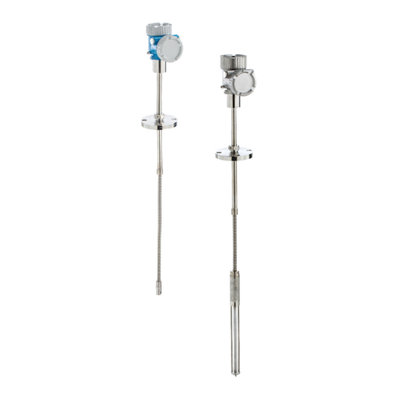
A0042800 1 Design of Prothermo NMT81 NMT81 with water bottom (WB) NMT81 without water bottom (WB) Converter... -
Page 12: Incoming Acceptance And Product
• Enter the serial number from the nameplates into the Endress+Hauser Operations App or scan the 2-D matrix code (QR code) on the nameplate with the Endress+Hauser Operations App: all the information for the measuring device is displayed. For an overview of the scope of the associated Technical Documentation, refer to the following: •... -
Page 13: Manufacturer Contact Address
WB length =: Mat.: T ≥ Ta +20K Dev.Rev.: Date: certificate: A0042783 2 Nameplate of Prothermo NMT81 Manufacturer address Order code Serial number Extended order code Intrinsically safe parameters Process temperature Maximum working pressure Length of temperature sensor probe... -
Page 14: Installation
Installation Prothermo NMT81 Installation Converter ø100.9 (3.97) 96.9 (3.81) A0042779 3 Standard converter. Unit of measurement mm (in) Option 1: Converter with universal coupling 339.3 (13.36) A0042765 4 Option 1: converter (Standard G3/4 (NPT 3/4) universal coupling connection). Unit of... -
Page 15: Option 2: Converter With M20 Mounting Thread
Ni100 GOST α=0.00617 • If elements other than the items above are required, contact your Endress+Hauser Sales Center. • NMT81 is four-wire only with MRTs (Multi-Resistance thermometers) and/or MSTs (Multi-spot thermometers), but it is not compatible with a thermo coupling temperature device. -
Page 16: Converter + Average Temperature Probe Version
Installation Prothermo NMT81 5.3.1 Option 2: Measurement functions Option 2 has the same functions as option 1; however, option 2 is designed so that a special M20 threaded connection opening fits directly in the existing terminal housing of a Varec 1700. The wiring of RTD signals from the probe to NMT81 is done in the terminal box of the Varec 1700 and not on the NMT81 side. -
Page 17: Converter + Average Temperature Probe + Water Bottom Probe
Prothermo NMT81 Installation Converter + average temperature probe + water bottom probe ø100.9 ø100.9 (3.97) (3.97) ø42.7 (1.68) ø27.2 (1.07) ø42 (1.65) A0042767 7 Converter + temperature probe + WB probe. Unit of measurement mm (in) Adjustable flange Welded flange... - Page 18 Installation Prothermo NMT81 The following tolerances are applied regardless of whether or not there is an optional WB probe. The position of the flange cannot be adjusted in a welding flange type. Probe length Tolerance of probe and element positions 1 000 to 25 000 mm (39.37 to 984.25 in)
-
Page 19: Flanges
Prothermo NMT81 Installation Flanges Welded flanges are more watertight because the joint is completely welded together. However, the position of welded flanges cannot be adjusted. ø100.9 (3.97) 96.9 (3.81) A0042770 8 Welded flange. Unit of measurement mm (in) Flange (JIS, ASME, JPI, DIN) ø100.9... -
Page 20: Element No. 1 Position
Installation Prothermo NMT81 Element No. 1 position Element No. 1 is mounted inside the probe according to the combinations of order specifications as described in the figure below. When selecting 085 = E, the position of element No.1 can be ordered in a range from 100 mm (3.94 in) (b in the figure) to 315 mm (12.40 in) from the bottom of the flange (d... -
Page 21: Wb Probe Design
Prothermo NMT81 Installation WB probe design The integrated WB sensor (capacitance water interface measurement) is set at the bottom of an average temperature probe. The standard water interface measurement ranges are 0.5 m (1.64 ft), 1 m (3.3 ft), and 2 m (6.6 ft). The WB probe is made of 304 pipe protected by 1 mm (0.04 in) thickness PFA tube and a 316L base plate and side rods. - Page 22 Installation Prothermo NMT81 5.8.1 Water level measurement in the three layers condition When measuring the water level with three layers (air, product, and water) present in the range of the water bottom (WB), the accuracy of the water level measurement is negatively influenced by the dielectric difference between air, product, and water.
-
Page 23: Pre-Installation Of Nmt81
Prothermo NMT81 Installation Pre-installation of NMT81 5.9.1 Unpacking Unpack NMT81 with multiple people. If NMT81 is unpacked by one person alone, the temperature probe may become bent or twisted. A0042787 14 Unpacking NMT81 5.9.2 Temperature probe handling Do not pull the converter while holding onto the temperature probe. This may cause the device to malfunction. -
Page 24: Installation Procedure
Installation Prothermo NMT81 A0042789 16 Installation and winding of a temperature probe 600 mm (23.62 in) or more 300 mm (11.81 in) or more CAUTION If bending the temperature probe with R smaller than 300 mm (11.81 in), it may damage the probe and elements. - Page 25 Prothermo NMT81 Installation 5.10.1 NMT81 Installation Confirm that the size of the nozzle and the flange is matched prior to mounting NMT81 on the tank. The flange size and the rating of NMT81 vary depending on the customer’s specifications. • Check the flange size of NMT81.
- Page 26 Installation Prothermo NMT81 CAUTION Cable damage It may cause the damage of the cable inside. ‣ Do not rotate the housing with loosening the socket head cap screw mounted on the side of the converter. Height adjuster type adjustment 1. Loosen the hexagonal socket set screws [2].
-
Page 27: Mounting Nmt81 On A Cone Roof Tank
Prothermo NMT81 Installation A0042790 20 Installation of anchor weight/top anchor During/after installation: M ≤ 6 kg (13.23 lb) Lowest temperature element position Hook 5.11 Mounting NMT81 on a cone roof tank When installing a WB probe, check "zero point" (reference position) on the WB probe by comparing it to a manual dipping reference. - Page 28 Installation Prothermo NMT81 5.11.1 Top anchor method In this method, the temperature probe or the WB probe is secured using a wire hook and a top anchor. 27.2 4 (1. A0042753 21 Top anchor method. Unit of measurement mm (in)
- Page 29 Prothermo NMT81 Installation 4. Tie the tension wire, and then bundle the knot with the provided securing wire. A0042791 22 Top anchor installation 1 Tension wire Temperature probe Probe bottom hook (wire suspension) Wire hook WB probe Provided securing wire 5.
- Page 30 Installation Prothermo NMT81 5.11.2 Stilling well method Prepare the stilling well that is larger than the diameter of the measuring probe when installing it. When using an anchor weight, use a pipe that is 100A (4") (JIS, ASME) or larger. If an anchor weight is not being used in the stilling well method, install the WB probe so that its end is below the bottom of the stilling well.
- Page 31 Prothermo NMT81 Installation 5.11.3 Anchor weight method This method secures a temperature probe using an anchor weight. The temperature probe can be damaged. Ensure that it does not hit a corner if it is being inserted from the installation nozzle.
-
Page 32: Mounting Nmt81 On A Floating Roof Tank
Installation Prothermo NMT81 This completes the procedure for installing an anchor weight. 663(23.1) (24.8) ø100 (3.94) A0042792 26 Anchor weight installation Probe without WB Probe with WB Temperature probe Bottom hook Provided securing wire Anchor weight (high profile) Anchor weight (low profile) 5.12... - Page 33 Prothermo NMT81 Installation 5.12.1 Top anchor method Insert a temperature probe or a WB probe into a fixed pipe and secure it with a top anchor. In NMS5, NMS7, NMS8x, and NMT81, both can be installed in one fixed pipe or gauge pole.
- Page 34 Installation Prothermo NMT81 5.12.2 Stilling well method Insert a temperature probe and a WB probe into a stilling well that is 50A (2") or larger. 20 (0.79) A0042759 28 Stilling well method. Unit of measurement mm (in) Stilling well...
- Page 35 Prothermo NMT81 Installation 5.12.3 Guide ring and anchor weight method Secure a temperature probe or a WB probe using a guide ring and an anchor weight. The temperature probe or WB probe can be damaged. Ensure that they do not hit a corner when they are being inserted from the installation nozzle.
-
Page 36: Mounting Nmt81 On A Pressurized Tank
Installation Prothermo NMT81 5.13 Mounting NMT81 on a pressurized tank With a pressurized tank, a protective pipe or a thermowell without any holes, slits, nor an open end must be installed in order to protect the probes from pressure. A0042762 ... -
Page 37: Electrical Connection
Prothermo NMT81 Electrical connection Electrical connection NMT81 (Ex ia) intrinsically safe connection NMT81, which uses intrinsically safe HART communication, must be connected to the device' s intrinsically safe terminal. Refer to the intrinsic safety regulations for establishing wiring and field device layout. -
Page 38: Nmt81 Transmitter And Element Connection
Electrical connection Prothermo NMT81 NMT81 transmitter and element connection Four-wire common return enables the highest accuracy in the narrowest probe in a limited tank nozzle opening. The wiring diagram shows the configuration as follows. A0042780 33 Four-wire connection diagram... -
Page 39: Nms5 (Ex D [Ia]) Intrinsically Safe Connection
Prothermo NMT81 Electrical connection NMS5 (Ex d [ia]) intrinsically safe connection The intrinsically safe NMT81 must be connected to the intrinsically safe HART terminal on NMS5. HOIST STOP A0038529 35 NMS5 terminal Power supply Non-intrinsically safe HART communication: NRF, etc. -
Page 40: Nrf590 Terminals
Electrical connection Prothermo NMT81 NRF590 terminals NRF590 has three sets of intrinsically safe local HART terminals. OPT1 OPT2 OPT3 OPT4 A0038533 36 NRF590 (intrinsically safe) terminals HART sensor (mutually connected as a single HART fieldbus loop on the inside) -
Page 41: Mechanical Connection For Converter-Only Version
Prothermo NMT81 Electrical connection Mechanical connection for converter-only version Preparation of mechanical connection Check the following items prior to replacing an existing RTD temperature converter. • Number of elements • Presence/absence of additional tank bottom and vapor phase spot temperature elements other than average temperature elements •... - Page 42 Electrical connection Prothermo NMT81 A0038524 38 Threaded connection NMT81 connection side Temperature probe connection side (to RTD elements) Sealing tape (not included) RTD cables Female thread connector Union Tread connection (temperature probe side) Sealing (packing) M20 male thread connector Loosen the G3/4 female thread connector, and place it on the temperature probe and align them to ensure that each thread can be connected smoothly.
-
Page 43: Wiring Connection For Converter-Only Version
Prothermo NMT81 Electrical connection Wiring connection for converter-only version Procedure for connecting temperature signal cable A temperature signal cable is connected to the NMT81 input cable with the provided terminal connector. The temperature elements are divided into four connectors according to the element numbers (see the following figure). - Page 44 Electrical connection Prothermo NMT81 No.6 No.5 No.4 No.3 No.2 No.1 A0044611 40 Four-wire structure Terminal connector Wire from NMT81 Wire from the temperature probe 1. Select a pair of wires (blue, red, white, and black). 2. Strip off 5 mm (0.2 in) 3.
-
Page 45: Operability
Overview of the operation options NMT81 can be operated via: • Operating keys and DIP switches on the electronic insert • Operating tool (Endress+Hauser FieldCare/DeviceCare) • HART Master connecting with devices (NMS8x, NMR8x, NRF8x) Structure and function of the operating menu A0044584 ... - Page 46 Operability Prothermo NMT81 Menu Submenu / parameter Meaning Sensor diagnostics Indicates: • Alarm delay • Configuration of diagnostic behavior Application Measured values Indicates: Measured values from sensors • Vapor temperature • Liquid temperature • Product temperature • Water temperature (if WB is installed) •...
-
Page 47: Operation Via Hart Master Connecting With Devices
Prothermo NMT81 Operability Operation via HART master connecting with devices The local display of NMT81 is an option to display measured values, faults and notice messages. The display cannot be used for operation. Operation can be done by the local HART master device (e.g. -
Page 48: Operating Keys And Dip Switches On The Electronic Insert
Operability Prothermo NMT81 Symbol Meaning Status "Alarm" The measurement is interrupted. The output assumes the defined alarm value. A diagnostic message is generated. A0042795 Display color changes to red. Status "Warning" The device continues measuring. A diagnostic message is generated. - Page 49 Prothermo NMT81 Operability Connector or switch Description DIP switches (right): Compatibility mode of ON: NMT53x compatibility mode NMT53x OFF: NMT81 mode Default setting: OFF For more details, → 71 Operating keys • For factory reset • For unit (mm, inches, Celsius, Fahrenheit) setting •...
- Page 50 Operability Prothermo NMT81 7.5.2 Factory reset key Press and hold the both operating keys simultaneously for twelve seconds. All settings return to the factory default values. Display Mode A0044585 46 Factory reset Key I Key II 7.5.3 Unit setting (metric (mm) and Celsius (°C)) The display must be connected to the device.
- Page 51 Prothermo NMT81 Operability 5. Press and hold both the I and II keys simultaneously for 3 seconds or more to complete the adjustment. If there is no operation for more than 30 seconds, the adjustment mode will end automatically, and the actual value will be saved.
-
Page 52: Configuring Nmt81 With Nms5/Nms7/Nrf590
Operability Prothermo NMT81 Configuring NMT81 with NMS5/NMS7/NRF590 Before connecting the NMT81 device physically to NMS5/NMS7/NRF590, make sure that the compatibility mode is switched on. This ensures that the HART master will recognize the device. Operation of NMT81 in compatibility mode is limited. - Page 53 Prothermo NMT81 Operability A0045014 49 Position of the bottom-point temperature element distance between the end of water bottom probe and the 0 mm level point (reference datum plate) The position of "a" in the figure varies depending on customer' s specifications however this can be configured if necessary.
- Page 54 Operability Prothermo NMT81 Item Details Level (see Note) Displacer position (see Note) AIO B1-3 value (see Note) AIO C1-3 value (see Note) AIP B4-8 value (see Note) AIP C4-8 value (see Note) Factory setting Dependent on the device version Additional information...
- Page 55 Prothermo NMT81 Operability 7.7.2 NMT81 configuration via NMS8x/NMR8x/NRF81 The following configuration is NMT81-related parameters. For details on the operation of NMS8x, NMR8x and NRF81, see their respective operating instructions. The following parameters can be checked from the display accessed through the Main Menu →...
- Page 56 Operability Prothermo NMT81 Bottom point Item Details Navigation Expert → Input/Output → HART device → HART device(s) [MenuName] → HART Device configuration → Bottom point (14729) Description Displays the bottom-point temperature element. Input unit Numerical value (mm) Factory setting Additional information...
- Page 57 Prothermo NMT81 Operability Update water level Item Details Navigation Expert → Input/Output → HART device → HART device(s) → NMT device configuration → Element configuration → Update water level(14757) Description Determines whether or not the measured value of the water level via NMS8 is reflected to NMT81.
-
Page 58: Access To The Operating Menu Via The Operating Tool
Accessing to the operating menu, there is one possibility: A0044294 50 Operation via service interface Service interface (CDI = Endress+Hauser Common Data Interface) Commubox FXA291, FXA195 (HART model) Computer with "FieldCare" operating tool and "CDI Communication FXA291" or FXA195 (HART model) COM The "Save/Restore" function After a device configuration has been saved to a computer, save the data to the computer using the Save/Restore function (Guidance →... - Page 59 Prothermo NMT81 Operability 7.8.1 Establishing the connection between FieldCare and the device 1. Make sure that the Prothermo NMT8x DTM is installed and update the DTM catalogue if required. The data name might or will be changed or updated at any time. Find similar name via FieldCare.
-
Page 60: System Integration
System integration Prothermo NMT81 System integration Overview of the Device Description files (DTM) To integrate the device via HART into FieldCare, a Device Description file (DTM) according to the following specification is required: Manufacturer ID 0x11 Device type (NMT81) 0xC3... -
Page 61: Commissioning
Prothermo NMT81 Commissioning Commissioning Terms related to temperature measurement A0042786 52 Terms concerning NMT81 installation Liquid temperature Vapor temperature Product temperature Water temperature Minimum height above tank level (uncovered) Minimum depth below tank level (covered) Minimum height above water level (uncovered) -
Page 62: Initial Setting
Commissioning Prothermo NMT81 Initial setting Depending on NMT81 specification, some of the initial settings described below may not be required. NMT81 does not have functions for setting display language or setting the real-time clock. The only available display language is English for NMT81. - Page 63 Prothermo NMT81 Commissioning 9.3.1 Upper and lower view areas The layout of the items in the upper view area [3] and the lower view area [4] can be changed by dragging and dropping the desired items in the display area above.
-
Page 64: Guidance
Commissioning Prothermo NMT81 Guidance Guidance contains three items: Commissioning, Calibration, and Import/Export; however this section only describes Commissioning and Import / Export. We recommend that calibration be performed by E+H service personnel, and the procedures are therefore not listed in the operating instructions. - Page 65 Prothermo NMT81 Commissioning 3. Confirm that the HART short tag, date code, descriptor are correct, and select [Next]. A0044589 57 Device identification screen 2 4. Select a unit of the temperature measurement: °C, °F, and K and a unit of the distance: mm, cm, m, in, and ft.
- Page 66 Commissioning Prothermo NMT81 5. Set the following five values. For details of each value, → 76 A0045249 59 Measurement adjustments screen 2 6. Select [Next]. 7. Set the following values. A0045256 8. Select [Next]. Endress+Hauser...
- Page 67 Prothermo NMT81 Commissioning 9. Select each item from the Assign PV and the Assign QV, and select [Next]. A0044591 60 Output settings screen The items selected in this screen will be shown at the upper or lower view area on the initial screen (for details →...
- Page 68 Commissioning Prothermo NMT81 Save / Restore A0044921 63 Save / Restore screen Save: The information is sent to a PC from NMT81. The information of writable parameters regarding device measurements can only be saved on a PC. Saving procedure 1.
- Page 69 Prothermo NMT81 Commissioning Create documentation This lists the all parameters and displays them in PDF file. A0044925 64 Create documentation screen Creating documentation procedure 1. Press [Create documentation]. 2. Check the required items in the Documentation window. The default setting has every item checked.
- Page 70 Commissioning Prothermo NMT81 A0045013 65 Compare datasets screen Comparing datasets procedure 1. Press [Compare datasets]. 2. Select a mode as the list above. 3. Check [Show only differences] if necessary. 4. Press [Compare]. The comparison analysis starts, and the result is shown on the window with a red diagonal line.
-
Page 71: Operation
Prothermo NMT81 Operation Operation This chapter includes only Application and System operation procedures. The explanations of the operations are based on the operational procedures of FieldCare. • Guidance (Commissioning) → 64 • Diagnostics → 92 A0044823 66... - Page 72 Operation Prothermo NMT81 10.2 Application Application is for setting the main parameters. It contains four subordinate items to be set or confirmed. This section describes setting procedure in sequence from the top. For further information of parameters, refer to the "Description of Device Parameters" manual.
- Page 73 Prothermo NMT81 Operation The items of Measured values Check the items below and confirm that temperatures, levels and the other items show appropriate values. • 72: Liquid temperature • 73: Vapor temperature • 74: Product temperature • 75: Water temperature •...
- Page 74 Operation Prothermo NMT81 Element temperature Element temperature screen shows each element temperature and position. Confirm that appropriate values are shown. • 82: Element 1 to 24 position • 83: Element 1 to 24 temperature n (83) (79) (80) 3 (83)
- Page 75 Prothermo NMT81 Operation Elements in liquid/water Element in liquid shows the elements used for calculations of average liquid and water temperature. All elements are in the tank level. Defective elements will be skipped. • 78: Elements in liquid • 81: Elements in water...
- Page 76 Operation Prothermo NMT81 10.2.3 Sensor Sensor has six subordinate items to be set or confirmed as follows. A0044828 74 Sensor screen General settings General settings has three items to be set or confirmed as follows. A0044829 75 General settings screen •...
- Page 77 Prothermo NMT81 Operation Level sources Because both liquid and water levels play important roles in measuring the average temperature properly, the Level sources parameter has two setting functions for both liquid and water levels as follows. A0044834 77 Level sources screen •...
- Page 78 Operation Prothermo NMT81 • 66 (Distance tank level uncovered): Sets the distance from the liquid level for determining whether an element above the liquid level is to be included in the average of the vapor temperature. Setting range: 0.0000 to 999.9999 •...
- Page 79 Prothermo NMT81 Operation Element weighting By enabling the element weighting, the average temperature calculation can be adapted to different tank shapes. If Disable is selected, the element weighting function is turned off. A0044836 80 Element weighting screen Average temperature calculation...
- Page 80 Operation Prothermo NMT81 Standard calculation method without weighting Use the formula above, replacing W to 1 for the standard calculation. Regardless of the shape of the tank, average temperature is calculated by using the actual formula: (T1 + T2 + T3) / Number of elements in liquid phase = Average temperature (3.5 °C (38.3 °F) + 3.0 °C (37.4 °F) + 2.0 °C (35.6 °F)) / 3 = 2.83 °C (37.1 °F)
- Page 81 Prothermo NMT81 Operation 2.0 °C 2.0 °C 2.0 °C 2.0 °C 3.0 °C 3.0 °C 3.0 °C 3.5 °C 3.5 °C A0038547 82 Advanced calculation method T5 (Element No.5): 4.5 °C (40.1 °F) T4 (Element No.4): 4.0 °C (39.2 °F) T3 (Element No.3): 2.0 °C (35.6 °F)
- Page 82 Operation Prothermo NMT81 Element positions "Element positions" has two items as follows. A0044831 84 Element positions screen • 65 (End of probe to zero distance): Defines the distance between the physical end of the probe and the zero level value in the tank (datum plate/tank bottom). Adjust this value so that the absolute element positions fit to the level in the tank.
- Page 83 Prothermo NMT81 Operation Element offsets The setting of the element offsets enables individual element 1 to 24 temperature offsets to be activated. Input the offset values if needed. Setting range: –100 to 100 °C or -180 °F to 180 °F When changing the unit of temperature (°C ↔...
- Page 84 Operation Prothermo NMT81 • 0 % temperature value: Defines the available temperature of the lower range. • 100 % temperature value: Defines the available temperature of the upper range. • Values can be set within a range that is pre-set when shipped.
- Page 85 Prothermo NMT81 Operation Present calibration Present calibration shows the result of the current performed calibration as follows. Confirm that the all values are shown appropriately. A0044917 89 Present calibration screen 10.2.4 HART output Configuration Configuration has four items to be set or confirmed as follows.
- Page 86 Operation Prothermo NMT81 HART output HART output has four items to be set or confirmed as follows. • PV stands for Primary dynamic Variable. Assign PV from the pull-down menu as shown on the following figure. • SV stands for Second dynamic Variable.
-
Page 87: System
Prothermo NMT81 Operation • HART short tag: Defines the name for the measuring point. Allowed characters type: 8 characters with A to Z, 0 to 9, and certain special characters (***). • HART descriptor: Defines descriptions for the measuring point. - Page 88 Operation Prothermo NMT81 10.3.1 Device management Device management has four items to be set or confirmed as follows. A0044919 94 Device management screen • Device tag: Defines the name for the measuring point in order to identify the device easily in the master device.
- Page 89 Prothermo NMT81 Operation 10.3.2 User management User management defines the user role and changes the authority. A0044920 95 User management screen Software locking or unlocking If operation is locked by means of the DIP switch, the operation is only unlocked again by means of DIP switch.
- Page 90 Operation Prothermo NMT81 10.3.3 Display Display has eight parameters to be set. This function is to set the items to be shown in the display (option) of the device with the certain cycle. When the combination of the temperature (°C/°F) and length (mm/in) is selected for Value 1 or Value 2, each parameter is identified and displayed in the appropriate units.
- Page 91 Prothermo NMT81 Operation • Process Unit Tag: Name for master devices to identify easily the device. Allowed characters type: 32 characters with A to Z, 0 to 9, and certain special characters (***). • Location Description: Defines location (address) where the device is.
-
Page 92: Diagnostics And Troubleshooting
Diagnostics and troubleshooting Prothermo NMT81 Diagnostics and troubleshooting 11.1 System error messages 11.1.1 Error signal Errors occurring during commissioning or operation are signaled in the following way: Error symbol, display color, error code and error description on the display and operating module. - Page 93 Prothermo NMT81 Diagnostics and troubleshooting Diagnostics event and event text The fault can be identified using the diagnostics event. The event text helps you by providing information about the fault. In addition, the corresponding symbol is displayed before the diagnostics event.
- Page 94 Diagnostics and troubleshooting Prothermo NMT81 Diagnostic Short text Remedy instructions Status Diagnostic number signal behavior [from the [from the factory] factory] Test resistance out of Carry out sensor calibration Warning range Waterbottom connection Check sensor connection Alarm faulty Waterbottom electronics...
- Page 95 Prothermo NMT81 Diagnostics and troubleshooting Diagnostic Short text Remedy instructions Status Diagnostic number signal behavior [from the [from the factory] factory] Process variable Deactivate simulation Warning simulation active Current output Deactivate simulation Warning simulation active Diagnostic event Deactivate simulation Warning...
- Page 96 Diagnostics and troubleshooting Prothermo NMT81 NMT81 Short text NMT539 Short text Diagnostic Error code Error behavior code [from the factory] Supply voltage too low Memory defect (EEROM) Main electronics faulty Memory defect (EEROM) Memory content inconsistent Memory defect (EEROM) Module incompatible...
-
Page 97: Diagnostics
Prothermo NMT81 Diagnostics and troubleshooting 11.2.4 Displaying the diagnostic events Actual diagnostics The menu contains the "Actual diagnostics" parameter with a time stamp. Previous diagnostics The menu contains the "Previous diagnostics" parameter with a time stamp. Event logbook The events are saved in the event logbook. - Page 98 Diagnostics and troubleshooting Prothermo NMT81 11.3.1 Active diagnostics A0045016 101 Active diagnostics screen • Active diagnostics: Displays the current diagnostic message. If two or more messages occur simultaneously, the message with the highest priority is shown on the display.
- Page 99 Prothermo NMT81 Diagnostics and troubleshooting 11.3.3 Minimum/maximum values Minimum/maximum values has two items to be confirmed. The minimum and maximum values displayed here are the observed values from the start of operation to the present. Electronics The following minimum and maximum terminal voltages can be confirmed from the Electronics.
- Page 100 Diagnostics and troubleshooting Prothermo NMT81 11.3.4 Simulation This is to generate an error deliberately and verify how the output appears in a simulation. Simulation has two parameters to be set in the Simulation pull-down menu. Normally set to Off. A0045019 ...
- Page 101 Prothermo NMT81 Diagnostics and troubleshooting Configuration Configuration for setting the behaviors of open, short, and no element in phase corresponding to the temperature elements. • Logbook entry: Writes the error into the logbook and ignores the error. • No element in phase: Sets whether or not recognize an error when no elements are in any of the phases.
-
Page 102: Maintenance
12.2 Endress+Hauser services Endress+Hauser offers a wide variety of services for maintenance such as recalibration, maintenance service or device tests. Your Endress+Hauser Sales Center can provide detailed information on the services. -
Page 103: Repair
13.1.1 Repair concept The Endress+Hauser repair concept assumes that the devices have a modular design and that repairs can be done by the Endress+Hauser service or specially trained customers. Spare parts are contained in suitable kits. They contain the related replacement instructions. -
Page 104: Spare Parts
Instructions. 13.3 Endress+Hauser services Endress+Hauser offers a wide range of services. Your Endress+Hauser Sales Center can provide detailed information on the services. 13.4 Return The requirements for safe device return can vary depending on the device type and national legislation. - Page 105 Prothermo NMT81 Accessories Accessories 14.1 Device-specific accessories 14.1.1 Weather protection cover 229.4 (9.03) 136.7 (5.38) 81 (3.19) 103 (4.06) A0039231 109 Weather protection cover. Unit of measurement mm (in) Materials Part Material Protection cover and mounting brackets stainless steel 316L •...
- Page 106 Accessories Prothermo NMT81 14.1.2 Anchor weight (High profile) This anchor weight was mainly designed for the converter + temperature probe version. Even when an anchor weight is used for the installation, the bottom element (bottom point temperature measurement position) will be set at approx. 500 mm (19.69 in) above the tank bottom.
- Page 107 Prothermo NMT81 Accessories 14.1.3 Anchor weight (Low profile) The low profile anchor weight is mainly designed to secure a WB probe for measuring the WB measurement range accurately. It can be also used as an installation attachment for the converter + temperature probe version when trying to install it in a small tank nozzle (e.g., 50A (2")).
- Page 108 Accessories Prothermo NMT81 14.1.4 Specification of anchor weight The use of the available range for the anchor weight varies depending on the specification or application of the tank. See the following chart for selection of the appropriate anchor weight. 2000...
- Page 109 Prothermo NMT81 Accessories Description Details Plate JIS SS400 mild carbon steel Eye nut JIS SS400 mild carbon steel Weight 1.5 kg (3.31 lb) 14.1.6 Top anchor The standard threaded connection for a top anchor is an R1 threaded connection. 52 (2.05) A0038538 ...
- Page 110 Index Prothermo NMT81 Index Application ....... . . 9 CE mark ........10 Cleaning Exterior cleaning .
- Page 112 *71517024* 71517024 www.addresses.endress.com...