
Related Manuals for Endress+Hauser Memosens CFS51


Summary of Contents for Endress+Hauser Memosens CFS51
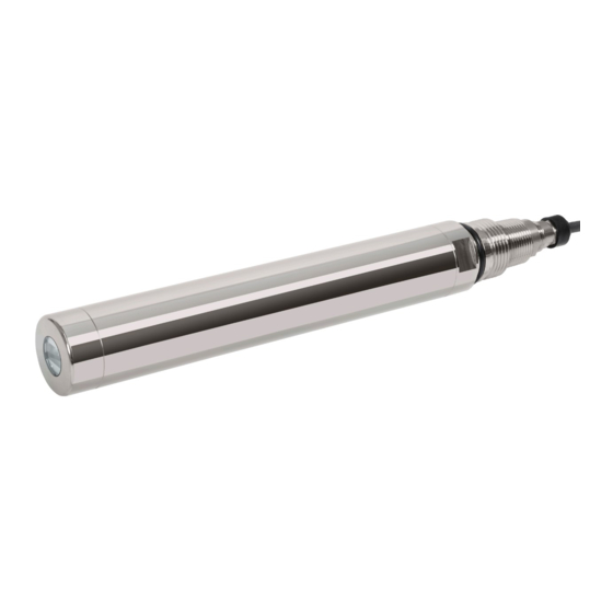
- Page 1 Products Solutions Services BA02165C/07/EN/02.22-00 71572450 2022-05-18 Operating Instructions Memosens CFS51 Sensor for fluorescence measurement...
-
Page 3: Table Of Contents
Memosens CFS51 Table of contents Table of contents 11.4 Disposal ......About this document ....4 Warnings . -
Page 4: About This Document
About this document Memosens CFS51 About this document Warnings Structure of information Meaning This symbol alerts you to a dangerous situation. DANGER Failure to avoid the dangerous situation will result in a fatal or serious Causes (/consequences) injury. If necessary, Consequences of non-compliance (if applicable) ‣... -
Page 5: Basic Safety Instructions
Memosens CFS51 Basic safety instructions Basic safety instructions Requirements for the personnel • Installation, commissioning, operation and maintenance of the measuring system may be carried out only by specially trained technical personnel. • The technical personnel must be authorized by the plant operator to carry out the specified activities. -
Page 6: Operational Safety
Basic safety instructions Memosens CFS51 Operational safety Before commissioning the entire measuring point: 1. Verify that all connections are correct. 2. Ensure that electrical cables and hose connections are undamaged. 3. Do not operate damaged products, and protect them against unintentional operation. -
Page 7: Product Description
Memosens CFS51 Product description Product description Product design The device can be operated directly in the process, without any additional sampling (in- line). The device consists of the following assemblies: • Power supply • Light source • Detectors Detectors detect the measuring signals, digitize them and process them to form a measured value. -
Page 8: Incoming Acceptance And Product
Incoming acceptance and product identification Memosens CFS51 Incoming acceptance and product identification Incoming acceptance 1. Verify that the packaging is undamaged. Notify the supplier of any damage to the packaging. Keep the damaged packaging until the issue has been resolved. -
Page 9: Scope Of Delivery
Memosens CFS51 Incoming acceptance and product identification 4.2.3 Manufacturer address Endress+Hauser Conducta GmbH+Co. KG Dieselstraße 24 D-70839 Gerlingen Scope of delivery The scope of delivery comprises: • Sensor, version as ordered • Operating Instructions Endress+Hauser... -
Page 10: Mounting
Mounting Memosens CFS51 Mounting Mounting requirements 5.1.1 Dimensions NPT 3/4" NPT 3/4" G1" G1" Ø 40 (1.6) Ø 40 (1.6) A0046278 A0048128 2 Dimensions of sensor. Engineering unit: mm 3 Dimensions of sensor with clamping ring. (in) Engineering unit: mm (in) 56 (2.2) - Page 11 Memosens CFS51 Mounting A0046892 5 Dimensions of mounted sensor with assembly. Engineering unit: mm (in) Variable length (depending on mounting) Variable angle (depending on mounting) 36 (1.4) A0047395 6 Dimensions of ring clip with spacer. Engineering unit: mm (in)
- Page 12 Mounting Memosens CFS51 Ø55 (2.2) A0046812 7 Dimensions of solid state reference. Engineering unit: mm (in) 5.1.2 Installation instructions Installation in flow assembly A0048127 8 Installation markings for clamping ring Vertical alignment line for solid state reference Horizontal alignment lines for clamping ring The vertical alignment line on the sensor is used to align the solid state reference.
- Page 13 Memosens CFS51 Mounting A0048146 Optical window Joint of the clamping ring Slide the clamping ring through the sensor from below. 3. Align the joint of the clamping ring perpendicularly to the optical window of the sensor. 4. Slide the clamping ring exactly onto the horizontal alignment lines.
-
Page 14: Mounting The Device
Mounting Memosens CFS51 1. Put the spacer in the desired location. The angle of inclination of the sensor changes. 2. Fix the spacer on the panel → 17. 15° A0046900 A0046899 11 Example with spacer mounted at bottom, 15°... - Page 15 Memosens CFS51 Mounting A0046358 12 Measuring system Transmitter Panel Fixed cable Sensor Ring clip/spacer Assembly Assembly The assembly has the following structure: Endress+Hauser...
- Page 16 Mounting Memosens CFS51 A0046861 13 Flow assembly Hose bracket (anti-bend protection) Spacer Ring clip Hose connection, outlet Flow assembly Hose connection, inlet Connection for cleaning (optional) If possible, the measuring system setup should be free of air bubbles → 13. The assembly offers an integrated bubble trap for assistance.
- Page 17 Memosens CFS51 Mounting 5. Fix the securing plate with the 4 M5 screws in a cross-wise sequence. 5.2.3 Mounting the spacer on the panel The spacer, together with the ring clip, are used to secure the sensor. The spacer must be mounted at the level of the sensor housing.
- Page 18 Mounting Memosens CFS51 Preparatory steps for the sensor without an installed clamping ring: A0048476 Union nut Ring clip Slide the ring clip onto the sensor from below. 2. Slide the union nut onto the sensor from below. A0048477 Clamping ring Alignment lines Slide the clamping ring onto the sensor.
- Page 19 Memosens CFS51 Mounting A0048478 Using the M5 screw, tighten the clamping ring with a torque of 5 Nm. Mounting the sensor with the assembly A0048247 Slide the sensor into the assembly as far as the clamping ring. Endress+Hauser...
- Page 20 Mounting Memosens CFS51 A0048149 Connect the ring clip to the mounted spacer. 3. Use the enclosed M5 screw to fix the ring clip and the spacer. 4. Slide the union nut down as far as the edge of the assembly.
-
Page 21: Post-Mounting Check
Memosens CFS51 Mounting 4. Fit the angle connection, nipple and check valve on the hose connection → 16, 20. 5. Screw on the check valve and tighten by hand. 6. Connect the hose for cleaning. 7. Before commissioning the cleaning, check again to ensure that all connections are firmly seated. -
Page 22: Electrical Connection
Electrical connection Memosens CFS51 Electrical connection WARNING Device is live! Incorrect connection may result in injury or death! ‣ The electrical connection may be performed only by an electrical technician. ‣ The electrical technician must have read and understood these Operating Instructions and must follow the instructions contained therein. -
Page 23: Ensuring The Degree Of Protection
Memosens CFS51 Electrical connection Sample cable (does not necessarily correspond to the original cable supplied) 19 Terminated cable A0045763 A0045764 Outer shield (exposed) 20 Connect the cable to the 21 Press the cable into the Cable cores with ferrules... -
Page 24: Post-Connection Check
Electrical connection Memosens CFS51 Post-connection check Device health and specifications Action ‣ Is the outside of the sensor, assembly or cable free Perform a visual inspection. from damage? Electrical connection Action ‣ Are the mounted cables strain-relieved and not Perform a visual inspection. -
Page 25: Commissioning
Memosens CFS51 Commissioning Commissioning Preliminaries Prior to initial commissioning, ensure that: • The sensor is correctly installed • The electrical connection is correct ‣ Before commissioning, check the chemical material compatibility, the temperature range and the pressure range. 7.1.1 Assembly adjustment The material of the flow assembly used affects the autofluorescence. -
Page 26: Operation
Operation Memosens CFS51 Operation Adapting the measuring device to the process conditions 8.1.1 Turbidity compensation The measured value of the sensor is affected by turbidity that may occur. The device compensates for the turbidity effects automatically and in real-time when turbidity compensation is switched on. - Page 27 Memosens CFS51 Operation The following calibrations are possible: • Calibration • In-situ calibration with the certified solid state reference • Recalibration by the manufacturer • Application adjustment • Calibration or adjustment using reference samples via a value table (1-6 points) •...
- Page 28 Operation Memosens CFS51 CAUTION Medium leaking Risk of injury, damage to clothing and the system! ‣ Make sure that the inlet and outlet of the assembly are shut off. ‣ Make sure that automatic cleaning is switched off before performing the calibration.
- Page 29 Operation 3. If the measurement is still outside the specified limits after multiple rounds of cleaning, send the sensor to your local Endress+Hauser sales organization. Once the process of calibrating with the solid state reference is completed, the following statuses are possible: •...
- Page 30 Operation Memosens CFS51 2-point calibration Measured value deviations are to be compensated for at 2 different points in an application (e.g. the maximum and minimum value of the application). This aims to ensure a maximum level of accuracy between these two extreme values.
- Page 31 Memosens CFS51 Operation 3-point calibration A0039322 26 Principle of multipoint calibration (3 points) Measured value Target sample value Factory calibration Application calibration 1. Select data record. 2. Set 3 different calibration points in the medium and specify the corresponding set points.
- Page 32 Operation Memosens CFS51 f = 1.1 A0039329 27 Principle of factor calibration Measured value Target sample value Factory calibration Factor calibration Offset With the "Offset" function, the measured values are offset by a constant amount (added or subtracted). A0039330 ...
- Page 33 Strong filtering, low sensitivity, slow response to changes (25 seconds) Specialist This menu is designed for the Endress+Hauser Service Department. If the desired signal quality cannot be achieved due to disturbance factors, e.g. air bubbles, we recommend setting the measurement filter to the "Strong" setting.
-
Page 34: Diagnostics And Troubleshooting
Diagnostics and troubleshooting Memosens CFS51 Diagnostics and troubleshooting General troubleshooting When troubleshooting, the entire measuring point must be taken into account: • Transmitter • Electrical connections and cables • Sensor The possible causes of error in the following table refer primarily to the sensor. -
Page 35: Maintenance
Memosens CFS51 Maintenance Maintenance 10.1 Maintenance tasks WARNING UV radiation from this product Can cause damage to the eyes and skin! ‣ Avoid any exposure of the eyes and skin to the unshielded product. ‣ When the sensor is switched on, avoid looking directly into the sensor window without appropriate eye protection. - Page 36 Maintenance Memosens CFS51 3. Slacken the M5 screw that connects the ring clip and the spacer. Make sure that the screw is not lost during removal. 4. Tilt the sensor slightly towards the front. 5. Turn the union nut to release the sensor.
- Page 37 Memosens CFS51 Maintenance 10.1.3 Cleaning the sensor Sensor fouling can affect the measurement results and even cause a malfunction. ‣ To ensure reliable measurements, clean the sensor at regular intervals. The frequency and intensity of the cleaning process depend on the medium.
-
Page 38: Repair
The product must be returned if repairs or a factory calibration are required, or if the wrong product was ordered or delivered. As an ISO-certified company and also due to legal regulations, Endress+Hauser is obliged to follow certain procedures when handling any returned products that have been in contact with medium. -
Page 39: Accessories
Memosens CFS51 Accessories Accessories The following are the most important accessories available at the time this documentation was issued. ‣ For accessories not listed here, please contact your Service or Sales Center. 12.1 Device-specific accessories Flow assembly 71546713 • Material: PVDF V0 •... -
Page 40: Technical Data
Technical data Memosens CFS51 Technical data 13.1 Input Measured variable • PAH concentration in phenanthrene equivalents PAH • Temperature Measuring range 0 to 5 000 µg/l PAH 13.2 Performance characteristics Maximum measured error < 5 % of reading or 6.7 μg/l, at 20 °C (68 °F) according to DIN EN ISO 15839 and MEPC.259(68) and MEPC.340(77) -
Page 41: Process
Memosens CFS51 Technical data Degree of protection • IP 68 • NEMA 6P Electromagnetic Interference emission and interference immunity according to: compatibility (EMC) • EN 61326-1:2013 • EN 61326-2-3:2013 • NAMUR NE21: 2012 13.4 Process Process temperature range –5 to 55 °C (20 to 130 °F) Process pressure range •... -
Page 42: Index
Index Memosens CFS51 Index 0 … 9 1-point calibration ......29 Safety instructions ......5 2-point calibration . - Page 44 *71572450* 71572450 www.addresses.endress.com...