
Related Manuals for Endress+Hauser Flowfit CYA27


Summary of Contents for Endress+Hauser Flowfit CYA27
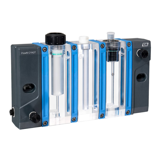
- Page 1 Products Solutions Services BA02059C/07/EN/03.22-00 71559349 2022-03-31 Operating Instructions Flowfit CYA27 Modular flow assembly for multiparameter measurements...
-
Page 3: Table Of Contents
Flowfit CYA27 Table of contents Table of contents About this document ....4 Repair ......56 Warnings . -
Page 4: About This Document
About this document Flowfit CYA27 About this document Warnings Structure of information Meaning This symbol alerts you to a dangerous situation. DANGER Failure to avoid the dangerous situation will result in a fatal or serious Causes (/consequences) injury. If necessary, Consequences of non-compliance (if applicable) ‣... -
Page 5: Basic Safety Instructions
Flowfit CYA27 Basic safety instructions Basic safety instructions Requirements for the personnel • Installation, commissioning, operation and maintenance of the measuring system may be carried out only by specially trained technical personnel. • The technical personnel must be authorized by the plant operator to carry out the specified activities. -
Page 6: Operational Safety
Basic safety instructions Flowfit CYA27 Operational safety Before commissioning the entire measuring point: 1. Verify that all connections are correct. 2. Ensure that electrical cables and hose connections are undamaged. 3. Do not operate damaged products, and protect them against unintentional operation. -
Page 7: Product Description
Product description Product design The Flowfit CYA27 is a modular assembly designed for operating sensors for liquid analysis with a continuous flow of medium. The sensors are placed in specially adapted modules. Due to its modular design, the assembly is flexible in terms of the number, type and position of sensor slots. - Page 8 Product description Flowfit CYA27 Module for disinfection sensors • Medium flows to sensor from below • Sensor slot for 25 mm (0.98 in) sensors • Sensor secured via pressure screw M35x2 • Sensors: → 58 • Flow versions • 5 l/h (1.1 gal/h) •...
- Page 9 Flowfit CYA27 Product description Flow module for continuous flow measurement • Qualitative control and quantitative measurement of the flow volume • Medium flows crosswise from above • Flow versions • 5 l/h (1.1 gal/h) • 30 l/h (6.6 gal/h) • Flow-dependent module whose design varies depending on the selected flow version •...
- Page 10 Product description Flowfit CYA27 Outlet module • With needle valve (outlet valve) • Connection G 1/4' ' (ISO 228-1) • Medium flows crosswise from above • Drill hole for mounting (→ 16) A0043895 Module for particle removal (only available through the replacement and retrofitting module structure XPC0014) •...
-
Page 11: Incoming Acceptance And Product
Flowfit CYA27 Incoming acceptance and product identification Incoming acceptance and product identification Incoming acceptance 1. Verify that the packaging is undamaged. Notify the supplier of any damage to the packaging. Keep the damaged packaging until the issue has been resolved. -
Page 12: Scope Of Delivery
4. Click the product overview. A new window opens. Here you fill information pertaining to your device, including the product documentation. Manufacturer address Endress+Hauser Conducta GmbH+Co. KG Dieselstraße 24 D-70839 Gerlingen Scope of delivery The scope of delivery comprises: •... -
Page 13: Mounting
Flowfit CYA27 Mounting Mounting Mounting requirements 5.1.1 Orientation The assembly is designed for mounting on panels, walls, level surfaces, masts or railings. The only permitted orientation of the assembly is horizontal, → 16. The prescribed orientation of the assembly may limit the installation of certain sensors. - Page 14 Mounting Flowfit CYA27 5.1.3 Dimensions 285 (11.22) 345 (13.58) 225 (8.86) 60 (2.36) 165 (6.50) 165 (6.50) A0045635 1 Dimensions. Engineering unit: mm (in) Disinfection, pH and flow display version with sampling valve, status lighting and flow switch or flow...
- Page 15 Flowfit CYA27 Mounting A0043194 2 Mounting distance. Engineering unit: mm (in) The minimum mounting distance required to remove the sensor(s) is 175 mm (6.9 in). Endress+Hauser...
-
Page 16: Mounting The Assembly
A complete measuring system may contain up to six different sensors and consists, for example, of the following: • Flow assembly Flowfit CYA27 • At least one sensor, e.g CCS51D for the measurement of free chlorine • At least one measuring cable, e.g. CYK10 •... - Page 17 Flowfit CYA27 Mounting Number of modules Spacing between drill 120 (4.73) 180 (7.09) 240 (9.45) holes mm (in) The mounting materials required to secure the device to the wall are not included in the scope of delivery. 1. Provide the mounting materials to secure the device to the wall (screws, wall plugs) onsite.
- Page 18 Mounting Flowfit CYA27 A0043207 A0043208 6 2 securing clips for 1 to 5 modules 7 3 securing clips for 6 modules With six modules, three securing clips are required for increased stability. 1. Position the assembly in the center of the wall holder.
-
Page 19: Mounting Assembly In The Process
Flowfit CYA27 Mounting Mounting assembly in the process 5.3.1 General installation instructions CAUTION Risk of injury from high pressure, high temperature or chemical hazards if process medium escapes. ‣ Wear protective gloves, protective goggles and protective clothing. ‣ Install the assembly only in vessels or pipes that have cooled down, are empty and unpressurized and have been rinsed. - Page 20 Pressure-reducing valve (optional, not included in the scope of delivery) Filter trap (optional, not included in the scope of delivery) Assembly Flowfit CYA27 Manual valve (optional in the case of an upward-sloping output line, not included in the scope of delivery)
- Page 21 Check valve (not included in the scope of delivery) Pressure-reducing valve (optional, not included in the scope of delivery) Filter trap (optional, not included in the scope of delivery) Assembly Flowfit CYA27 Manual valve (not included in the scope of delivery) Main output line...
- Page 22 Mounting Flowfit CYA27 5.3.5 Dosing (optional) For the metered addition of a cleaning agent or an acid (to acidify the medium), the following is required at a minimum: • an assembly with dosing module, • a feeder tank for the liquid to be dosed (must be provided by the customer) and •...
- Page 23 Flowfit CYA27 Mounting WARNING Escaping cleaning solution If cleaning solution escapes, there is a risk of injury from high pressure, high temperature or chemical hazards! ‣ Adhere to the maintenance intervals for the components used, such as pipes or a dosing pump, and replace the component in the event of a defect.
- Page 24 Mounting Flowfit CYA27 A0047952 Main pipe Branch pipe Valve (optional, not included in the scope of delivery) Check valve (optional, not included in the scope of delivery) Pressure-reducing valve (optional, not included in the scope of delivery) Media inlet of the assembly...
-
Page 25: Connecting The Flow Switch, Flow Measurement Or Status Lighting (Optional)
Flowfit CYA27 Mounting Connecting the flow switch, flow measurement or status lighting (optional) WARNING Device is live! Incorrect connection may result in injury or death! ‣ The electrical connection may only be established by an electrical technician. ‣ The electrical technician must have read and understood the instructions in this manual and must adhere to them. - Page 26 Mounting Flowfit CYA27 4. Wire the cables in accordance with the wiring diagram. The cables for the flow switch and flowmeter and the status lighting cable are identical in design. Plug-in terminals on the CM44x ‣ ‣ ‣ Press the screwdriver against...
- Page 27 Flowfit CYA27 Mounting – – – – – – A0047955 BASE-E or BASE2-E module DIO module (included in the scope of delivery for the CM44x transmitter or order separately) Flow switch cable Flow switch Distributor terminal block (is located in the CM44x transmitter as standard)
- Page 28 Mounting Flowfit CYA27 3. Assign a limit switch to the binary input in: Menu/Setup/Basic setup/Limit switch x with the options Data source: Binary input x:1, Input variable: Level, Cleaning program: ---, Operating mode: Above limit, Function: On, Switch-on delay: 0 s,...
- Page 29 Flowfit CYA27 Mounting 4. Assign a limit switch to the binary input if you are configuring the detection of a flow volume that is outside the specified range: Go to Menu/Setup/Basic setup/Limit switch x and configure the options Data source: Binary input x:1, Input variable: Flow, Cleaning program: ---, Operating...
- Page 30 Mounting Flowfit CYA27 A0048018 BASE-E or BASE2-E module DIO module (included in the scope of delivery for the CM44x transmitter or order separately) Status lighting cable Status lighting Distributor terminal block (is located in the CM44x transmitter as standard) Status lighting cable...
- Page 31 Flowfit CYA27 Mounting 2. Make the following settings Function: Device status signal, Operating mode: NAMUR S + NAMUR C + NAMUR F When the alarm relay is used, it is no longer available for other messages. 3. Option B, relay module (2R, 4R, AOR module) Open Menu/Setup/Outputs/Relay y:x.
- Page 32 Mounting Flowfit CYA27 A0048025 BASE-E or BASE2-E module DIO module (included in the scope of delivery for the CM44x transmitter or order separately) Status lighting cable Status lighting Status lighting cable Connection Brown (BN) BASE-2-E module, alarm, terminal 41 White (WH)
- Page 33 Flowfit CYA27 Mounting 2. Make the following settings Function: Diagnostic message, Operating mode: NAMUR F When the alarm relay is used, it is no longer available for other messages. 3. Option B, relay module (2R, 4R, AOR module) Open Menu/Setup/Outputs/Relay y:x.
- Page 34 Mounting Flowfit CYA27 A0048032 BASE-E or BASE2-E module DIO module (included in the scope of delivery for the CM44x transmitter or order separately) Status lighting cable Status lighting Flow switch cable Flow switch Distributor terminal block 2 (is located in the CM44x transmitter as standard)
- Page 35 Flowfit CYA27 Mounting Distributor terminal block cable 1 Terminal Connection Connecting cable, green (GN) DIO module, power connection, port 1, terminal 48 Connecting cable, green (GN) DIO module, digital in, port 1, terminal 92 Distributor terminal block cable 2 Terminal...
- Page 36 Mounting Flowfit CYA27 Activating the connected binary output 1. Go to Setup/Outputs/ Binary output y:x and enable Binary output. 2. Set Signal type: Static signal, Function: Device status signal, Operating mode: OK, NAMUR F. If a relay of a 2R or 4R or AOR module is used instead of the alarm relay, the wiring and the software configuration are the same apart from the location and name of the relay.
- Page 37 Flowfit CYA27 Mounting Assigning diagnostic message S910 of the limit switch as an error message F for insufficient flow 1. Reconfigure the diagnostic message for the limit switch (S910) in Menu/Setup/ Basic setup/Diagnostic settings/Diagnostic behavior/S910 limit switch. The status of the limit switch and thus the flow rate in the assembly is available as a process value for all outputs of the transmitter.
-
Page 38: Installing Sensor In Assembly
2. The assembly is supplied to the customer with a dummy plug inserted in the assembly: remove dummy plug and O-ring (1) from the assembly. 3. Slide the sensor with the adapter for Flowfit CYA27 into the opening of the assembly. 4. Screw the union nut onto assembly on block. - Page 39 Flowfit CYA27 Mounting 5.5.2 pH, ORP or oxygen sensor A0043537 Dummy screw, thrust collar and O-ring 1. The assembly is supplied to the customer with a dummy screw mounted in the assembly. 2. Remove dummy screw, thrust collar and O-ring (1) from the assembly using a hexagon wrench AF17.
-
Page 40: Connecting Optional Accessories
Mounting Flowfit CYA27 5.5.3 Conductivity sensor A0043538 Dummy screw, thrust collar and O-ring 1. The assembly is supplied to the customer with a dummy screw mounted in the assembly. 2. Remove dummy screw, thrust collar and O-ring (1) from the assembly using a hexagon wrench AF17. -
Page 41: Post-Mounting Check
Flowfit CYA27 Mounting Option Process adapter Hose fitting OD 6 mm (0.24 in), ID 4 mm (0.16 in) A0043720 Hose fitting OD 8 mm (0.31 in), ID 6 mm (0.24 in) A0043719 Adapter for potential equalization connection G 1/4 A0043718... -
Page 42: Commissioning
Commissioning Flowfit CYA27 Commissioning CAUTION Risk of injury from high pressure, high temperature or chemical hazards if process medium escapes. ‣ Before subjecting the assembly to the process pressure, verify that all connections are sealed. ‣ Wear personal protective equipment consisting of protective gloves, goggles and protective clothing. - Page 43 Flowfit CYA27 Commissioning 6.2.2 Switch-on sequence (with particle separator) 1. Open the valve at the outlet. The valve should only be closed when removing sensors in order to prevent medium backflow. 2. Open the valve at the inlet slightly. 3. Set the flow via the valve at the top of the particle separator.
-
Page 44: Operation
Operation Flowfit CYA27 Operation CAUTION Compressed media Risk of injury from high pressure, high temperature or chemical hazards if process medium escapes. ‣ Wear personal protective equipment consisting of protective gloves, goggles and protective clothing. Adapting the measuring device to the process conditions 7.1.1... -
Page 45: Sampling
Flowfit CYA27 Operation Sampling Depending on the module selected, the assembly can be optionally fitted with a valve for sampling. The sample, for example for a DPD test for sensor calibration, is taken as follows: 1. Carefully open the sampling valve and rinse for a few seconds. - Page 46 Operation Flowfit CYA27 To avoid this, the sensor values at the transmitter can be set to HOLD for the duration of sampling. In this case, sampling is performed as follows: 1. Set the sensor measured values on the transmitter to HOLD.
-
Page 47: Diagnostics And Troubleshooting
Flowfit CYA27 Diagnostics and troubleshooting Diagnostics and troubleshooting General troubleshooting Faults at the measuring point can affect not only the assembly but also the sensors and transmitters used. For this reason, the respective Operating Instructions of the sensors and transmitters must also be observed for diagnostics and troubleshooting. -
Page 48: Maintenance
Maintenance Flowfit CYA27 Maintenance CAUTION Danger resulting from improper maintenance ‣ Maintenance work on the assembly that compromises pressure safety must be performed only by authorized specialist staff. ‣ The valve must comply with the original technical specifications following each maintenance activity. -
Page 49: Maintenance Tasks
Flowfit CYA27 Maintenance Maintenance tasks 9.2.1 Taking out of service CAUTION Compressed media Risk of injury from high pressure, high temperature or chemical hazards if process medium escapes. ‣ Wear personal protective equipment consisting of protective gloves, goggles and protective clothing. - Page 50 Maintenance Flowfit CYA27 1. Open the sampling valve. 2. Open the sensor slot or the outlet connection, whichever is positioned further away from the valve. The process medium drains off through the sampling valve. 3. Collect process medium at the sampling valve.
- Page 51 Flowfit CYA27 Maintenance 2. Open the inlet and outlet valves. 3. Rinse the assembly. 4. Collect the escaping liquid. 9.2.4 Cleaning the assembly and sensors Clean the assembly and sensor regularly as required. The frequency and intensity of cleaning depend on the medium. Cleaning of the surfaces of the assembly and sensors in contact with the medium can be performed manually or automatically (→...
- Page 52 Maintenance Flowfit CYA27 Manual cleaning For manual cleaning of the assembly, proceed as follows: 1. Take the measuring point out of operation (→ 49). 2. Rinse and drain the assembly as required. 3. Remove the sensors. 4. Clean the assembly.
- Page 53 Flowfit CYA27 Maintenance 6. Put the measuring point into operation (→ 42), paying particular attention to leak-tightness. The needle valves at the inlet and outlet can only be dismantled if the assembly with additional valves is integrated into the process.
-
Page 54: Disassembly (E.g. For Modification Or Cleaning)
Maintenance Flowfit CYA27 The correct selection of the seal depends on the flow direction of the adjacent modules in each case. The flow direction is indicated by an arrow. • The gasket seal with bore hole should be used if the arrows of the adjacent module halves are at the same height in each case (→... - Page 55 Flowfit CYA27 Maintenance A0043717 Detents 1. Keep detents pressed down. 2. Slide the assembly upwards and out of the holder. Endress+Hauser...
-
Page 56: Repair
Repair Flowfit CYA27 Repair CAUTION Incorrect repair Danger due to damage to the device! ‣ Any damage to the assembly that compromises pressure safety must be repaired only by authorized and qualified personnel. ‣ The assembly must comply with the original technical specifications following repair work. -
Page 57: Return
The product must be returned if repairs or a factory calibration are required, or if the wrong product was ordered or delivered. As an ISO-certified company and also due to legal regulations, Endress+Hauser is obliged to follow certain procedures when handling any returned products that have been in contact with medium. -
Page 58: Accessories
Accessories Flowfit CYA27 Accessories The following are the most important accessories available at the time this documentation was issued. ‣ For accessories not listed here, please contact your Service or Sales Center. 11.1 Device-specific accessories 11.1.1 Disinfection sensors CCS51 / Memosens CCS51D •... - Page 59 Flowfit CYA27 Accessories Memosens CPS41E • pH sensor for process technology • With ceramic junction and KCl liquid electrolyte • Digital with Memosens 2.0 technology • Product Configurator on the product page: www.endress.com/cps41e Technical Information TI01495C 11.1.3 ORP sensors Memosens CPS12E •...
-
Page 60: Technical Data
Technical data Flowfit CYA27 Technical data 12.1 Power supply Cable specification Cable accessories 10 m (32.8 ft), M12 socket straight, 5-pin version Cable accessories Ex (US) Cl.1 Div.2 cable, 10 m (32.8 ft), M12 socket straight, 4-pin version 12.2 Performance characteristics Reference operating 20 °C (68 °F) -
Page 61: Process
Flowfit CYA27 Technical data 12.4 Process Process temperature range 0 to 60 °C (32 to 140 °F), non-freezing Process pressure range 0 to 4 bar (0 to 58 psi) relative Pressure/temperature p [psi] p [bar] ratings 70 T[°C] T[°F] A0044367 ... -
Page 62: Mechanical Construction
Technical data Flowfit CYA27 12.5 Mechanical construction → 14 Weight Number of modules Weight in kg (lb) 0.9 kg 1.5 kg 2.1 kg 2.7 kg 3.3 kg 3.8 kg (1.98 lb) (3.31 lb) (4.63 lb) (5.95 lb) (7.28 lb) (8.38 lb) - Page 63 Flowfit CYA27 Technical data Turck, BI8-M18-AP6X-H1141/S1751 Area of application Hazardous area CSA Cl. I Div.2 Switching element function NAMUR NC contact Switching element Inductive principle Enclosure material Brass, chrome-plated Flow measurement BIO-TECH, FCH-m--PVDF Area of application Non-hazardous area Measuring principle...
-
Page 64: Index
Index Flowfit CYA27 Index Accessories ....... . 58 Technical data ......60 Troubleshooting . - Page 68 *71559349* 71559349 www.addresses.endress.com...