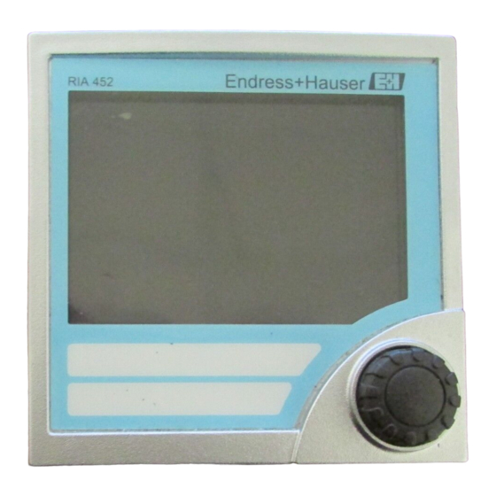
Endress+Hauser RIA452 Operating Instructions Manual
Process indicator with pump control
Hide thumbs
Also See for RIA452:
- Operating instructions manual (236 pages) ,
- Brief operating instructions (60 pages) ,
- Technical information (15 pages)

Related Manuals for Endress+Hauser RIA452


Summary of Contents for Endress+Hauser RIA452
- Page 1 Products Solutions Services BA00265R/09/EN/16.21 71517687 2021-02-20 Valid from version 02.01.xx (device software) Operating Instructions RIA452 Process indicator with pump control...
-
Page 3: Table Of Contents
RIA452 Table of contents Table of contents About this document ....4 Disposal ......48 Document conventions . -
Page 4: About This Document
About this document RIA452 About this document Document conventions 1.1.1 Safety symbols DANGER This symbol alerts you to a dangerous situation. Failure to avoid this situation will result in serious or fatal injury. WARNING This symbol alerts you to a dangerous situation. Failure to avoid this situation can result in serious or fatal injury. - Page 5 A, B, C, ... Views A-A, B-B, C-C, ... Sections Hazardous area Safe area (non-hazardous area) 1.1.5 Registered trademarks HART® Registered trademark of the HART Communication Foundation, Austin, USA Applicator®, FieldCare®, Field Xpert™, HistoROM® Registered or registration-pending trademarks of the Endress+Hauser Group Endress+Hauser...
-
Page 6: Safety Instructions
Safety instructions RIA452 Safety instructions Requirements for the personnel The personnel for installation, commissioning, diagnostics and maintenance must fulfill the following requirements: ‣ Trained, qualified specialists must have a relevant qualification for this specific function and task. ‣ Are authorized by the plant owner/operator. -
Page 7: Product Safety
RIA452 Safety instructions Product safety This measuring device is designed in accordance with good engineering practice to meet state-of-the-art safety requirements, has been tested, and left the factory in a condition in which it is safe to operate. It meets general safety standards and legal requirements. It also complies with the EC directives listed in the device-specific EC Declaration of Conformity. -
Page 8: Incoming Acceptance And Product
Power Name and address of manufacturer 3.1.2 Name and address of manufacturer Name of manufacturer: Endress+Hauser Wetzer GmbH + Co. KG Address of manufacturer: Obere Wank 1, D-87484 Nesselwang or www.endress.com Scope of delivery The scope of delivery of the process indicator comprises: •... -
Page 9: Installation
RIA452 Installation Installation Installation conditions The permitted ambient conditions must be observed during installation and operation (see the "Technical data" section of the Operating Instructions). The device must be protected from exposure to heat. 4.1.1 Installation dimensions Required panel cutout 92 mm (3.62 in)x92 mm (3.62 in). Ensure an installation depth of 150 mm (5.91 in) for the device plus cable. -
Page 10: Electrical Connection
Electrical connection RIA452 4. Remove the protective foil from the display. Electrical connection A0031253 3 Terminal assignment of process indicator. Internal circuits illustrated as dotted lines. Current input, terminals 12 and 82 jumpered Digital output, passive open collector, max. 28 V, internally. -
Page 11: Universal Input Option
RIA452 Electrical connection Terminal Terminal assignment Description Signal ground (current) 24 V sensor power supply 1 Transmitter power supply (intrinsically safe if required) Ground, sensor power supply 1 Normally closed (NC) Relay 1 Common (COM) Normally open (NO) Normally closed (NC) -
Page 12: Connecting The Process Indicator
Electrical connection RIA452 A0031256 4 Universal input terminal assignment Current input 0/4 to 20 mA Thermocouples Voltage input ±1 V RTD assembly, 4-wire Voltage input ±30 V RTD assembly, 3-wire Terminal Terminal assignment +0/4 to 20 mA signal Signal ground (current, voltage, temperature) - Page 13 RIA452 Electrical connection 20...36 VDC 20...28 VAC 50/60 Hz 90..250 VAC 50/60 Hz N/L- L/L+ A0031259 5 Power supply connection 5.2.2 Connecting the external sensors Active and passive sensors with analog, TC, resistance and RTD sensors can be connected to the device.
-
Page 14: Post-Connection Check
7 Connection of 2-wire sensor in the hazardous area to current input 0/4 to 20 mA Passive sensor, 2-wire RB223 Ex passive barrier RIA452 process indicator (terminal 12 and 82 jumpered internally) Universal input A0031273 8 Connection of 4-wire sensor, transmitter power supply and universal input... - Page 15 RIA452 Electrical connection Electrical connection Notes Are the mounted cables strain-relieved? Are the power supply and signal cables connected correctly? See wiring diagram on the housing Are all of the screw terminals well-tightened? Endress+Hauser...
-
Page 16: Operation Options
Operation options RIA452 Operation options Overview of operation options 6.1.1 Display and operating elements Remove the protective film from the display as this would otherwise affect the readability of the display. A0031274 9 Display and operating elements Operational indicator, green, is lit when supply voltage is applied Fault indicator, red, flashes in the event of a sensor or device error Limit indicator: the symbol is displayed if a relay is energized. -
Page 17: Structure And Function Of The Operating Menu
RIA452 Operation options Relay indicator • Relay not energized: nothing indicated • Relay energized: (symbol is lit) Status display for digital inputs • Digital input configured: (green) • Signal at digital input: (yellow) Structure and function of the operating menu... -
Page 18: Access To The Operating Menu Via The Local Display
Operation options RIA452 Dimension Dec. point T Set count A Set count B Totalizer Reset totalizer Flow calculation Dimension input Dimension of Decimal point for signal linearized value formula Reset total Calc flow Dim. Input Dim. flow Dec. flow Decimal point for... - Page 19 RIA452 Operation options 6.3.1 Operation via the jog/shuttle dial A) 3-key function • Press = "Enter" • Turn clockwise = "+" • Turn counterclockwise = "-" A0031352 10 Operation via jog/shuttle dial B) List selection ▾ Arrow points down: Selection is at the start of the picklist.
- Page 20 Operation options RIA452 6. Set/change all the characters in this way. Once you have set the last character, press the jog/shuttle dial briefly. The entry is accepted. 7. Alternatively, press and hold the jog/shuttle dial at any point for longer than 1 s and then release.
-
Page 21: Commissioning
RIA452 Commissioning Commissioning Function check Make sure that all post-connection checks have been carried out before you commission your device: Checklist connection check → 14 Remove the protective strip from the display as this restricts display legibility otherwise. Switching on the measuring device Once the operating voltage is applied, the green LED indicates that the device is operational. - Page 22 Commissioning RIA452 7.3.1 Analog input - INPUT/M1 The Analog input menu, displayed as INPUT in the device, contains all the parameters that can be selected for the input. Function (menu Parameter setting Description item) Signal type 4 - 20 mA...
- Page 23 RIA452 Commissioning Function (menu Parameter setting Description item) 100% value -99999 to 99999 End value of measured value, can be selected for 100.0 analog signal types. Offset -99999 to 99999 Shifts the zero point of the response curve. This function is used to adjust the sensor.
- Page 24 Commissioning RIA452 Function (menu Parameter setting Description item) Dec. point XXXXX Number of decimal places for bar graph scaling. XXXX.X XXX.XX XX.XXX X.XXXX Bar 0% -99999 to 99999 Start value for the bar graph Bar 100% -99999 to 99999 End value for the bar graph 100.0...
- Page 25 RIA452 Commissioning Function (menu Parameter setting Description item) Simu mA Simulates the current output and outputs the selected 0.0 mA current at the output, irrespective of the input value. 3.6 mA Is automatically switched "OFF" when the "Simu mA" 4 mA menu item is exited.
- Page 26 Commissioning RIA452 • Fault monitoring: Sampl. Time = 0 In the case of fault monitoring, the level at the digital input is changed by a fault at the pump. • Startup monitoring: Sampl. Time > 0 In the case of startup monitoring, correct start-up of the pump is reported back to the process indicator via a level change at the digital input.
- Page 27 RIA452 Commissioning Rela 1 Rela 2 Alarm relay Error message Events A0032766-EN 15 Startup monitoring operating mode Event 1 shows trouble-free operation of pump 1. Pump 1 is activated by a demand signal due to a limit value violation. The status signal at DI1, which changes within T, indicates that the pump is operating correctly, pump 1 continues pumping.
- Page 28 Commissioning RIA452 Function (menu Parameter setting Description item) Ref. num. Input Use this function to select which value is used: Lin. table • Input: scaled value from analog input • Lin. table: value from linearization table or current flow for calculation of channel...
- Page 29 RIA452 Commissioning Min operating mode A0032767 16 Min operating mode Measured value Time Threshold+hysteresis Threshold Relay Hysteresis The following parameters must be configured: Menu Function (menu item) Setting value LIMIT 1 to 8/M10 to 17 Function Setpoint A Value for switching threshold...
- Page 30 Commissioning RIA452 The following parameters must be configured: Menu Function (menu item) Setting value LIMIT 1 to 8/M10 to 17 Function Setpoint A Value for switching threshold Hysteresis Value for hysteresis Grad operating mode A0032769 18 Grad operating mode...
- Page 31 RIA452 Commissioning Alarm operating mode A relay with the "Alarm" operating mode is activated if the following events occur: • Analog input (4 to 20 mA) < 3.6 mA (lower Namur limit) or > 21.0 mA (upper Namur limit) • HW error EEPROM (E101) The relay remains energized even after acknowledgment.
- Page 32 Commissioning RIA452 Alternate A0032771 20 Alternating pump control With alternating pump control Without alternating pump control Measured value Setpoint A2 Relay 3 switching state Time Setpoint A2 - hysteresis 2 Relay 2 switching state Setpoint A3 Setpoint A1 Relay 1 switching state...
- Page 33 RIA452 Commissioning The following parameters must be configured for the example above: Menu Function (menu item) Setting value LIMIT 1 to 3/M10 to 12 In each case: setpoint A Value for switching threshold In each case: hysteresis Value for hysteresis...
- Page 34 Commissioning RIA452 This function can only be selected if the "Pulse output" option is available in the device. Function Parameter setting Description (menu item) Ref. integr. Input Use this function to select which value should be integrated. Lintab • Input = measured value •...
- Page 35 RIA452 Commissioning Function Parameter setting Description (menu item) Dim. flow m3/s, l/s, hl/s, igal/s, Dimension of linearized value 1 hl = 100 l usgal/s, barrels/s, 1 m³ = 1 000 l • l = liter inch3/s, ft3/s, Usmgal/s, 1 Ml = 1 000 000 l •...
- Page 36 Commissioning RIA452 Function Parameter setting Description (menu item) QV 316 QV 316 = Khafagi-Venturi flume QV 316 ISO Venturi ISO Venturi flumes 415 = ISO Venturi flume 415 425 = ISO Venturi flume 425 430 = ISO Venturi flume 430...
- Page 37 RIA452 Commissioning Function Parameter setting Description (menu item) Rect.WThr Rectangular weir with constriction 2H = rectangular weir with constriction 2H 3H = rectangular weir with constriction 3H 4H = rectangular weir with constriction 4H 5H = rectangular weir with constriction 5H...
- Page 38 Commissioning RIA452 Calculation formula for flow measurement If you have selected "Formula" under "Calc. flow" for flow measurement, the flow is calculated using the following formula: Q = C * (h α + γ*h β Where: • Q: flow in m³/h •...
- Page 39 RIA452 Commissioning Power on Digital input 1 Limit value B Relay 2 Counter run time Limit value A Relay 1 Restart counter Restart counter When the preset counter is activated, limit values 1 and 2 are permanently assigned to the preset counter function (output 1 = main switchoff, output 2 = preliminary switchoff).
- Page 40 Commissioning RIA452 7.3.8 Min/Max memory - MIN MAX/M20 The process indicator can save a minimum and a maximum measured value. The input signal or the signal processed using the linearization table are available as the signal source. The memories are reset manually or using the digital input (→ 25).
- Page 41 RIA452 Commissioning Tank linearization 1500 m³ 100% 0 m³ 0% 10% 20% 30% 100% A0032774 23 Example of tank linearization You want to determine the amount of grain filled into a silo, display this information on site and transmit it to a process control system. A 4 to 20 mA level sensor determines the level in the vessel, the relationship between the level (m) and volume (m³) is known and...
- Page 42 Commissioning RIA452 Menu Function (menu item) Setting value ANALOG OUT / M 3 Ref. num Output value (Lintab) Out range Signal type (0-20 mA) Fail mode Failure mode (const) Fail value Value in event of error (21.0 mA) DISPLAY / M 2 Ref.
- Page 43 RIA452 Commissioning Function (menu Parameter setting Description item) Rel. mode Switching behavior of the relays. • Off = relays are de-energized in the event of a limit value violation • On = relays are energized in the event of a limit value violation Grad.
-
Page 44: Maintenance
Various accessories, which can be ordered with the device or subsequently from Endress +Hauser, are available for the device. Detailed information on the order code in question is available from your local Endress+Hauser sales center or on the product page of the Endress+Hauser website: www.endress.com. -
Page 45: Troubleshooting
RIA452 Troubleshooting Troubleshooting 10.1 Troubleshooting instructions NOTICE Explosion hazard from open device in Ex environment ‣ In the case of Ex-devices, error diagnosis cannot be performed on an open device as this invalidates the type of protection. Display Cause Solution... - Page 46 Troubleshooting RIA452 Error code Cause Effect Solution E223 Pump failure Digital input 3 E224 Pump failure Digital input 4 E290 Number overshoot due to Decimal point position cannot Check decimal point position decimal point shift be changed and number range The errors listed above can be evaluated with a relay in the "Alarm"...
- Page 47 50078843 Terminal (relay 1-8) 6-pin 51005104 Terminal (analog input) 4-pin 51009302 Terminal (analog output, open collector, transmitter power supply) 6- 51008588 Terminal (digital inputs) 5-pin 51008587 Jumper operating lock 50033350 W/O. No. Casing fastening clip RIA452 (1 pc) 71035359 Endress+Hauser...
-
Page 48: Return
Return RIA452 Return The requirements for safe device return can vary depending on the device type and national legislation. 1. Refer to the website for more information: http://www.endress.com/support/return-material 2. Return the device if repairs or a factory calibration are required, or if the wrong device was ordered or delivered. -
Page 49: Technical Data
RIA452 Technical data Technical data 13.1 Input 13.1.1 Measured variable • Current (standard) • Digital inputs (standard) • Current/voltage, resistance, RTD assembly, thermocouples (universal input option) 13.1.2 Measuring range Current input: Current: • 0/4 to 20 mA +10% overrange, 0 to 5 mA •... -
Page 50: Output
Technical data RIA452 13.2 Output 13.2.1 Output signal • Relay, transmitter power supply (standard) • Current, voltage, pulse, intrinsically safe transmitter power supply (option) 13.2.2 Signal on alarm No measured value visible on the LC display, no background illumination, no sensor power supply, no output signals, relays behave in safety-oriented manner. - Page 51 RIA452 Technical data Electrical specifications: • Relay type: changeover • Relay switching capacity: 250 V / 30 V , 3 A • Switch cycles: typically 10 • Switching frequency: max. 5 Hz • Minimum switching load: 10 mA / 5 V...
-
Page 52: Power Supply
Technical data RIA452 13.3 Power supply 13.3.1 Terminal assignment 20..36V DC 20...28V AC 50/60Hz 90...250V AC 50/60Hz RS232 A0028439 26 Terminal assignment of process indicator Current input (12 and 82 jumpered internally) Transmitter power supply and analog output - passive sensor... - Page 53 RIA452 Technical data Universal input option A0028457 27 Universal input terminal assignment Current input 0/4 to 20 mA Thermocouples Voltage input ±1 V RTD assembly, 4-wire Voltage input ±30 V RTD assembly, 3-wire Interface connection data RS232 • Connection: jack socket 3.5 mm, rear of device •...
-
Page 54: Performance Characteristics
Technical data RIA452 13.4 Performance characteristics 13.4.1 Reference operating conditions Power supply: 230 V ±10%, 50 Hz ±0.5 Hz Warm-up period: 90 min Ambient temperature: 25 °C (77 °F) 13.4.2 Maximum measured error Current input Accuracy 0.1% of full scale... -
Page 55: Installation
RIA452 Technical data Input: Range: Maximum measured error of measuring range (oMR): Typ U (Cu-CuNi), ± (0.15% oMR + 0.5 K (0.9 °F)) from –200 to 600 °C (–328 to 1 112 °F) (DIN43710) –100 °C (–148 °F) Typ S (Pt10Rh-Pt), 0 to 1 768 °C (32 to 3 214 °F) ±... -
Page 56: Mechanical Construction
Technical data RIA452 13.6.4 Climate class To IEC 60654-1, Class B2 13.6.5 Degree of protection Front IP 65 / NEMA 4 Device casing IP 20 13.6.6 Shock and vibration resistance 2 Hz (+3/-0) ... 13.2 Hz: ±1 mm (±0.04 in) 13.2 to 100 Hz: 0.7 g... - Page 57 RIA452 Technical data +0.8 +0.03 (3.62 A0028476 29 Panel cutout, dimensions in mm (in) 13.7.2 Weight 500 g (17.64 oz) 13.7.3 Materials • Housing front: ABS plastic • Housing casing: ABS GF plastic 13.7.4 Terminals Plug-in screw terminals, clamping range 1.5 mm...
-
Page 58: Operability
Technical data RIA452 13.8 Operability 13.8.1 Local operation Display elements A0028477 30 Display elements of the process indicator Device status LEDs: green - device ready for operation; red - device or sensor malfunction Bar graph with overrange and underrange... -
Page 59: Certificates And Approvals
13.9.2 Ex approval Information about currently available Ex versions (ATEX, FM, CSA. etc.) can be supplied by your Endress+Hauser sales organization on request. All explosion protection data are given in a separate documentation which is available upon request. 13.9.3 Other standards and guidelines The manufacturer confirms compliance with all the relevant external standards and guidelines. -
Page 60: Appendix
Appendix RIA452 Appendix 14.1 Flow conversion Conversion of various units to m³/h Liter US megagallon • 1 l/s = 3.6 m • 1 USMgal/s = 13 627 481.6155 m • 1 l/min = 0.06 m • 1 USMgal/min = 2 271 246 936 m •... -
Page 61: Index
RIA452 Index Index 0 … 9 Menu ANALOG OUT ......24 24-hour activation function ....33 DIGITAL INP. - Page 64 *71517687* 71517687 www.addresses.endress.com...