Endress+Hauser ria45 Operating Instructions Manual
Process meter with control unit
Hide thumbs
Also See for ria45:
- Operating instructions manual (80 pages) ,
- Brief operating instructions (44 pages) ,
- Brief operating instructions (40 pages)

Related Manuals for Endress+Hauser ria45


Summary of Contents for Endress+Hauser ria45
-
Page 1: Operating Instructions
Products Solutions Services BA00272R/09/EN/04.14 71251379 SW Version 1.03.xx Operating Instructions RIA45 Panel meter... - Page 2 (I, U, R, TC, RTD) 1 x Digital (OC) Power supply: Loop power supply 24 to 230 V AC/DC (-20%/+10%) intrinsically safe Relays: Interfaces: 2 x relays (limits) 1 x PC interface optional a0010175-en Fig. 1: Block circuit diagram Endress+Hauser...
-
Page 3: Table Of Contents
RIA45 Table of contents Safety instructions ....4 Technical data ....42 Designated use . -
Page 4: Safety Instructions
Safety instructions RIA45 Safety instructions Safe operation of the device is only guaranteed if these Operating Instructions have been read and the safety instructions they contain have been observed. Designated use The device evaluates analog process variables and shows them on its multicolored display. -
Page 5: Notes On Safety Conventions And Icons
RIA45 Safety instructions Notes on safety conventions and icons Always refer to the safety instructions in these Operating Instructions labelled with the following symbols: Symbol Meaning WARNING! This symbol alerts you to a dangerous situation. Failure to avoid this situation can result in serious or fatal injury. -
Page 6: Identification
Identification RIA45 Identification Device designation 2.1.1 Nameplate Compare the nameplate on the device with the following diagram: a0010405 Fig. 2: Nameplate of the device (sample): Order code, serial number and ID number of the device Power supply Power consumption Approval... -
Page 7: Installation
RIA45 Installation Installation Incoming acceptance, transport, storage The permitted ambient and storage conditions must be observed. The precise specifications can be found in Section 10 "Technical data". 3.1.1 Incoming acceptance On receipt of the goods, check the following points: • Are the packaging or contents damaged? •... -
Page 8: Installation Procedure
Installation RIA45 Installation procedure The panel cutout required measures 92x45 mm (3.62x1.77 inches). a0010404 Fig. 3: Installation in the panel Screw the threaded rods (pos. 1) into the positions provided on the mounting frame (pos. 2). Four opposing screw positions (pos. 3/4) are available for this purpose. -
Page 9: Wiring
RIA45 Wiring Wiring WARNING Danger through electric tension ‣ Make sure that no voltage is supplied when wiring the device. ‣ The protective ground connection must be established before any other connection is made. A source of danger could arise if the protective ground connection is disconnected. - Page 10 Wiring RIA45 Overview of possible connection options at the device Terminal assignment of analog inputs, channel 1 and 2 (optional) a0010406 Connection of the loop power supply 2-wire 4-wire a0010407 a0010408 Connection of the analog input RTD/Resistance 2-wire RTD/Resistance 3-wire...
-
Page 11: Post-Connection Check
RIA45 Wiring Connection of the power supply 24 to 230 V AC/DC (-20 % / +10 %) 50/60 Hz a0010418 Interface for configuring with the FieldCare PC software a0010417 NOTICE High-energy transients can damage the device ‣ For long signal lines fit a suitable surge arrester upstream. -
Page 12: Operating Elements And Display
Firstly, install the device driver "CDI DTMlibrary" in FieldCare. It can be found under "Endress+Hauser Device DTMs → Service / Specific → CDI" in FieldCare. Then the DTM catalog must be updated. Add the new installed DTMs to the DTM catalog. - Page 13 RIA45 Operating elements and display In the installation assistent, do not carry out the automatic search for a driver. For this, choose "No, not this time" and click "Next". In the subsequent window, choose "Install from a list or specific location" and click "Next".
-
Page 14: Display And Device Status Indicator/Led
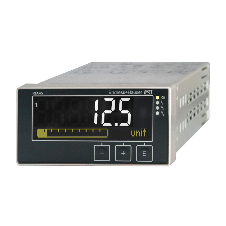
Operating elements and display RIA45 Display and device status indicator/LED The device provides an illuminated LC display which is split into two sections. The segment section displays the value of the channel and additional information and alarms. In the dot matrix section, additional channel information, such as the TAG, unit or bar graph, is displayed in the display mode. - Page 15 RIA45 Operating elements and display 5.3.2 Icons in the editing mode The following characters can be used to enter user-defined text: ‘0-9’, ‘a-z’, ‘A-Z’, ‘+’, ‘-’, ‘*’, ‘/’, ‘\’, ‘%’, ‘°’, ‘ ’, ‘ ’, ‘μ’, ‘.’, ‘,’, ‘;’, ‘:’, ‘!’, ‘?’, ‘_’, ‘#’, ‘$’, ‘"’, ‘´’, ‘(’, ‘)’, ‘~’...
-
Page 16: Quick Guide To The Operating Matrix
Operating elements and display RIA45 Quick guide to the operating matrix The following tables show all menus and the operating functions. Display menu Description AI1 Reset minmax* Reset the min/max values for Analog in 1 AI2 Reset minmax* Reset the min/max values for Analog in 2... - Page 17 RIA45 Operating elements and display Setup menu Description Analog in 1 Analog input 1 Signal type Signal type Signal range Signal range Connection Connection type (only for Signal type = RTD) Lower range Lower limit of measuring range Upper range...
- Page 18 Operating elements and display RIA45 Setup menu Description Relay 2 Relay 2 See Relay 1 Back Return to main menu *) Is only displayed if "Application" = "Diff pressure" is configured. Diagnostics menu Description Current diagn Current diagnostic Last diagn...
- Page 19 RIA45 Operating elements and display Expert menu Description Output Outputs The following parameters are available in addition to the parameters from the Setup menu: Analog out 1 / 2 Analog output 1 / 2 Fail mode Failure mode Fixed fail value...
-
Page 20: Commissioning
Commissioning RIA45 Commissioning Post-installation check and switching on the device Make sure that all post-connection checks have been carried out before you commission your device: • ‘Post-installation check’ checklist in Section 3.5 • ‘Post-connection check’ checklist in Section 4.2 Once the operating voltage is applied, the display lights up and the green LED indicates that the device is operational. -
Page 21: Configuring The Device
RIA45 Commissioning Configuring the device Configuration steps: Select the application conditions (only for 2-channel devices) (→ ä 21) Configure the universal input(s) (→ ä 24) Configure the calculations (→ ä 25) Configure the analog output(s) (→ ä 25) Configure relays (if option selected); assign and monitor limit values (→ ä 26) Advanced device configuration (access protection/operating code;... - Page 22 Commissioning RIA45 Differential pressure application A concise setup is available for differential pressure applications. Once the differential pressure application setup has been successfully completed, the configured parameters of the analog inputs and the linearization points are used to automatically form the difference between the two inputs and linearize the signal. As a result, the volume is already shown on the display (= calculated value 2).
- Page 23 RIA45 Commissioning ‘Setup’ menu item Setup → Application → ‘Diff pressure’ Preconfigured by Submenu application package Setup analog inputs ‘AI1 Lower range’: start of measuring range, analog input 1 (corresponds to → Signal: ‘Current’ 4 mA for example) → Range: ‘4-20 mA’...
- Page 24 Commissioning RIA45 6.4.2 Step 2: Configuring the universal input(s) (‘AnalogIn 1/2’) The device has one universal input, and optionally another universal input for current (‘Current’), voltage (‘Voltage’), resistance thermometer (‘RTD’) or thermocouples (‘TC’). The input is monitored for a cable open circuit (see "Measuring range limits" table (→ ä 36) and "Troubleshooting"...
- Page 25 RIA45 Commissioning 6.4.3 Step 3: Configuring the calculations One or two channels with the following functions are available for calculations: Setup Calc value 1 Calc value 2 • Switched off • Switched off • Sum (AI1+AI2) • Sum (AI1+AI2) • Difference (AI1-AI2) •...
- Page 26 Commissioning RIA45 6.4.5 Step 5: Configuring the relays, assigning and monitoring limit values As an option, the device has two relays with limit values, which are either switched off, or can be assigned to the input signal or the linearized value of analog input 1 or 2 or the calculated values.
- Page 27 RIA45 Commissioning Default setting Normally closed: Rest contact Rx1/Rx2 Operating modes No action is triggered. The output assigned is always in the normal operating mode. Min (lower limit value) The limit value is active if the value configured is undershot. The limit value is switched off again if the limit value incl.
- Page 28 Commissioning RIA45 Gradient The "Gradient" operating mode is used to monitor the change in the input signal over time. The alarm is triggered if the measured value reaches or overshoots the set value. If the user configures a positive value, the limit value is monitored for rising gradients.
- Page 29 RIA45 Commissioning Inband The limit value is violated as soon as the measured value to be checked drops below or exceeds a minimum or maximum value specified beforehand. The hysteresis is located at the insides of the band. Measured value...
- Page 30 Commissioning RIA45 6.4.6 Step 6: Advanced device configuration (access protection/ operating code, saving the current setup) Access protection The access protection locks all the editable parameters, i.e. setup can only be accessed once the 4-digit user code has been entered.
- Page 31 RIA45 Commissioning → Alternating time: select the time between automatic switchover between the channels and calculated values (in seconds: 3, 5, or 10) ‘x Back’ takes you back to the higher-order menu. If several channels are active, the device switches automatically between the channels configured.
- Page 32 Commissioning RIA45 Configuration when operating the device in accordance with TRbF510: The device must be set up and operated in accordance with these Operating Instructions which belong to the device. • Universal inputs have to be configured (as described in Step 1 - Step 3 (→ ä 21 ff.)).
- Page 33 RIA45 Commissioning Default values: Input type Default value Current and voltage inputs 0.0 s Temperature inputs 1.0 s Once 5 times the filter time have elapsed, 99% of the actual measured value is reached. a0010508 Fig. 13: Signal damping Analog in: analog input signal...
- Page 34 Commissioning RIA45 Output → Relay 1/2 Time delay Setting the time delay for relay switching. Operating mode Operating mode of the relay: • norm opened • norm closed Failure mode • norm opened • norm closed NOTICE Setting the limit relay failsafe mode ‣...
-
Page 35: In Operation
RIA45 Commissioning In operation 6.5.1 ‘+’ and ‘-’ quick pick keys You can use the ‘+’ and ‘-’ quick pick keys to switch through all the active channels (universal inputs and calculated values) in the display mode. The measured value or the calculated value is then displayed for 5 seconds. - Page 36 Commissioning RIA45 Measuring range limits Display Range - - - - - - - - - - Measured value - - - - - - - - - - - - - - - Special points to note Status Display...
- Page 37 RIA45 Commissioning 6.5.4 Saving diagnostic events/alarms and errors Diagnostic events such as alarms and fault conditions are saved in the device as soon as a new error occurs or the status of the device changes. The events saved are saved every 30 minutes to the nonvolatile device memory.
-
Page 38: Maintenance
Maintenance RIA45 Maintenance No special maintenance work is required on the device. Accessories NOTICE Possible malfunction caused by untested hardware when upgrading ‣ If you upgrade the device with additional hardware at a later date, (relay, additional universal input and additional analog output), an internal hardware test must be performed by the device software. -
Page 39: Troubleshooting
RIA45 Troubleshooting Troubleshooting NOTICE Possible malfunction caused by untested hardware when upgrading ‣ If you upgrade the device with additional hardware at a later date, (relay, additional universal input and additional analog output), an internal hardware test must be performed by the device software. You do so using the Verify HW set function in the Expert→Diagnostics menu. -
Page 40: Spare Parts
Fig. 14: Spare parts of process display unit Item Name Order No. Housing front with foil (incl. keyboard) RIA45X-DA Terminal cover Ex RIA45 71069920 CPU with LCD display incl. housing front RIA45T-A1 Mainboard Mainboard 20-250VDC/AC non-Ex RIA45X-NA Mainboard 20-250VDC/AC, Ex-version... -
Page 41: Return
RIA45 Troubleshooting Item Name Order No. Multifunction input cards, incl. terminals Multifunction input card for channel 2, non-Ex RIA45X-IA Multifunction input card for channel 2, Ex-version RIA45X-IB Relay card with 2 limit relays, incl. terminals RIA45X-RA Mounting kit RK01-AG Terminal, 3-pin for supply voltage... -
Page 42: Technical Data
Technical data RIA45 Technical data 10.0.1 Input Inputs One or two universal inputs Measured variable Current, voltage, resistance, resistance thermometer, thermocouples Measuring ranges Current: • 0/4 to 20 mA +10% overrange • Short-circuit current: max. 150 mA • Load: 10 Ω... - Page 43 RIA45 Technical data Output Output signal One or two analog outputs, galvanically isolated Current/voltage output Current output: • 0/4 to 20 mA • Overrange up to 22 mA Voltage: • 0 to 10 V, 2 to 10 V, 0 to 5 V, 1...5 V •...
- Page 44 Technical data RIA45 10.0.2 Terminal assignment Electrical connection a0010228 Fig. 15: Terminal assignment of panel meter (relays (terminals Rx1-Rx3) and channel 2 (terminals 21-28 and O25/O26) are optional) Supply voltage Wide-area power supply unit 24 to 230 V AC/DC (-20 % / +10 %) 50/60 Hz Power consumption Max.
- Page 45 RIA45 Technical data Performance Reference operating conditions characteristics Power supply: 230 V AC, 50/60 Hz Ambient temperature: 25 °C ± 5 °C (77 °F ± 9 °F) Humidity: 20 % to 60 % rel. humidity Maximum measured error Universal input:...
- Page 46 Technical data RIA45 Type R (Pt13Rh-Pt), -50 to 1768 °C (-58 to 3214 °F) (IEC60584) ± (0.15% oMR +3.5 K (6.3 °F)) for -50 to 100 °C (-58 to 212 °F) ± (0.15% oMR +1.5 K (2.7 °F)) for 100 to 1768 °C (212 to 3214 °F) Type U (Cu-CuNi), -200 to 600 °C (-328 to 1112 °F) (DIN 43710) ±...
- Page 47 RIA45 Technical data Climate class As per IEC 60654-1, Class B2 Degree of protection Front IP 65 / NEMA 4 (not evaluated by UL) Device casing/rear side IP 20 Condensation Front: permitted Device casing: not permitted Electrical safety Protection class I, overvoltage category II, pollution degree II Electromagnetic compatibility (EMC) •...
-
Page 48: Display Elements
Technical data RIA45 a0010351 Fig. 17: Panel cutout Weight Approx. 300 g (10.6 oz) Material • Housing: plastic PC-GF10 Terminals Plug-in spring terminals, 2.5 mm (14 AWG); auxiliary voltage with screw terminals (AWG 22-14; torque 0.4 Nm (3.5 lb in)). - Page 49 10.0.6 Certificates and approvals CE mark The device meets the legal requirements of the EU directives. Endress+Hauser confirms that the device has been tested successfully by affixing the CE mark. Ex approval Information about currently available Ex versions (ATEX, FM, CSA, etc.) can be supplied by your E+H Sales Center on request.
-
Page 50: Appendix
Appendix RIA45 Appendix The following tables show all the parameters available in the configuration menu. The values configured at the factory are marked in bold. 11.1 Further explanations on the differential pressure application at level measurement At both universal inputs pressure sensors are connected. - Page 51 RIA45 Appendix Conversion factors for various pressure engineering units: Pascal Technical Physical Torr Pounds per square Atmosphere Atmosphere inch (Pa) (bar) (at) (atm) (torr) (psi) ≡ 1 N/m ≡ 1 Mdyn/cm ≡ 1 kp/cm ≡ 1 pSTP ≡ 1 mmHg ≡...
- Page 52 Appendix RIA45 Calculation step: Calculation of the volume out of the height By means of the linearization of the calculated height value the volume can be calculated. This is done by assigning a certain volume value to every height value in dependency of the tank shape.
-
Page 53: Display Menu
RIA45 Appendix 11.2 Display menu Display menu AI1 Reset minmax Resets the minimum and maximum values saved for analog input 1. Only available if "Yes" was configured in the Setup→Analog in 1→Allow reset menu. AI2 Reset minmax Resets the minimum and maximum values saved for analog input 2. -
Page 54: Setup Menu
Appendix RIA45 11.3 Setup menu Setup menu Application 1-channel Configures the application for the process display unit. 2-channel 2-channel is the default setting for two-channel devices, 1-channel for Diff pressure single-channel devices. Configures the measuring range lower limit AI1 Lower range Numerical value Only visible if →... - Page 55 RIA45 Appendix Setup menu Signal range 4-20mA, 4- Configures the input signal 20mA squar, 0-20mA, 0-20mA squar, 0-10V, 0-10V squar, 0-5V, 2-10V, 1-5V, 1-5V squar, 0-1V, 0-1V squar, +/- 1V, +/- 10V, +/- 30V, +/- 100mV Pt46GOST, Pt50GOST, Pt100IEC, Pt100JIS,...
- Page 56 Appendix RIA45 Setup menu Signal range 4-20mA, 4- Configures the input signal 20mA squar, 0-20mA, 0-20mA squar, 0-10V, 0-10V squar, 0-5V, 2-10V, 1-5V, 1-5V squar, 0-1V, 0-1V squar, +/- 1V, +/- 10V, +/- 30V, +/- 100mV Pt46GOST, Pt50GOST, Pt100IEC, Pt100JIS,...
- Page 57 RIA45 Appendix Setup menu Customized text, max. Channel name 12 digits Unit Customized text, max. Unit of the channel 5 digits Bar 0% Numerical value Configures the 0%-value for the bar graph Bar 100% Numerical value Configures the 100%-value for the bar graph...
- Page 58 Appendix RIA45 Setup menu Reset min/max Resets the min./max. values saved. Analog Out 1 Assignment Selects the source for the output signal Analog 1 Analog 2 Calc value 1 Calc value 2 Signal type 4-20mA Selects the type of signal for the output signal...
-
Page 59: Diagnostics Menu
RIA45 Appendix Setup menu Function Function of the relay Gradient Inband Outband Setpoint Numerical value Switching threshold for relay Setpoint 2 Numerical value Second switching threshold for relay Only for the inband and outband functions. Time base 0-60 Time base for gradient calculation in seconds Only visible if "Function"... - Page 60 Appendix RIA45 Expert menu Bar 100% Numerical value Configures the 100%-value for the bar graph Decimal places XXXXX Configures the number of decimal XXXX.X places for the display XXX.XX XX.XXX X.XXXX Damping Numerical value Configures the damping for the 0.0 for current/voltage input signal.
- Page 61 RIA45 Appendix Expert menu Open circ detect Sets cable open circuit detection. Only visible if "1-5 V" is configured as the signal range. Allow reset Setting as to whether saved min./ max. values can be reset in the Display menu without having to enter a user code which may already have been configured.
- Page 62 Appendix RIA45 Expert menu Allow reset Setting as to whether saved min./ max. values can be reset in the Display menu without having to enter a user code which may already have been configured. Calc value 2 Decimal places XXXXX Configures the number of decimal XXXX.X...
-
Page 63: Index
RIA45 Index Access protection....... . 30 Measuring range limits ......36 Analog output Min./max. - Page 64 www.addresses.endress.com...