Endress+Hauser RIA452 Brief Operating Instructions
Panel meter
Hide thumbs
Also See for RIA452:
- Operating instructions manual (236 pages) ,
- Brief operating instructions (56 pages) ,
- Technical information (15 pages)
Table of Contents
Advertisement
Available languages
Available languages
Quick Links
Advertisement
Chapters
Table of Contents

Related Manuals for Endress+Hauser RIA452


Summary of Contents for Endress+Hauser RIA452
- Page 1 Brief Operating Instructions RIA452 Panel meter RIA452 Endress+Hauser 2573 m³/min ; Prozessanzeiger (ab Seite 2) < Panel meter (from page 21) = Indicateur de process (à partir de page 38) KA264R/09/a3/06.08 71071918 SW Version 2.01.00...
-
Page 3: Table Of Contents
Prozessanzeiger Inhaltsverzeichnis Inhaltsverzeichnis 1 Sicherheitshinweise..........4 1.1 Bestimmungsgemäße Verwendung . -
Page 4: Sicherheitshinweise
Sicherheitshinweise Prozessanzeiger Sicherheitshinweise Ein sicherer und gefahrloser Betrieb des Prozessanzeigers ist nur sichergestellt, wenn diese Betriebsanleitung gelesen und die Sicherheitshinweise darin beachtet werden. Bestimmungsgemäße Verwendung Der Prozessanzeiger bewertet analoge Prozessgrößen und stellt diese an seinem mehrfarbigen Display dar. Mittels seinen Ausgängen sowie Grenzwertrelais können Prozesse überwacht und gesteuert werden. -
Page 5: Sicherheitszeichen Und -Symbole
Prozessanzeiger Sicherheitshinweise Sicherheitszeichen und -symbole Sicherheitshinweise in dieser Betriebsanleitung sind mit folgenden Sicherheitszeichen und -symbolen gekennzeichnet: " Achtung! Dieses Symbol deutet auf Aktivitäten oder Vorgänge hin, die - wenn sie nicht ordnungsgemäß durchgeführt werden - zu fehlerhaftem Betrieb oder zur Zerstörung des Gerätes führen können. Warnung! Dieses Symbol deutet auf Aktivitäten oder Vorgänge hin, die - wenn sie nicht ordnungsgemäß... -
Page 6: Identifizierung
Identifizierung Prozessanzeiger Identifizierung Gerätebezeichnung 2.1.1 Typenschild Vergleichen Sie das Typenschild am Gerät mit der folgenden Abbildung: Order Code: RIA452-A211A11A Ser.No.: 12345B123BE 20-36V 20-28V 50/60Hz Software: ILU10xA 24VA -20°C (-4°F) < Ta < 60°C (140°F) Made in Germany 20XX G09-RIA452xx-18-00-xx-xx-000 Abb. 1: Typenschild des Prozessanzeigers (beispielhaft) Bestellcode und Seriennummer des Gerätes... -
Page 7: Zertifikate Und Zulassungen
Prozessanzeiger Montage Zertifikate und Zulassungen CE-Zeichen, Konformitätserklärung Der Prozessanzeiger ist nach dem Stand der Technik betriebssicher gebaut und geprüft und hat das Werk in sicherheitstechnisch einwandfreiem Zustand verlassen. Das Gerät berücksichtigt die einschlägigen Normen und Vorschriften nach IEC 61 010-1 "Sicherheitsbestimmungen für elektrische Mess-, Steuer-, Regel- und Laborgeräte". - Page 8 Montage Prozessanzeiger G09-RIA452xx-17-01-06-xx-001 Abb. 2: Einbau in Schalttafel Schieben Sie das Gerät mit Dichtring (Pos. 1) von vorne durch den Schalttafelausschnitt. Halten Sie das Gerät waagerecht und hängen Sie die beiden Befestigungsspangen (Pos. 2) in die dafür vorgesehenen Aussparungen ein. Ziehen Sie die Schrauben der Befestigungsspangen gleichmäßig mit einem Schraubendre- her an.
-
Page 9: Verdrahtung
Prozessanzeiger Verdrahtung Verdrahtung Verdrahtung auf einen Blick G09-RIA452ZZ-04-01-xx-de-000 Abb. 3: Klemmenbelegung des Prozessanzeigers (Universaleingang s. Seite 12) - Page 10 Verdrahtung Prozessanzeiger Klemmenbelegung Klemme Klemmenbelegung L/L+ L für AC L+ für DC Hilfsenergie N/L- N für AC L- für DC Not connected Jumper zur hardwaremäßigen Verriegelung der Gerä- Hinweis! tebedienung. Ist Jumper auf J1 gesteckt, kann die Ein- Das Gerät ist immer mit der PC-Software über RS232 stellung nicht verändert werden.
- Page 11 Prozessanzeiger Verdrahtung Klemme Klemmenbelegung Normally closed (NC) Common (COM) Relais 4 Normally open (NO) Normally closed (NC) Common (COM) Relais 5 (Optional) Normally open (NO) Normally closed (NC) Common (COM) Relais 6 (Optional) Normally open (NO) Normally closed (NC) Common (COM) Relais 7 (Optional) Normally open (NO) Normally closed (NC)
- Page 12 Verdrahtung Prozessanzeiger Klemme Klemmenbelegung + Digitalausgang Digitalausgang (Optional) Masse Digitalausgang 24V Sensorversorgung 2 Messumformerspeisung Masse Sensorversorgung 2 Option Universaleingang Anstelle des Stromeingangs kann das Gerät optional mit einem Universaleingang ausgerüstet werden. G09-RIA452xx-04-10-xx-de-002 Abb. 4: Klemmenbelegung Universaleingang...
-
Page 13: Anschluss Des Gerätes
Prozessanzeiger Verdrahtung Klemmenbelegung Klemme Klemmenbelegung + 0/4 bis 20 mA Signal Signalmasse (Strom, Spannung, Temperatur) + 1 V, + Thermoelemente, - Widerstandsthermometer Signal (3-/4-Leiter) + Widerstandsthermometer Signal (4-Leiter) + 30 V + Widerstandsthermomenter Versorgung (3-/4-Leiter) Anschluss des Gerätes " Achtung! Gerät nicht unter Netzspannung installieren bzw. - Page 14 Verdrahtung Prozessanzeiger 4.2.2 Anschluss externer Sensoren Hinweis! An das Gerät können aktive und passive Sensoren mit Analog-, TC, Widerstand und RTD Sen- soren angeschlossen werden. Die Anschlussklemmen sind, abhängig vom Signaltyp des jeweiligen Sensors, frei wählbar. Stromeingang 0/4...20 mA G09-RIA452xx-04-10-xx-de-001 Abb.
-
Page 15: Anschlusskontrolle
Prozessanzeiger Verdrahtung Anschlusskontrolle Gerätezustand und -spezifikationen Hinweise Sind Gerät oder Kabel beschädigt (Sichtkontrolle)? Elektrischer Anschluss Hinweise Stimmt die Versorgungsspannung mit den Angaben auf dem Typenschild überein? 90 bis 250 V AC (50/60 Hz) 20 bis 36 V DC 20 bis 28 V AC (50/60 Hz) Sind alle Klemmen in ihrem richtigen Steckplatz fest eingerastet? Stimmt die Codie- rung auf den einzelnen Klemmen? Sind die Kabel zugentlastet montiert? -
Page 16: Bedienung Und Inbetriebnahme
Bedienung und Inbetriebnahme Prozessanzeiger Bedienung und Inbetriebnahme Bedienung auf einen Blick Detaillierte Informationen zur Bedienung des Gerätes, zur Parametrierung, Hinweise sowie eine Beschreibung der einzelnen Funktionalitäten finden Sie in der Betriebsanleitung auf der mitge- lieferten CD-ROM. Eine Übersicht aller Bedienparameter ist im Kapitel 5.1 der Betriebsanlei- tung dargestellt. -
Page 17: Vor-Ort-Bedienung
Prozessanzeiger Bedienung und Inbetriebnahme Bereich Anzeige Relais Analogausgang Integration Eingangsstrom über " " anzeigen normales Grenz- Normales Verhalten Normales Verhalten unterer Fehler- wertverhalten mit max. 10% Über- (negative Integra- grenze und unterhalb bereich. Keine Aus- tion nicht möglich) unterer Gültigkeits- gabe <... - Page 18 Bedienung und Inbetriebnahme Prozessanzeiger 5.3.1 Bedienung über das Drehrad A) 3-Tastenfunktion • Drücken = "Enter" • Drehen im Uhrzeigersinn = "+" • Drehen gegen den Uhrzeigersinn = "-" G09-RIA452ZZ-19-00-00-xx-002 Abb. 9: Bedienung über Drehrad B) Listenauswahl Æ Pfeil nach unten: Auswahl steht am Anfang der Auswahlliste.
- Page 19 Prozessanzeiger Bedienung und Inbetriebnahme Pos.-Nr. Beschreibung Aktivieren Sie das Bedienmenü indem Sie das Bedienrad für mindestens 3 sec drücken. Anschließend blinkt das erste Zeichen. Durch Drehen des Drehrades können Sie das blinkende (ausgewählte) Zeichen ändern (siehe "Mögliche Zeichenmenge" nächster Absatz). Sie können zum vorherigen Zeichen zurückkehren, indem Sie das Rück- sprungsymbol (Pfeil nach links) auswählen.
-
Page 20: Installationskontrollen
Bedienung und Inbetriebnahme Prozessanzeiger G09-RIA452ZZ-19-00-00-xx-004 Abb. 12: Position des Jumpers auf der Geräterückseite Hinweis! Auf die PC-Bediensoftware hat die Hardware-Verriegelung keine Auswirkung. Installationskontrollen Vergewissern Sie sich, dass alle Abschlusskontrollen durchgeführt wurden, bevor Sie Ihr Gerät in Betrieb nehmen: • Checkliste Kap. 4.3 'Anschlusskontrolle' Hinweis! Entfernen Sie die Schutzfolie vom Display, da ansonsten die Ablesbarkeit eingeschränkt ist. - Page 21 Process Display Table of contents Table of contents 1 Safety instructions ..........22 1.1 Designated use .
-
Page 22: Safety Instructions
Safety instructions Process Display Safety instructions Safe operation of the process display unit is only guaranteed if these Operating Instructions have been read and the safety instructions have been observed. Designated use The process display unit analyzes analog process variables and depicts them on its multicolored display. -
Page 23: Notes On Safety Conventions And Icons
This symbol indicates an action or procedure which, if not performed correctly, can have an indirect effect on operation or trigger an unexpected response on the part of the device. Identification Device designation 2.1.1 Nameplate Compare the nameplate on the device with the following diagram: Order Code: RIA452-A211A11A Ser.No.: 12345B123BE 20-36V 20-28V 50/60Hz Software:... -
Page 24: Scope Of Delivery
Installation Process Display Scope of delivery The scope of delivery of the process display unit comprises: • Process display unit for panel mounting • Multilanguage Brief Operating Instructions as hard copy • Operating Instructions on CD-ROM • CD-ROM with PC configuration software and interface cable RS232 (optional) •... -
Page 25: Installation Instructions
Process Display Installation Installation instructions The required panel cutout is 92x92 mm (3.62x3.62 inches). Please note the installation depth of 150 mm (5.91 inches) for the measuring device plus cable. G09-RIA452xx-17-01-06-xx-001 Fig. 2: Installation in panel Push the device with the sealing ring (item 1) through the panel cutout from the front. Keep the device horizontal and suspend the two fixing clips (item 2) in the recesses provided. -
Page 26: Wiring
Wiring Process Display Wiring Quick wiring guide G09-RIA452ZZ-04-01-xx-en-000 Fig. 3: Terminal assignment of the process display unit (universal input → Page 29) - Page 27 Process Display Wiring Terminal assignment Terminal Terminal assignment Type L/L+ L for AC L+ for DC Power supply N/L- N for AC L- for DC Not connected Jumper for locking device operation via hardware. If Note! the jumper is set to J1, the configuration cannot be The device can always be configured with the PC modified.
- Page 28 Wiring Process Display Terminal Terminal assignment Type Normally closed (NC) Common (COM) Relay 4 Normally open (NO) Normally closed (NC) Common (COM) Relay 5 (optional) Normally open (NO) Normally closed (NC) Common (COM) Relay 6 (optional) Normally open (NO) Normally closed (NC) Common (COM) Relay 7 (optional) Normally open (NO)
- Page 29 Process Display Wiring Terminal Terminal assignment Type + digital output Digital output (optional) Ground, digital output 24 V sensor power supply 2 Transmitter power supply Ground, sensor power supply 2 Universal input option The device can be optionally equipped with a universal input instead of a current input. G09-RIA452xx-04-10-xx-en-002 Fig.
-
Page 30: Connecting The Device
Wiring Process Display Terminal assignment Terminal Terminal assignment + 0/4 to 20 mA signal Signal ground (current, voltage, temperature) + 1 V, + thermocouples, - resistance thermometer signal (3/4 wire) + resistance thermometer signal (4-wire) + 30 V + resistance thermometer power supply (3-wire/4-wire) Connecting the device "... - Page 31 Process Display Wiring 4.2.2 Connecting external sensors Note! Active and passive sensors with analog, TC, resistance and RTD sensors can be attached to the device. Depending on the type of signal of the sensor in question, the terminals can be freely selected. Current input 0/4 to 20 mA G09-RIA452xx-04-10-xx-en-001 Fig.
-
Page 32: Post-Connection Check
Operation and commissioning Process Display Post-connection check Device condition and specifications Notes Is the device or cable damaged (visual inspection)? Electrical connection Notes Does the supply voltage match the specifications on the nameplate? 90 to 250 V AC (50/60 Hz) 20 to 36 V DC 20 to 28 V AC (50/60 Hz) Are all of the terminals firmly engaged in their correct slots? Is the coding... -
Page 33: Display And Operating Elements
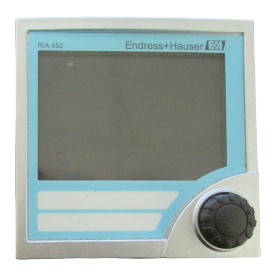
Process Display Operation and commissioning Display and operating elements Note! Remove the protective strip from the display as this restricts display legibility otherwise. 123467 89 G09-RIA452xx-19-00-06-xx-000 Fig. 8: Display and operating elements Green operating indicator, lights up when supply voltage is applied Red fault indicator, flashes in event of sensor or device error Limit value display: if power is supplied to a relay, the symbol is displayed. -
Page 34: Local Operation
Operation and commissioning Process Display Range Display Relay Analog output Totalizer Input current below Display " " Normal limit value Normal behavior Normal behavior upper error limit and behavior with max. 10% (negative totalizing above upper overrange. No not possible) limitations of validity output <... - Page 35 Process Display Operation and commissioning B) Selection from list Æ Arrow pointing down: Option is at the top of the picklist. The other entries become visible when the jog/shuttle is turned in the clockwise direction. Å Both arrows visible: Æ User is in the middle of the picklist.
- Page 36 Operation and commissioning Process Display Possible characters The following characters can be entered: Space +ABCDEFGHIJKLMNOPQRSTUVWXYZabcdefghijklmnopqrstuvwxyz0123456789/\%° +-.; :*() followed by return symbol (arrow to left) 5.3.3 Disabling the programming mode User code The configuration can be protected against unintentional access by means of a four-digit code. This code is defined in menu item 55 "Parameter/user code".
-
Page 37: Function Check
Process Display Operation and commissioning Function check Make sure that all post-connection checks have been carried out before you commission your device: • Checklist Section 4.3 'Post-connection check' Note! Remove the protective strip from the display as this restricts display legibility otherwise. Switching on the measuring device Once the operating voltage is applied, the green LED indicates that the device is operational. - Page 38 Indicateur de process Les présentes instructions sont condensées. Des informations détaillées figurent dans le manuel de mise en service et les documentations supplémentaires sur le CD-RO fourni. Ces instructions condensées ne remplacent pas le manuel de mise en service. La documentation d'appareil complète comprend : •...
- Page 39 Indicateur de process Sommaire Sommaire 1 Conseils de sécurité ..........40 1.1 Utilisation conforme .
-
Page 40: Conseils De Sécurité
Conseils de sécurité Indicateur de process Conseils de sécurité Un fonctionnement sûr et sans danger de l'indicateur de process est seulement assuré si les présentes instructions de mise en service ont été lues et si les conseils de sécurité ont été suivis. Utilisation conforme L'indicateur de process exploite des grandeurs de process analogiques et les affiche en plusieurs couleurs. -
Page 41: Symboles De Sécurité
Indicateur de process Conseils de sécurité Symboles de sécurité Les conseils de sécurité figurant dans le présent manuel sont mis en évidence à l'aide des symboles suivants : " Attention ! Ce symbole signale les actions ou procédures risquant d'entraîner des dysfonctionnements ou la destruction de l'appareil si elles ne sont pas menées correctement. -
Page 42: Identification
Identification Indicateur de process Identification Désignation de l'appareil 2.1.1 Plaque signalétique Comparer la plaque signalétique sur l'appareil avec la figure suivante : Order Code: RIA452-A211A11A Ser.No.: 12345B123BE 20-36V 20-28V 50/60Hz Software: ILU10xA 24VA -20°C (-4°F) < Ta < 60°C (140°F) -
Page 43: Certificats Et Agréments
Indicateur de process Montage Certificats et agréments Marque CE, déclaration de conformité L'indicateur de process a été construit et contrôlé dans les règles de l'art. Il a quitté nos établis- sements dans un état technique parfait. Il a été construit selon CEI 61 010 -1 - "Directives de sécurité... -
Page 44: Montage
Montage Indicateur de process Montage La découpe d'armoire nécessaire est de 92x92 mm (3,62x3,62 Inches). Tenir compte de la profondeur de montage de 150 mm (5,91 Inches) pour l'appareil + le câble. G09-RIA452xx-17-01-06-xx-001 Fig. 2 : Montage en armoire électrique Insérer l'appareil avec le joint (Pos. -
Page 45: Câblage
Indicateur de process Câblage Câblage Câblage en bref G09-RIA452ZZ-04-01-xx-de-000 Fig. 3 : Occupation des bornes de l'indicateur de process (entrée universelle v. page 48) - Page 46 Câblage Indicateur de process Occupation des bornes Borne Occupation des bornes Nature L/L+ L pour AC L+ pour DC Alimentation principale N/L- N pour AC L- pour DC Non raccordé Cavalier pour le verrouillage de la commande de Remarque ! l'appareil.
- Page 47 Indicateur de process Câblage Borne Occupation des bornes Nature Normalement fermé (NC) Commun (COM) Relais 4 Normalement ouvert (NO) Normalement fermé (NC) Commun (COM) Relais 5 (en option) Normalement ouvert (NO) Normalement fermé (NC) Commun (COM) Relais 6 (en option) Normalement ouvert (NO) Normalement fermé...
- Page 48 Câblage Indicateur de process Borne Occupation des bornes Nature + sortie digitale Sortie digitale (option) Masse sortie digitale 24 V alimentation capteur 2 Alimentation de transmetteur Masse alimentation capteur 2 Option entrée universelle A la place de l'entrée courant, l'appareil peut être équipé en option d'une entrée universelle. G09-RIA452xx-04-10-xx-de-002 Fig.
-
Page 49: Raccordement De L'appareil
Indicateur de process Câblage Occupation des bornes Borne Occupation des bornes Signal + 0/4 à 20mA Masse signal (courant, tension, température) +1 V, + thermocouples, - signal thermorésistances (3/4 fils) + signal thermorésistances (4 fils) + 30 V + alimentation thermorésistances (3/4 fils) Raccordement de l'appareil "... - Page 50 Câblage Indicateur de process 4.2.2 Raccordement de capteurs externes Remarque ! Il est possible de raccorder à l'appareil des capteurs actifs ou passifs avec des signaux analogiques, thermocouples, thermorésistances ainsi que des capteurs RTD. Les bornes de raccordement sont au choix, en fonction du type de signal du capteur correspon- dant.
-
Page 51: Contrôle Du Raccordement
Indicateur de process Câblage Contrôle du raccordement Etat et spécifications de l'appareil Remarques L'appareil ou le câble est-il endommagé (contrôle visuel) ? Raccordement électrique Remarques La tension d'alimentation concorde-t-elle avec les indications figurant sur la plaque 90 à 250 V AC (50/60 Hz) signalétique ? 20 à... -
Page 52: Utilisation Et Mise En Service
Utilisation et mise en service Indicateur de process Utilisation et mise en service Utilisation en bref Des informations détaillées sur l'utilisation de l'appareil, le paramétrage, les recommandations ainsi que les différentes fonctionnalités se trouvent dans le manuel de mise en service sur le CD-ROM fourni. -
Page 53: Utilisation Sur Site
Indicateur de process Utilisation et mise en service 5.2.1 Représentation des affichages Gamme Affichage Relais Sortie Intégration analogique Courant d'entrée Affiche Etat d'erreur Mode défaut réglé Pas d'intégration sous le seuil d'erreur " " inférieur Courant d'entrée > Affiche Commutation de Comportement Comportement au seuil d'erreur infé-... - Page 54 Utilisation et mise en service Indicateur de process 5.3.1 Utilisation via le bouton rotatif A) Touche 3 fonctions • Appuyer = "Enter" • Rotation dans le sens horaire = "+" • Rotation dans le sens anti-horaire = "-" G09-RIA452ZZ-19-00-00-xx-002 Fig. 9: Utilisation via le bouton rotatif B) Sélection de liste Æ...
- Page 55 Indicateur de process Utilisation et mise en service Pos. Description Accès au menu d'exploitation en activant la bouton rotatif pendant plus de 3 s. Le premier caractère clignote. En tournant le bouton rotatif on peut modifier le caractère clignotant (sélectionné) (voir "Quantité de carac- tères possible", prochain paragraphe).
-
Page 56: Contrôles De L'installation
Utilisation et mise en service Indicateur de process G09-RIA452ZZ-19-00-00-xx-004 Fig. 12 : Position du cavalier au dos de l'appareil Remarque ! Le verrouillage du hardware n'a aucun effet sur le logiciel PC. Contrôles de l'installation Il convient de s'assurer que tous les contrôles finaux ont été effectués avant de mettre l'appareil en service : •... - Page 57 Indicateur de process Utilisation et mise en service...
- Page 60 www.endress.com/worldwide KA264R/09/a3/06.08 71071918 FM+SGML6.0 ProMoDo...