Table of Contents
Advertisement
Quick Links
.
HD MEMORY CARD CAMERA RECORDER
GY-HM890U/GY-HM890E
GY-HM890CHU/GY-HM890CHE
GY-HM890RE/GY-HM890RCHE
GY-HM850U/GY-HM850E
GY-HM850CHU/GY-HM850CHE
GY-HM850RE/GY-HM850RCHE
INSTRUCTIONS
.
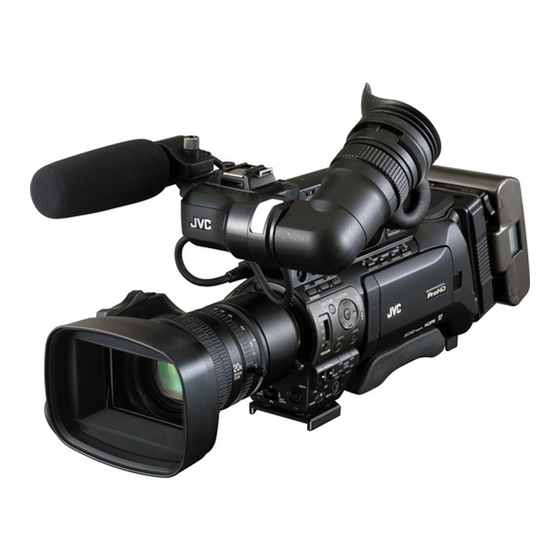
In this illustration, the supplied viewfinder, microphone, and lens are attached to the GY-HM890U/GY-
HM890E/GY-HM890RE.
The lens is not supplied for GY-HM890CHU/GY-HM890CHE/GY-HM890RCHE and GY-HM850CHU/
GY-HM850CHE/GY-HM850RCHE.
The specifications and appearance of this product are subject to changes for further improvement
without prior notice.
Please check the latest version of the INSTRUCTIONS from the following Mobile User Guide. You can
also download the PDF from the Mobile User Guide.
Mobile User Guide
When you are outside, you can refer to the instructions from your Android phone or iPhone.
http://manual3.jvckenwood.com/pro/mobile/global/
You can view the Mobile User Guide using the browser on your Android phone or iPhone.
For Customer Use:
Enter below the Serial No. which is located
on the body.
Retain this information for future reference.
Model No.
GY-HM890U / GY-HM890CHU
GY-HM850U / GY-HM850CHU
Serial No.
IM 1.04
Please read the following before getting started:
Thank you for purchasing this product.
Before operating this unit, please read the
instructions carefully to ensure the best
possible performance.
In this manual, each model number is
described without the last letter (U/E) which
means the shipping destination.
(U: for USA and Canada, E: for Europe)
Only "U" models (GY-HM890U/GY-HM890CHU/
GY-HM850U/GY-HM850CHU) have been
evaluated by UL.
LST1584-001B
Advertisement
Table of Contents

Related Manuals for JVC GY-HM890U


Summary of Contents for JVC GY-HM890U
- Page 1 GY-HM850U/GY-HM850E GY-HM850CHU/GY-HM850CHE GY-HM850RE/GY-HM850RCHE INSTRUCTIONS In this illustration, the supplied viewfinder, microphone, and lens are attached to the GY-HM890U/GY- HM890E/GY-HM890RE. The lens is not supplied for GY-HM890CHU/GY-HM890CHE/GY-HM890RCHE and GY-HM850CHU/ GY-HM850CHE/GY-HM850RCHE. The specifications and appearance of this product are subject to changes for further improvement without prior notice.
-
Page 3: Safety Precautions
Safety Precautions Slots and openings in the cabinet and the back or bottom are provided for IMPORTANT SAFEGUARDS ventilation, and to insure reliable operation of the appliance and to protect it from overheating, these Read all of these instructions. openings must not be blocked or Save these instructions for later use. - Page 4 CAUTION: Upon completion of any service or CHANGES OR MODIFICATIONS NOT repairs to this appliance, ask the APPROVED BY JVC COULD VOID service technician to perform routine USER’S AUTHORITY TO OPERATE safety checks to determine that the THE EQUIPMENT.
- Page 5 Information for USA POUR CANADA This device complies with part 15 of the FCC Rules. Changes or modifications ATTENTION not approved by JVC KENWOOD could RISQUE void the user's authority to operate the D’ELECTROCUTION equipment. NE PAS OUVRIR This equipment has been tested and...
- Page 6 CAUTION: European representative of This unit should be used with 12V DC only. JVC KENWOOD Corporation is: To prevent electric shocks and fire hazards, JVCKENWOOD Deutschland Gmbh do NOT use anyother power source. Konrad-Adenauer-Allee 1-11...
- Page 7 FOR EUROPE Para Brasil This equipment is in conformity with the Informação sobre eliminação de provisions and protection requirements of the baterias corresponding European Directives. This equipment is designed for professional video Este produto não deverá ser eliminado appliances and can be used in the following como lixo doméstico em geral.
- Page 8 Safety Precautions...
-
Page 9: Table Of Contents
Contents Clips Recorded to SD Cards ......47 About the Operation Lock Feature ....48 Introduction Shooting Safety Precautions ..........3 Basic Shooting Procedures ......49 Contents ............9 Selecting a Recording Format ......50 Main Features ..........12 Zoom Operation ..........52 Precautions for Proper Use ...... - Page 10 Selecting Multiple Clips Randomly ..... 100 Connecting Wired Remote Control ....164 Selecting Multiple Clips Consecutively ..101 Connecting a Remote Control Unit ....164 Trimming Recorded Clips ......102 Functions Operable from the Remote Control Unit ............... 166 Menu Display and Detailed Settings Inputting SDI Signals from an External Device A Basic Operations in Menu Screen ....
- Page 11 Others Error Messages and Actions ......202 List of FTP Transfer Errors ......203 List of Live Streaming Error Displays ..205 Blinking of the Tally Lamp ......206 Warning Tone ..........206 Troubleshooting ..........206 Specifications ..........209 Index ............. 214 Software License Agreement ......
-
Page 12: Main Features
ND filter (OFF, 1/4, 1/16, 1/64). recording feature, allowing for HD recording to one of the SDHC/SDXC cards, and SD or proxy video JVC’s Proprietary FALCONBRID High- recording to the other card at the same time. Quality Imaging Engine... - Page 13 (For MP4 file format) The disc provided with this camera recorder 0.45-inch 1.22-megapixel color viewfinder, comes with [JVC ProHD Clip Manager] and other 4.3-inch 1.15-megapixel LCD display application software as well as their user guides. (Equipped with Focus Assist function) * For details, refer to the user guides for each application software.
-
Page 14: Precautions For Proper Use
Precautions for Proper Content of this manual All rights reserved by JVC KENWOOD Corporation. Unauthorized duplication or reprinting of this manual, in whole or in part, is Storage and Usage Locations strictly prohibited. Illustrated designs, specifications and other o Allowable ambient temperature and humidity... - Page 15 Carrying the Camera GPS l Do not drop or hit this unit against a hard object o The GPS (Global Positioning System) satellites when transporting. are managed by the Department of State of the U.S., and its precision may be altered intentionally. Power Saving o Perform positioning at an unobstructed location with a clear view that is not indoors or blocked by...
- Page 16 o Do not remove the labels or stick other labels or SDHC/SDXC Cards stickers on the SD cards. o SDHC/SDXC card is referred to as “SD card” in o Do not use pencils or ballpoint pens to write on this manual. the SD cards.
- Page 17 Copyright Others Any recordings made on this camera recorder that o Do not insert objects other than the memory card are played back for profit or public preview may into the card slot. infringe on the rights of the owner of the recordings. o Do not block the vent on the unit.
-
Page 18: Operation Modes
Operation Modes This camera recorder has four operation modes - Camera mode, Media mode, USB mode and Remote Edit mode. Camera Mode Media Mode Press and hold [CAM/MEDIA] [CANCEL]/[MENU/THUMB] Button Camera Input Playback Thumbnail Display Normal Playback Playback Switch from Button [CAM/MEDIA] Trimming Playback... - Page 19 Operation Mode Description Camera Mode This is the camera shooting mode. The camera recorder starts up in Camera mode when the power is turned on. Camera images are output on the viewfinder and LCD monitor. When a recordable SD card is inserted, the camera recorder enters the recording standby mode.
-
Page 20: Names Of Parts
Names of Parts A Front Tally Lamp It is used to switch the color temperature of (A P42 [Tally Lamp] ) the preset white balance when the [WHT.BAL B/A/PRESET] switch J on the (A P206 [Blinking of the Tally Lamp] ) operation panel located at the right side of B Viewfinder Cable Clamp this unit is set to “PRESET”. - Page 21 HOLD J [MONITOR SELECT] Audio Monitor Selection U Lens Cable Clamp (A P28 [Attaching the Lens (Supplied)] ) Switch (A P72 [Audio Output during Recording] ) V [AUDIO INPUT] Audio Input Signal Selection K Monitor Speaker (Cheek Pad) Switch 1/2 (A P97 [Audio Output during Playback] ) (A P69 [Audio Recording] ) L Shoe...
-
Page 22: Side Control Panel
Side Control Panel F [MENU/THUMB] Menu/Thumbnail Button Displays the menu screen during Camera mode. Switches between [Main Menu] and [Favorites Menu] when the [MENU/THUMB] button is pressed and held down while the menu screen is displayed. (A P103 [Basic Operations in Menu Screen] ) Displays the menu screen when the button is pressed during thumbnail display in the Media mode. -
Page 23: Viewfinder
Viewfinder O Cross-Shaped Button (JKHI)/Set Button (R) The function changes according to the (A P40 [Adjusting the Viewfinder] ) operation status of the camera recorder. o During menu operation (all modes) (A P103 [Basic Operations in Menu Screen] ) Set Button (R) : Confirms menu items and setting values Cross-shaped Button... -
Page 24: Lcd Monitor
LCD Monitor Side Terminal Section * GY-HM890U/GY-HM890E/GY-HM890CHU/ GY-HM890CHE/GY-HM890RE/GY- HM890RCHE is used in the illustration here. A [HD/SD SDI IN] HD/SD SDI Input Terminal A LCD Monitor (BNC) A B (A P38 [Adjusting the LCD Monitor and (A P168 [Inputting SDI Signals from an... -
Page 25: Sd Slot
Rear Terminal J [AUDIO OUTPUT CH-1/3, CH-2/4] Audio Output Terminal (RCA) Output terminal for audio signals. Input audio signals are output during Camera mode. Playback audio signals are output during Media mode. In the SDI signal input mode, audio signals superimposed with the SDI input are output. -
Page 26: Lens Section A C
Lens Section A C F Zoom Servo Connector This is a connector for connecting a zoom servo unit (sold separately). When using a separately sold zoom servo unit, set the [ZOOM SERVO/ MANUAL] switch H to “SERVO”. G [F.f] Back Focus Button and Indicator Lamp (A P41 [Adjusting Back Focus] ) H [ZOOM SERVO/MANUAL] Zoom Operation Servo/Manual Switch... -
Page 27: Basic System Diagram
Basic System Diagram Caution : VF-HP840U does not function even when it is connected to this camera recorder. Wireless Microphone Camera Recorder Receiver Shoulder Belt [SDI OUT] SDI Cable BNC Composite Cable Earphone Monitor Audio Cable RCA pin Focus Manual Unit HDMI Cable [AUX] [SDI IN]... -
Page 28: Settings And Adjustments Before Use
[INPUT1] or [INPUT2] terminal. may be out of alignment. 5 Pin the microphone cable to the clamp. Lens is supplied for GY-HM890U, GY-HM890E, 6 Perform the settings for the phantom mic GY-HM890RE, GY-HM850U, GY-HM850E and correctly. -
Page 29: Opening/Closing The Lens Cover A C
Attaching/Detaching the Hood A C 3 Attach the viewfinder cable to the viewfinder terminal. Attaching the Hood 4 Pin the viewfinder cable to the clamp. Align the markings on the camera recorder and hood; turn the hood in the direction of the arrow until it is locked. -
Page 30: Attaching The Anti-Reflective Film
Power Supply Attaching the Anti-reflective Film Attach the supplied anti-reflective film onto the LCD monitor if necessary, such as when you are To use this camera recorder, you can attach a recording in the day or outdoors. battery pack or connect an AC adapter to it. Doing so helps to cut down reflection of outside (A P31 [Using a Battery Pack] ) light, thus improving the visibility. -
Page 31: Using A Battery Pack
Built-In Battery Precautions for the Battery Operation The date/time and time code data are stored Do not remove the battery when the [POWER using the built-in rechargeable battery. ON/OFF] switch is “ON”. When power is connected to the camera Do not insert or remove the DC cable when the recorder, the built-in battery always gets battery is in use. -
Page 32: Power Status Display
Power Status Display Attaching/Detaching the Battery (E Model) Use the Endura-HL9 (IDX) battery. Viewfinder Screen and LCD Monitor 1 Attach the battery. Face the terminal downward and attach the V The power status is indicated on areas such as the mount of the battery onto the V mount display screen and the menu screen. -
Page 33: Turning On/Off The Power
Warnings by Lamp and Warning Tone Camera Mode Warning status is indicated by tally lamp and Camera images are output on the viewfinder and warning tone. LCD monitor. If a recordable SD card is inserted, The front and back tally lamps of the camera the camera recorder switches to the recording recorder appear blinking. -
Page 34: Initial Settings
Initial Settings Remote Edit Mode This mode enables the list display and editing of the recorded clip data through access to the clip When the power is first turned on, the Initial Setting list display page via a web browser on a screen for performing the initial settings in the smartphone, tablet terminal, or PC. - Page 35 4 Press the Set button (R) after confirming Memo : the exit screen. The selectable languages vary according to the The [Initial Setting] screen appears. destination. For U models The menus and messages on the screen of the LCD monitor or viewfinder are displayed in the selected language.
-
Page 36: Displays On The Lcd Monitor And Viewfinder
Displays on the LCD For U models Monitor and Viewfinder System You can display the camera status, media information, zebra pattern, and various markers in the video image on the LCD monitor and viewfinder screen during shooting. Memo : When [Main Menu] B [A/V Set] B [Video Set] B [HDMI Out Character]/[SDI Out Character]/ For E models [VIDEO Out Character] is set to “On”, the display... -
Page 37: Status Screen
Display Screen (VF/LCD) in Media Mode Status Screen (A P151 [Display Screen in Media Mode] ) This screen allows you to check the current This is the screen display during clip playback in settings. Media Mode. To display the status screen, press the The display switches between three screen [STATUS] button in the normal screen. -
Page 38: Usb Mode Screen
Adjusting the LCD Monitor USB Mode Screen and Viewfinder This screen displays the USB mode. You can monitor video images on this camera recorder using the viewfinder, LCD monitor, or both. USB Mode Remote Edit Mode Screen Normal LCD This mode enables the list display and editing of the recorded clip data through access to the clip list display page via a web browser on a smartphone, Inverted... -
Page 39: Adjusting The Lcd Monitor
Adjusting the LCD Monitor Adjusting the Contour Use the [LCD PEAKING +/-] button to adjust the contour of the LCD monitor. The [+] button increases contour correction and the [-] button decreases contour correction. Press the [+] and [-] buttons simultaneously Tilt 90 degrees downward to return to standard settings. -
Page 40: Adjusting The Viewfinder
Adjusting the Viewfinder Adjusting the Contrast You can change the brightness and peaking of the Use the [VF Contrast] menu to adjust the viewfinder screen according to your usage conditions. contrast of the viewfinder screen. Changing the brightness of the screen will not affect the Adjust using [Main Menu] B [LCD/VF] B [VF recorded images. -
Page 41: Adjusting Back Focus
Adjusting Back Focus 1 Set the [ZOOM SERVO/MANUAL] switch to “MANUAL”. When the lens is first attached, adjust the back 2 Press and hold down the [IRIS] button, and focus of the lens if the focus is not clear when press the [F.f] back focus button until the zoomed to the telephoto or wide angle end. -
Page 42: Assignment Of Functions To User Buttons
Assignment of Functions Tally Lamp to User Buttons This is the indicator lamp for recording and warning. You can assign functions to the following buttons The operation changes according to the menu and use them as user buttons. settings. By assigning functions to the buttons, the usability The lamp blinks when the battery or remaining of the camera recorder can be enhanced. -
Page 43: Sd Card
SD Card AVCHD 1920x1080p 1920x1080i 1440x1080i This camera recorder saves the recorded images 4 GB and audio sound on the SD card (sold separately) 8 GB in the card slot. 16 GB 32 GB Usable Cards 64 GB 1344 (SDXC) Use a Class 6/10 SD card. - Page 44 Inserting an SD Card Removing the SD Card This camera recorder comes with two card slots 1 Check that the SD card to be removed is not (Slot A and B) for video/audio recording and being accessed (status indicator of the playback.
-
Page 45: Formatting (Initializing) Sd Cards
Switching the SD cards 1 Select [System] B [Media] B [Format When both card slots are inserted with SD cards, Media]. you can use the [SLOT SELECT] button to switch (A P130 [ Format Media ] ) the card to use. 2 Select the slot of the SD card to be When the memory on an SD card is full during formatted and press the Set button (R). -
Page 46: Restoring And Updating The Sd Card
6 Formatting is complete. 3 Restoring starts. When formatting is complete, “Complete” appears and the camera recorder returns to the [Format Media] screen. Memo : Restoring... During formatting, menu operation is unavailable but you can start recording. However, this is only available when a recordable SD card is inserted in the other slot. -
Page 47: Clips Recorded To Sd Cards
SD card may fail if formatting When copying videos in MP4 file format to a (initializing) of the card is not performed. HDD using a PC, it is recommended to use [JVC ProHD Clip Manager Software], which is found Clip (Recorded Data) and Clip Name in the supplied disc, to maintain continuity. -
Page 48: About The Operation Lock Feature
About the Operation Lock Operation lock does not apply to the following buttons and switches. Feature [POWER ON/OFF] switch [ND FILTER] switch [AUDIO SELECT CH-1~CH-4] input selection You can use this feature to prevent erroneous camera operation. switch [AUDIO INPUT] selection switch 1/2 All switches inside the LCD monitor door All switches on the lens ([REC] button, [RET] button, back focus button,... -
Page 49: Shooting
Basic Shooting 2 Press the [REC] button to start recording to Procedures the SD card. This camera recorder has three [REC] buttons. Any of the [REC] buttons can be used to start/ Preparations stop recording by default. The front and back tally lamps light up in red during recording. -
Page 50: Selecting A Recording Format
Selecting a Recording Possible Slot A Setting Combinations Format When [System] B [System Frequency] is set to “60/30/24” The following are steps to select the video When [Record Format] B [System] is set to HD, resolution, recording/playback file format, and “HD+SD”, “HD+Web”, “HD(SDI In)”... - Page 51 When [System] B [System Frequency] is set to Possible Slot B Setting Combinations “50/25” When [System] B [System Frequency] is set to When [Record Format] B [System] is set to HD, “60/30/24” “HD+Web”, “HD(SDI In)” (U model) When [Record Format] B [System] is set to HD, When [Record Format] B [System] is set to “HD “HD+SD”, “HD+Web”, “HD(SDI In)”...
-
Page 52: Zoom Operation
Zoom Operation Using Zoom Ring at the Lens Section 1 Set the [ZOOM SERVO/MANUAL] switch to Adjusts the angle of view. “MANUAL”. Zoom ratio: 1x to 20x (optical zoom only) You can adjust the preferred angle of view by Zooming can be operated using any of the three turning the zoom ring. -
Page 53: Focus Operation F
Focus Operation F 1 Assign the “Preset Zoom1”, “Preset Zoom2”, or “Preset Zoom3” function to any Adjusting Focus Manually of the user buttons. * This excludes the [AUTO FOCUS/11] button. (A P42 [Assignment of Functions to User Buttons] ) (A P111 [USER1 to USER11, Lens RET] ) 2 Save the current zoom position. - Page 54 Setting to Auto Focus Temporarily Even while in the Manual Focus mode, pressing (Push Auto Focus) and holding the [RET] button on the lens or the user button assigned with the “One Push Focus” In the Manual Focus mode, the camera recorder switches temporarily to the Autofocus mode and function switches the camera recorder to the automatically adjusts the focus when you take a...
- Page 55 Far/Near: Expanded Focus Function This option allows you to shift the auto focus Magnifies the image at the center. Doing so point to near and far directions by turning the enables precise focus to be established easily. focus ring during AF. Focus is automatically adjusted to a focus 1 Assign the “Expanded Focus”...
-
Page 56: Adjusting The Focus By Face Detection F
Adjusting the Focus by Face Detection F Detection Frame (Orange) This function detects human faces and automatically adjusts focus during Auto Focus. It can also track moving objects. When several faces are detected, you can select one to focus on. Memo : This function can also adjust the brightness automatically according to the brightness of the... -
Page 57: Adjusting The Brightness
Memo : 2 Select a specific portrait subject. You can use the cross-shaped button (HI) on Use the cross-shaped button (HIJK) to the side of the camera recorder to set the target select a person. level (brighter/darker) to maintain optimum An orange frame will appear on the face of brightness during automatic adjustment. -
Page 58: Adjusting The Iris
Adjusting the Iris Auto Iris (Automatic Adjustment) Mode The iris is automatically adjusted according to the brightness of the object. You can adjust the aperture of the lens iris manually or automatically according to the brightness of the 1 Set the [IRIS A/M] mode selection switch on object. -
Page 59: Setting The Gain
One Push Auto Iris F Manual Gain Mode (Manual Gain Switching) When the camera recorder is in the Manual Iris mode, press the [IRIS] button on the lens to adjust Select the gain level of the video amplifier using the iris according to the brightness of the subject. the [GAIN L/M/H] selection switch on the Memo : camera recorder. -
Page 60: Setting The Electronic Shutter
Setting the Electronic During Modes Other Than Variable Frame Rec Shutter 720/60p 720/50p Resolution/ 720/30p 720/25p 720/24p Shutter 1080/60p 1080/50p Frame Rate 1080/24p 1080/60i 1080/50i You can change the shutter speed (time for each 1080/30p 1080/25p shooting frame) using the electronic shutter 1/10000 function. - Page 61 During Variable Frame Rec Resolution/Frame 720/30p, 720/24p, 1080/30p, 1080/24p Shutter Rate 60, 30, 15 54, 27 50, 25 48, 24, 12, 6 45, 22.5 40, 20, 10 36, 18 32, 2 Frame rate 1/10000 1/10000 1/4000 (Step) 1/10000 1/4000 1/2000 1/10000 1/4000 1/2000...
-
Page 62: Setting The Nd Filter
Automatic Shutter Mode (Automatic Memo : Shutter Adjustment) When [Main Menu] B [LCD/VF] B [Display Settings] B [ND Filter] is set to “Off”, the position 1 Set the [FULL AUTO] switch to “ON” to set of the ND filter will not be displayed. to the Auto Shutter mode. -
Page 63: Adjusting The White Balance
Adjusting the White Preset Mode (PRESET) Balance Two different color temperature settings are registered on this camera recorder. You can switch between them using the user button assigned with the “AWB” function. Adjust the white balance according to the color temperature of the lighting. - Page 64 Memo : Use the cross-shaped button (I) to switch 282min 00: 00: 00.00 between the Color Temperature Selection 100min 50min screen and the Color Temperature Detailed Jan 24,2014 12 :34 :56 Selection screen. 1920x1080 White Detection If [White Balance] has been assigned to the user 60 i 5 .
- Page 65 White Paint Adjustment Automatic White Balance Mode (FAW: Fulltime Auto White balance) You can fine-tune the white balance saved in Memory A or Memory B. 1 Assign “FAW” (Full Auto White Balance) to 1 Select [Main Menu] B [Camera Process] B one of the three [WHT.BAL B/A/PRESET] [White Balance] B [AWB Paint] and press switches.
- Page 66 FAW Paint Adjustment White Shading Adjustment You can fine-adjust the white balance that was Adjustment of white shading is needed when automatically adjusted. you have changed the lens. Although white balance may be appropriate at 1 Select [Main Menu] B [Camera Process] B the center of the image, this may not be the case [White Balance] B [FAW Paint] and press at the top and bottom areas.
- Page 67 Adjusting the White Shading Memo : 1 Set [Main Menu] B [Camera Process] B There may be some delay in the changes of the [White Balance] B [Shading] to “On”. evaluated value after pressing the cross-shaped button (JK). 2 Select [Adjust...] in [Shading] and press the Increasing the setting value suppresses the Set button (R).
-
Page 68: Adjusting The Camera Image
Adjusting the Camera Using the Image Stabilizer Image The picture quality of the camera can be set using Reduces blurring of images due to camera shake. the [Camera Process] menu. 1 Check whether the image stabilizer feature As the adjustments are shown on the screen, you is turned ON or OFF. -
Page 69: Audio Recording
Audio Recording Setting for [INPUT1]/[INPUT2] Input Channel Set [AUDIO INPUT] signal selection switch 1 or 2 according to the devices to be connected to the You can record audio from the four channels [INPUT1] and [INPUT2] terminals. (CH-1/CH-2/CH-3/CH-4) in synchronization with the video images on this camera recorder. - Page 70 Adjusting Audio Recording Level Memo : For the recorded audio, you can set items such You can select to adjust the audio recording as [Threshold Level], [Attack Time] or [Decay levels for each of the four channels (CH-1/CH-2/ Time] in [CH1 Limiter] or [CH2 Limiter]. CH-3/CH-4) manually or automatically.
- Page 71 For CH-3/CH-4 Memo : 1 Open the [CH3/4 Input Level] adjustment You can adjust the level manually during the screen. recording, recording standby, and stop modes. Press the Set button (R) in [Main Menu] B For the recorded audio, you can set items such [A/V Set] B [Audio Set] B [CH3/4 Input as [Threshold Level], [Attack Time] or [Decay Level].
-
Page 72: Audio Output During Recording
Audio Output during Displaying Time Code and User’s Bit Recording The time code and user’s bit are displayed on the viewfinder and LCD monitor during playback or recording. The display differs according to the menu settings. You can check the recorded audio from the monitor speaker or the earphone connected to 1 Set [Main Menu] B [LCD/VF] B [Display the [PHONES] terminal. -
Page 73: Setting Time Code Generator
Setting Time Code Time Code Operation Mode Generator Three types of time code operation (“FREE”, “REC”, “REGEN”) can be selected with the [TC GENE.] switch. Presetting the Time Code Setting Description Time code and user’s bit data generated from FREE The time code operates in the the internal time code generator are recorded. - Page 74 2 Select the framing mode for the time code 1 Select [Main Menu] B [TC/UB] B [TC Preset] generator (only when the frame rate setting and press the Set button (R). is “60” or “30”). (A P119 [ TC Preset ] ) Set using [Main Menu] B [TC/UB] B [Drop The [TC Preset] screen appears.
- Page 75 Setting Time Code without Opening the 5 Check the values and press the Set button Menu (R). The time code is set and the screen returns to the normal screen. To cancel the setting, press the [CANCEL] button. Caution : When the camera recorder is switched to Media mode during editing, editing will be canceled and the screen will close.
-
Page 76: Setting The User's Bit
Setting the User’s Bit 2 Move the cursor to [Preset] and press the Set button (R). The [UB Preset] setting screen appears. You can add the date, time or an 8-digit hexadecimal number as the user’s bit to the recorded image. TC/UB UB Mode Preset... - Page 77 Setting User’s Bit without Opening the Caution : Menu When the camera recorder is switched to Media mode during editing, editing will be canceled and the screen will close. When editing the user’s bit, the [OIS/1] and [MARKER/2] button operations that are set in [Main Menu] B [Camera Function] B [User Switch Set] are disabled.
-
Page 78: Synchronizing The Time Code With An External Time Code Generator
Synchronizing the Time Connecting multiple devices, with one as the master unit and the others as slave units Code with an External Master Device Slave Device Time Code Generator VIDEO OUT GENLOCK This camera recorder comes with a [TC IN] terminal. -
Page 79: Setting Zebra Pattern
2 Specify the brightness (luminance) level Memo : range for displaying zebra pattern. The built-in time code generator will continue Set the maximum brightness limit in [LCD/VF] B operation even when the master device is [Shooting Assist] B [Zebra] B [Top 1]/[Top 2], disconnected after synchronization. -
Page 80: Setting Spot Meter
Setting Spot Meter Color of Frame Item Settings Indicating the The brightness of the object during shooting is Position displayed. Max & Min Displays the Max: Green This function is useful when setting video or stage brightness (%) Min: Yellow lighting or when specifying camera exposure. - Page 81 When [Max & Min]/[Max]/[Min] is selected When [Manual] is selected A The cursors appear according to the setting A The brightness of the cursor position is when the button is pressed. displayed when the button is pressed. Green and yellow frames appear, and the brightness levels of these areas are displayed.
-
Page 82: Acquiring Positioning Information By Gps L
Acquiring Positioning Reception Display Positioning Status Information by GPS l Status GPS reception Receiving strong in progress GPS signal. UTC This camera recorder comes with a built-in GPS (signal strength: and positioning function. The GPS function is able to record the strong) information can be positioning information. -
Page 83: Viewing Recorded Videos Immediately (Clip Review)
Viewing Recorded Videos Caution : During Clip Review, only the [CANCEL] and Immediately (Clip Review) [REC] buttons are enabled. Press the [CANCEL] button to cancel clip review You can check (review) the last recorded video clip and return to “STBY” (recording standby) mode. on the screen. -
Page 84: Using The Histogram
Using the Histogram Recording Simultaneously at Two The histogram shows the brightness distribution, Different Definitions and is employed mainly for checking the exposure of the image. By setting [System] to “HD+SD” or “HD+Web”, you 1 Set the histogram feature to ON. Set [Main Menu] B [LCD/VF] B [Display can record simultaneously at two different definitions. -
Page 85: Splitting The Clips Freely (Clip Cutter Trig)
Splitting the Clips Freely Dual Rec (Clip Cutter Trig) If both the slots are loaded with recordable cards in the factory default ([Slot Mode] is set to You can split the clips freely without having to stop “Series”), pressing the [REC] button starts recording during shooting. - Page 86 Caution : 2 Start recording. To perform recording in the Dual Rec mode, it is Insert recordable media in both slots, and recommended that you start recording by press the [REC] button. making use of two cards with the same capacity In the Dual Rec mode, recording to the media and from the formatted state.
-
Page 87: Backup Rec
Backup Rec 1 Set [Main Menu] B [System] B [Record Set] B [Slot Mode] to “Backup”. (A P136 [ Slot Mode ] ) The Backup Rec mode allows you to make use “BACKUP” appears on the display screen. of the media in slot B for backup recording by controlling the starting and stopping of recording in slot B without using the [REC] button. - Page 88 3 Start normal recording (normal recording 5 Stop backup recording. into slot A) Select [STBY] in [Main Menu] B [System] B Press any of the [REC] buttons. [Record Set] B [Slot Mode] B [Backup Rec] Recording into the media in slot A starts. and press the Set button (R).
-
Page 89: Special Recording
Special Recording 1 Set [Rec Mode] to “Pre Rec”. (A P135 [ Rec Mode ] ) Set [Main Menu] B [System] B [Record Set] Besides the normal recording mode, five special B [Rec Mode] to “Pre Rec”. recording methods are available in this camera recorder. - Page 90 5 Pause recording. Press the [REC] button again to pause Press [REC] Press [REC] Press [REC] (Recording starts) (Recording resumes) (Recording resumes) recording. The display changes (“RRECC” B “STBYC” (yellow text)). Press [REC] Press [REC] Press and hold [REC] The card slot status indicator remains lighted (Recording pauses) (Recording pauses) (Recording stops)
-
Page 91: Frame Rec
Caution : 1 Set [Rec Mode] to “Frame Rec”. If the power is cut off due to low battery power, Set [Main Menu] B [System] B [Record Set] a proper clip may not be generated. B [Rec Mode] to “Frame Rec”. When [WFormat]/[YFormat] in the [Main Menu] (A P135 [ Rec Mode ] ) B [System] B [Record Set] B [Record Format]... -
Page 92: Interval Rec
Interval Rec 3 Set the time interval to start recording in [Interval Rec]. In normal recording, when the recording stops, the image and accompanying data from the start till the Set using [Main Menu] B [System] B [Record end of the recording are recorded as one “clip” on Set] B [Rec Mode] B [Rec Interval]. -
Page 93: Variable Frame Rec
Variable Frame Rec 3 Set a [Variable Frame Rate]. Shooting in this mode allows you to obtain smooth (A P135 [ Variable Frame Rate ] ) slow motion or quick motion videos. Select a recording frame rate in [Main Menu] B Using different frame rate settings for recording [System] B [Record Set] B [Rec Mode] B and playback, videos captured at normal speed... -
Page 94: Playing Recorded Clips
Playing Recorded Clips G [MARKER/2] Button Switches the selection status of the clip selected by the cursor. To play back clips recorded on SD cards, switch to Clips being selected are displayed with the Media mode. check mark. Press and hold the [CAM/MEDIA] selection button H [LOAD FILE/3] Button in the Camera mode to enter the Media mode. - Page 95 Memo : Memo : Dependent on the settings for [Main Menu] B Clips appended with OK marks cannot be [System] B [Record Set] B [Record Format] B deleted on the camera recorder. [System], [WResolution]/[YResolution], and When [Main Menu] B [System] B [Record Set] [WFrame &...
-
Page 96: Actions
Detailed screen Actions * Items that are common with the Standard screen The action selection screen is displayed when the will not be described. Refer to “[Standard User 3 ([LOAD FILE/3]) button is pressed. screen] (A P 94)”. The following operations can be performed. Item Description Select All Clips Selects all clips. -
Page 97: Playing Back
Playing back Item Description FTP Upload Uploads a clip to the FTP server. Use the operation buttons on the side control panel This Clip: of the camera recorder to play back. Uploads the clip pointed by the cursor. Selected Clips: Uploads the clips selected (appended with check mark). -
Page 98: Deleting Clips
Time Code Playback When [System] B [Record Set] B [Record Format] B System is set to “HD+SD” or “HD Time code or user’s bit recorded on an SD card can be displayed on the LCD monitor and viewfinder. +Web”, only SD or web files can be played back from slot B. -
Page 99: Appending/Deleting Ok Mark
Appending/Deleting OK 3 Select [Delete Clips] B [This Clip] and press Mark the Set button (R). A screen to confirm deletion appears. You can append OK marks to the clips for important scenes. Clips appended with OK marks cannot be deleted, thus protecting the important clips. -
Page 100: Selecting And Performing Operations On Multiple Clips
Selecting and Performing During Playback or Pause Screen Operations on Multiple 1 Press [OIS/1] button during clip playback. If the clip does not have an OK mark, an OK Clips mark will be appended. If the clip is appended with an OK mark, the OK mark will be deleted. -
Page 101: Selecting Multiple Clips Consecutively
4 Move the cursor to the other end of the 2 Repeat Step 1 to select multiple clips. range. Multiple clips can be selected. Magenta check marks appear on the clips Press the [LOAD FILE/3] button while the within the range. (Including clips that were multiple clips are selected. -
Page 102: Trimming Recorded Clips
Trimming Recorded Clips 4 Select [Trim This Clip], and press the Set button (R). Playback of the selected clip starts. You can extract (trim) the necessary parts of a clip recorded in the SD card. The trimmed clip is saved as a new file on the same Select Range SD card as the original clip. -
Page 103: Basic Operations In Menu Screen
Basic Operations in Menu 5 Specify the in point. Screen Operate buttons such as O/N or S/T to move the video to the in point. (A P97 [Playing back] ) Specify the in point by pressing the [OIS/1] Press the [MENU/THUMB] button on the side button at the point you want to start trimming. -
Page 104: Display And Description Of The Menu Screen
Display and Description of the Menu A [MENU/THUMB] Button Screen Displays the menu screen. The [Main Menu] screen is displayed by default. Selecting Menu Items During normal usage, [Main Menu] is displayed if the previous menu operation ended at [Main Menu], and [Favorites Menu] if the previous menu operation ended at Display Settings [Favorites Menu]. -
Page 105: Text Input With Software Keyboard
Changing Setting Values Text Input with Software Keyboard For entering the subname for the setup file, entering the [Clip Name Prefix], and the settings Display Settings under [Network] B [Settings]. Auto Audio Meter Battery Entering a subname Date/Time (A P157 [Configuring Setup Files] ) Date Style Time Style 24hour... -
Page 106: About The Menu Lock Feature
About the Menu Lock A Character Entry Field Field for entering the title. Feature You can enter up to 8 characters for the [Scene File]/[Picture File] subname or up to 4 characters for the [Clip Name Prefix]. This is a feature for preventing the menu settings from being altered. -
Page 107: Menu Screen Hierarchical Chart
Menu Screen Hierarchical - [Color Gain] ......... (A P 116) Chart - [Reverse Picture] ......(A P 116) - [Shooting Mode] ......(A P 117) [Main Menu...] ........(A P 107) - [Reset Process] ......(A P 117) - [Camera Function...] ......(A P 108) - [TC/UB...] ........ -
Page 108: Camera Function Menu
Camera Function Menu Flash Band Correction For reducing the condition of the flash band phenomenon, which creates an unnatural image Menu screen for specifying operation settings with a part of it brightly lit, such as by the camera during shooting. flash of another still camera. - Page 109 AE Level For setting the convergence level during AE (Auto For setting where to assign the FAW (Full Auto Exposure). White Balance) feature in the [WHT.BAL B/A/ This can also be adjusted using the cross-shaped PRESET] switch. button (HI) on the right side. [Setting Values: B, A, PRESET, RNone] [Setting Values: -6 to +6 (R0)] Memo :...
- Page 110 Handle Zoom Speed F Remote Func. Change F This function allows you to set the zoom speed of For setting whether to enable focus operation when the zoom lever at the handle when the [ZOOM FIX/ performing zooming from a wired remote control. [Setting Values: Zoom →...
-
Page 111: User Switch Set Item
User Switch Set Item Lolux To increase the sensitivity when in dim USER1 to USER11, Lens RET surroundings, set a value in the Lolux mode. [Setting Values: 36dB, R30dB] By assigning one of the menu functions below to the [OIS/1], [MARKER/2], [LOAD FILE/3], Clip Review [F.ASSIST/4], [J/5], [K/6], [7/H/ZEBRA], [8/I/ For setting the operation of clip review. - Page 112 AE/WB: Face Detect F Use this feature to fix a value to White Balance Select the control to track results of face detection. and the Auto function of Gain, Iris, or Shutter when the user button that is assigned “AE Lock” * Face Detect functions by operating the user is pressed.
-
Page 113: Full Auto Item
FULL AUTO Item Return Video For setting method of displaying return videos and Gain the switching operation. SW Set: * Switching of the return video display functions In the Full Auto mode, the gain operation follows by operating the user button assigned with the the setting of the [GAIN L/M/H] selection switch. -
Page 114: Camera Process Menu
Camera Process Menu White Balance SW Set: In the Full Auto mode, the white balance Menu screen for adjusting the quality of camera operation follows the setting of the [WHT.BAL B/ images. A/PRESET] switch. This item cannot be selected in the Media mode. FAW: Detail In the Full Auto mode, white balance is set to... - Page 115 9 Stretch Level 9 Sensitivity Stretch amount increases when a larger value is For setting the response speed of the “Knee” specified. operation when [Knee] is set to “Auto”. [Setting Values: 1 to 5 (R 3)] Set to “Slow” when shooting an object under a Memo : condition where there is drastic change in the light intensity.
- Page 116 9 Level Color Matrix This item can be specified separately when For setting the color matrix. [Gamma] is set to “Standard” or “Cinema”. Cinema Subdued: Increase the number: Sets to a subdued color matrix that is similar to Enhances the gradation of black. However, the the screen characteristics of movies.
-
Page 117: Detail/Adjust Item
Shooting Mode H Frequency For switching the settings for image recording on For specifying the correction frequency of the the camera. horizontal contour. Set this according to the object. Standard: High: Normal shooting mode. Emphasizes the high frequency range. Use this This setting is suitable for shooting low-noise when shooting objects with fine patterns. -
Page 118: White Balance Item
White Balance Item Clear Paint After AWB For specifying whether to clear the [AWB Paint] (R Preset Temp. value and B value) settings after executing AWB For setting the color temperature when the (Auto White Balance). [WHT.BAL B/A/PRESET] switch is set to “PRESET”. -
Page 119: Tc/Ub Menu
TC/UB Menu Drop Frame For setting the framing mode of the time code generator. Menu screen for setting time code and user’s bit. Non Drop: This item cannot be selected in the Media mode, Internal time code generator works in the non- or during recording. -
Page 120: Lcd/Vf Menu
LCD/VF Menu VF Color For selecting whether to display the image on the viewfinder screen in color or black-and-white. Item for specifying settings related to the LCD Select “On” to display in color, and “Off” to display monitor or viewfinder screen. in black-and-white. -
Page 121: Shooting Assist Item
Shooting Assist Item 9 Top 2 For setting the maximum brightness level for Focus Assist displaying the Zebra 2 pattern. [Setting Values: Over, 100% to 5% (in 5% For setting whether to add color to the contour of increments)] (ROver) the focused image upon switching the image to black-and-white. -
Page 122: Display Settings Item
Display Settings Item 9 Aspect Ratio For selecting the final image aspect ratio to be used This menu is used to set the displays on the LCD from the overall angle of view. monitor and viewfinder screen. [Setting Values: 16:9(+4:3), 2.35:1, R16:9, 1.75:1, 1.66:1, 14:9, 13:9, 4:3, 2.35:1 Center, 2.35:1 Top, Zoom F 1.85:1 Center, 1.85:1 Top]... - Page 123 Media Remain Audio Meter For setting whether to display the remaining space For setting how the audio level meter is displayed of the recording SD card. on the LCD monitor or viewfinder screen. [Setting Values: ROn, Off] Auto: 4ch display when [System] B [Record Set] B Memo : [Record Format] B [WAudio] is set to “4ch”, and When the remaining space warning is...
- Page 124 Shutter Memo : The battery mark that appears before the “Time”, For setting the shutter display to be displayed on “Capacity%” or “Voltage” value changes the LCD monitor and viewfinder screen. according to the remaining battery power. DEG: I : Battery which the capacity could not be Displays the shutter speed in degrees in the acquired same way as film cameras.
-
Page 125: A/V Set Menu
A/V Set Menu 9 HDMI Enhance For setting the color range of HDMI signals. When connecting to a PC monitor, set this to Menu screen for video output and audio. “On”. This item is selectable only when [HDMI/SDI Video Set... Out] is set to “HDMI”... - Page 126 SD Set Up Genlock Adjust For selecting whether to add a setup signal to the Adjusts the H Phase of the camera recorder’s video video signal output from the [VIDEO OUT] terminal. signals with respect to the input synchronizing signals. Setup signals are added when “7.5%”...
-
Page 127: Audio Set Item
Audio Set Item Return Input A B For selecting the input destination of the return Input1 Mic Ref. video. For setting the reference input level when the SDI: [INPUT1] selection switch is set to “MIC” or “MIC Inputs return video from the [HD/SD SDI IN] +48V”. - Page 128 CH1/2 Limiter Mode CH3/4 Limiter Mode For setting whether to link the limiter operation of For setting whether to link the limiter operation of [CH-1] and [CH-2]. [CH-3] and [CH-4]. Select “Link” to link or “Separate” to separate. Select “Link” to link or “Separate” to separate. [Setting Values: Link, RSeparate] [Setting Values: Link, RSeparate] Memo :...
- Page 129 CH1 Filter to CH4 Filter Output CH For setting the input signals for [CH-1] to [CH-4] For setting the channel to output to the [AUDIO respectively to Wind Cut, Equalizer, or Off. OUTPUT] and [HDMI] terminals. [Setting Values: Equalizer, Wind Cut, ROff] CH3/4: Outputs the audio of [CH-3] and [CH-4].
-
Page 130: System Menu
System Menu Tally System For setting the display conditions of the tally lamp (front and back) on the camera recorder. This menu screen allows system-related settings. Internal: For specifying recording settings, formatting and Displays mainly the status of the camera restoring of SD card, tally lamp settings, network recorder. - Page 131 Language System Frequency Switches between languages in the menu screen. For selecting the shooting frame rate. [Setting Values: REnglish, Français, Español] (U Set to “60/30/24” to shoot at 60p, 60i, 30p, or 24p model) and to “50/25” to shoot at 50p, 50i, or 25p. [Setting Values: REnglish, Français, Deutsch, [Setting Values: 60/30/24, 50/25] Italiano, Español, Pусский, 汉语] (E model)
-
Page 132: Record Set Item
Record Set Item System Information 9 Version(Camera) Record Format Displays information on the firmware version. After setting of all items in the [Record Format] menu is complete, select [Set] at the bottom of the 9 Version(Lens) F screen to apply the new settings on the camera Displays information on the version of the lens in recorder and switch the recording format. - Page 133 9 W Format 9 W Frame & Bit Rate For selecting the format of the file to be recorded to For selecting the recording frame rate and the SD card when [System] is set to “HD”. encoding bit rate for the SD card inserted into slot For selecting the format of the file to be recorded to The available options vary according to the settings the SD card in slot A.
- Page 134 9 Y Format 9 Y Frame & Bit Rate For selecting the format of the file to be recorded to For selecting the frame rate and encoding bit rate the SD card in slot B when [System] is set to “HD of the image to be recorded to the SD card in slot B when [System] is set to “HD+Web”...
- Page 135 9 SD Aspect Memo : When [Slot Mode] is set to “Backup”, this item is For setting the aspect ratio of the SD recording image when [System] is set to “HD+SD”, “SD”, or fixed at “Normal”. “SD(SDI In)”. [Variable Frame Rate] is enabled when [Setting Values: R16:9, 4:3] [WResolution]/[YResolution] is set to “1920x1080”...
- Page 136 Slot Mode 4GB File Spanning(SDXC) For setting the operation of the card slot. A recording file is automatically split when the size Series: exceeds 4 GB, but if an SDXC card is used, you Mode that activates the two slots sequentially. can record clips larger than 4 GB by setting this Dual: option to “Off”.
-
Page 137: Network/Settings Item
Network/Settings Item When the date/time is hidden while the menu screen, status screen or other screen is For specifying network-related settings. displayed, the date/time during this period will The display of the software keyboard for input not be recorded to the video. A confirmation varies according to the item you are setting. - Page 138 9 Live Streaming 9 Frame & Bit Rate Starts live distribution when “On” is selected. For setting the frame rate and encoding bit rate of the video image during live distribution. [Setting Values: On, ROff] The available options vary according to the settings Memo : for [Resolution] above, as well as [WFrame &...
- Page 139 o Destination Address 9 Type For setting details such as the host name and the For setting the system to transfer videos for IP address of the live distribution destination. distribution. * Enter not more than 127 characters using [Setting Values: RMPEG2-TS/UDP, MPEG2-TS/ single-byte alphanumeric characters (a to z, 0 to TCP, RTSP/RTP, ZIXI] 9), single-byte hyphen [-], or dot [.].
- Page 140 o Username Metadata Server Enter the user name for connecting to the FTP For registering the FTP server for importing the server. metadata and the path of the file to be imported. * Enter not more than 31 characters. Up to 4 settings can be registered. o Password 9 Meta-FTP1 to Meta-FTP4 Enter the password for connecting to the FTP...
- Page 141 o Server For setting the server name (“mystation.com”, etc.) or the IP address (“192.168.0.1”, etc.) of the FTP server. * Enter not more than 127 characters using single-byte alphanumeric characters (a to z, 0 to 9), single-byte hyphen [-], or dot [.]. o Port Enter the FTP server port number to use using an integer between 1 and 65535.
-
Page 142: Adding/Editing Frequently Used Menu Items
Adding/Editing Registration to Favorites Menu Frequently Used Menu 1 Press the [MENU/THUMB] button to open the [Main Menu] screen. Items 2 Select the menu or submenu item to add. You can select and add/edit frequently used menu items freely to create a personal menu screen Shooting Assist (Favorites Menu). -
Page 143: Editing Favorites Menu
Editing Favorites Menu 4 Press the [MARKER/2] button. You can delete or change the order of the items A delete mark (b) appears at the beginning of added to [Favorites Menu]. the menu item. Deleting Items from [Favorites Menu] Edit Favorites 1 Open the [Favorites Menu] screen. - Page 144 Changing the Order of Items in [Favorites 3 Select the menu or submenu item to move Menu] and press the Set button (R). The moving mode is activated and a position selection bar for the move appears. Edit Favorites Focus Assist Type 1 Open the [Favorites Menu] screen.
-
Page 145: Display Screen In Camera Mode
Display Screen in Camera 6 Press the [OIS/1] button. Mode The option menu to exit the [Favorites Menu] editing mode appears. 7 Select [Save & Exit] and press the Set Display 0 screen button (R). This screen displays the event. It is also used to display warnings only. - Page 146 A Operation Lock Icon The following icons are displayed during FTP Appears when the operation lock feature is upload. turned on. (A P180 [Uploading a Recorded Video Clip] ) (A P48 [About the Operation Lock Feature] ) Icon Status B Voltage/Battery Power FTP transfer is in progress.
- Page 147 E Resolution H Histogram Display Displays the video image resolution. This item is displayed when [Main Menu] B [LCD/VF] B [Display Settings] B [Histogram] is Memo : set to “On”. This item is not displayed when [Main Menu] B (A P123 [ Histogram ] ) [LCD/VF] B [Display Settings] B [Record Format] is set to “Off”.
- Page 148 M White Balance Mode Q AE Level Displays the current white balance mode. Appears when the AE function is activated, (*****K indicates color temperature) and [Main Menu] B [Camera Function] B [AE Level] is set to a value other than “Normal”. A<*****K>...
- Page 149 T Focus Assist Memo : “FOCUS” is displayed when auto focus is You can specify the display method (Number/ activated. Bar) in [LCD/VF] B [Display Settings] B “Zoom”. When ACCU-Focus is enabled, “ACCU- This item will not be displayed when “Off” is FOCUS”...
- Page 150 : Clip Continuous Rec recording RRECC Memo : (A P89 [Clip Continuous Rec] ) You can specify whether to display the time STBYC : Clip Continuous Rec recording code, user’s bit, or turn off the display in [LCD/ pause (displayed in VF] B [Display Settings] B [TC/UB].
-
Page 151: Display Screen In Media Mode
Display Screen in Media A Media Displays the media slot (A or B) of the Mode currently played clip. z appears when the write-protect switch of the SD card is set. Media Display 0 Screen B Voltage/Battery Power This screen displays the media status or event. It Displays the current status of the power supply is also used to display warnings only. - Page 152 I Information Display K Time Code (I)/User’s Bit (J) Display Use the [F.ASSIST/4] button to switch between Displays the time code (hour: minute: second: frame) or user’s bit data recorded in camera information display, GPS display and the SD card being played back. turning off the display.
-
Page 153: Status Screen
Status Screen Audio Screen For checking the settings related to audio input/ output. For checking the settings of the camera recorder. (A P127 [Audio Set Item] ) Camera Screen For checking information related to shooting using Audio the camera recorder. Camera Shooting Mode Standard... -
Page 154: Marker And Safety Zone Displays
Marker and Safety Zone Network Screen Displays For checking the network-related settings. (A P139 [ Wizard ] ) The Grid Marker, Marker, Safety Zone, and Center Network Mark displays are useful in helping you determine Type the angle of view for the video image according to SSID the shooting purpose. -
Page 155: Smoothening The Skin Color (Skin Detail Function)
Color Bar Output Displaying the Aspect Ratio, Aspect Marker, Safety Zone, and Center Mark 1 Set [LCD/VF] B [Marker Settings] B [Grid Color bars can be output on this camera recorder. Marker] to “Off”. Memo : Perform setting for each of the [Aspect Ratio], The audio test signals (1 kHz) can be output [Aspect Marker], [Safety Zone], and [Center simultaneously with the color bar output. -
Page 156: Adjusting Color Matrix
Adjusting Color Matrix 3 Adjust Saturation. Press the cross-shaped button (I) to move the cursor to Saturation. The color matrix of the camera recorder can be Each of the colors changes in the direction adjusted to a color of the user’s preference. indicated by the arrow on the vector scope. -
Page 157: Configuring Setup Files
Configuring Setup Files Saving Setup Files 1 Display the [Setup File] menu. The menu settings can be stored on the camera Select [Main Menu] B [System] B [Setup File] recorder or an SD card by saving them as a setup and press the Set button (R). -
Page 158: Loading A Setup File
Loading a Setup File 6 Select [Store] and press the Set button (R). 1 Display the [Setup File] menu. Select [Main Menu] B [System] B [Setup File] and press the Set button (R). (A P130 [ Setup File ] ) 2 Select [Load File] and press the Set button (R). -
Page 159: Deleting Setup Files
6 Reading is complete. 5 Select [Delete] on the confirmation screen, After reading of the file is complete, “Complete” and press the Set button (R). appears on the screen, and the menu screen Deletion starts, and “Deleting...” appears on the closes automatically. -
Page 160: Managing/Editing Clips On A Pc
For details on how to install the application software, refer to the [User's Guide] of the [JVC Disconnecting ProHD Clip Manager] inside the supplied disc. Disable the connection on the PC, then remove the USB cable from the camera recorder. -
Page 161: Connecting External Monitor
Connecting External When your PC cannot recognize the SD card Monitor Confirm and update the OS of your PC. Description To output live or playback video images and Windows XP/ Necessary to update to SP2 audio sound to an external monitor, select the Windows XP SP1 or higher. - Page 162 Connecting via SDI Digital video signals, together with embedded (superimposed) audio signals and time code signals, are output for both the HD SDI and SD SDI signals. User’s bit output from the [HD/SD SDI] output terminal is used as a flag to determine valid video signals.
-
Page 163: Connecting A Earphone
Connecting a Earphone 1 Connect a earphone. 2 Select the channels to monitor using the different combinations of the left and right Audio output from the [PHONES] terminal can [MONITOR SELECT] switches. be selected using the [A/V Set] B [Monitor] item or the [MONITOR] selection switch on the [MONITOR Channels to... -
Page 164: Connecting Wired Remote Control
Connecting Wired Remote Connecting a Remote Control Control Unit You can operate the functions of this unit with a The switch functions of the camera recorder can be wired remote control. configured using the remote control unit. Memo : * Remote control units supported: RM-LP25U, RM-LP55U, RM-LP20G When the switches of the camera recorder and remote control unit are operated at the same... - Page 165 Precautions on Using the Remote Control Unit When the switches of the camera recorder and remote control unit are operated at the same time, the switch operation of the remote control unit takes priority over that of the camera recorder. Focus and zoom operations cannot be performed using the remote control unit.
-
Page 166: Functions Operable From The Remote Control Unit
Functions Operable from P: Available Function -: Not the Remote Control Unit available BLACK PAINT IRIS CONTROL RM-LP25U Iris F Value Display P: Available MASTER BLACK Function -: Not TALLY (LED) available CALL*4 SHUTTER NORMAL PREVIEW 1/100*1, 1/120*2 AUTO KNEE 1/250 KNEE POINT 1/500... - Page 167 P: Available Function Available -: Not Function -: Not available available TALLY (LED) (RED: PGM) IRIS MANUAL, AUTO (GREEN: PVM) AUTO IRIS LEVEL, PREVIEW MANUAL IRIS LEVEL CALL*4 ZOOM WIDE, STOP, TELE TALLY(PGM) Rear Input FOCUS NEAR, STOP, FAR H.PHASE TALLY(PVW) Rear Input RM-LP20G...
-
Page 168: Inputting Sdi Signals From An External Device A B
Inputting SDI Signals from P: Available Function -: Not an External Device A available SHUTTER OFF, 1/100*1, 1/120*2, 1/250, 1/500, 1/1000, 1/2000, 1/4000, The camera recorder comes equipped with a [SDI 1/10000 IN] terminal on the side, which enables HD/SD SDI V.SCAN signals from an external device to be recorded to the SD card. -
Page 169: Inputting External Synchronizing Signals (Genlock)
Inputting External 5 Start and stop recording on the camera recorder. Synchronizing Signals The input signals are output in the HD-SDI/ (Genlock) SD-SDI format from the video output terminals. “SDI IN Z” appears on the display screen. A [GENLOCK] terminal is available on the side of the camera recorder. - Page 170 Only H (Horizontal) and V (Vertical) genlock 1 Set the camera recorder to the Camera functions are available on this camera recorder. mode. It does not come with a lock function for SC (sub- (A P18 [Operation Modes] ) carrier). Color flash may occur during switching such as when composite signals are used by a 2 Set [Genlock Input] to “BNC”.
- Page 171 o Phase Items to Synchronize 1 Set the camera recorder to the Camera The phase items to be synchronized may vary mode. depending on the input synchronizing signal and (A P18 [Operation Modes] ) output video signal. 2 Set [Genlock Input] to “SDI”. Input Synchronizing Set [A/V Set] B [Video Set] B [Genlock Input] to Signal...
-
Page 172: Displaying Return Videos From An External Device A B
Displaying Return Videos Memo : from an External Device When the return video is displayed in full screen, the following displays and operations are disabled. Zebra display Skin Detail operation Return video from an external device (switcher, Spot Meter display etc.) can be displayed on the viewfinder or LCD Focus Assist feature (ACCU-Focus monitor of the camera recorder. - Page 173 Studio System Connection Example Memo : For details on the connection with a remote control unit, please refer to the instruction manual for the remote control unit. VF-HP840U does not function even when it is connected to this camera recorder. Headset (Beyerdynamic) Remote Control Unit...
-
Page 174: Functions Of Network Connection
Functions of Network View Remote You can access via a web browser on devices such Connection as a smartphone, tablet terminal, or PC to check the live image and perform remote control operations of the camera. The network function can be operated by (A P190 [View Remote Feature] ) connecting one of the following adapters to the rear [HOST] terminal. -
Page 175: Camera Setup For Network Connection
Camera Setup for Network Connection Connecting via Wireless LAN 1 Connect an appropriate adapter according Connection via Access Point to the intended use to the [HOST] terminal 1 Perform setting on the camera recorder, at the rear of the camera recorder. and start up the [Wizard] screen. - Page 176 P2P Connection You can access the web function of this camera recorder from devices such as a smartphone, Network tablet terminal, or PC. Type SSID 1 [Wireless LAN] appears on the [Wizard] Security Type screen. Passphrase IP Address MAC Address Available Adapter Live Streaming 4 Select SSID from the list of access points...
-
Page 177: Connecting Via Wired Lan
Connecting via Wired LAN Connecting via Cellular Adapter You can connect a device such as a smartphone, You can make use of the FTP function and live tablet terminal, or PC to the camera recorder using streaming function by connecting a cellular adapter an Ethernet hub to access the camera recorder’s to this camera recorder. -
Page 178: Importing Metadata
Importing Metadata Configuring the Server for Downloading For specifying the settings (server name, user name, password, etc.) for connecting to the FTP You can download a metadata settings file (XML server for downloading the metadata as well as the format) from the FTP server and store metadata in path of the file to download. -
Page 179: Importing Metadata
Importing Metadata 3 Select [Import] on the confirmation screen, Download the metadata settings file (XML format) and press the Set button (R). from the FTP server. Import starts. After import is complete, the display is restored 1 Select [Main Menu] B [System] B [Network] to the screen before the [Import Metadata] B [Import Metadata] and press the Set screen appears. -
Page 180: Uploading A Recorded Video Clip
Uploading a Recorded 2 Move the cursor to the clip to be uploaded. Video Clip Move the cursor to the clip to be uploaded using the cross-shaped button (JKH I). Upload clips recorded in the SD card to a preset FTP server. - Page 181 5 Upload is complete. Memo : After upload is complete, “Successfully To stop uploading, press the Set button (R). Completed.” appears on the screen. Select [Yes] on the confirmation screen, and Press the Set button (R) to return to the press the Set button (R) to stop uploading and thumbnail screen.
-
Page 182: Connecting From A Web Browser
Connecting from a Web 4 Upload is complete. Browser After all clips are uploaded successfully, “Successfully Completed.” is displayed. Press the Set button (R) to return to the thumbnail screen. You can access the web functions of this camera When clips are not uploaded successfully, recorder via a web browser on devices such as a the following errors are displayed. -
Page 183: Editing Metadata
Editing Metadata 3 Enter the user name and password. Enter the user name (prohd) and the password (initial password: 0000) on the login screen to You can create the metadata to be inserted into a display the main page of the camera. recorded file, or rewrite the metadata of a recorded clip. -
Page 184: Clip Metadata
Clip Metadata 3 Edit the metadata. You can access the page for editing the metadata A Enter information for the necessary fields. via a web browser on devices such as a B After input is complete, tap (click) [Save] to smartphone, tablet terminal, or PC, and display or overwrite the metadata. - Page 185 o Switching from a web browser Memo : A You will see a message indicating “It is When the menu or status is displayed, display necessary to change the camera mode to of the confirmation screen will be put on hold. "Remote Edit Mode".
- Page 186 7 Tap (click) [OK] on the confirmation screen. Memo : Update of the metadata starts. You can switch the displayed slot using the [Slot After update is complete, “Renewal of clip A] and [Slot B] tabs. metadata is succeeded.” is displayed. Tap You can use the [J-30] or [K+30] tab to jump to (click) [OK].
-
Page 187: Uploading A Recording Clip Via A Web Browser
Uploading a Recording o Switching from a web browser Clip via a Web Browser A You will see a message indicating “It is necessary to change the camera mode to "Remote Edit Mode". Change the mode.” Upload clips recorded in the SD card to a preset on the web browser. - Page 188 7 Select a method to upload the clips. Memo : When the menu or status is displayed, display of the confirmation screen will be put on hold. If the menu is displayed on the camera recorder, close the menu. If the status is displayed on the camera recorder, close the status display.
- Page 189 8 Select the clip server and start uploading. Memo : Upon selecting the server to upoload clips to, To stop transfer, tap (click) the [Stop] button. an upload screen appears. Tapping (clicking) [Yes] on the confirmation screen stops the transfer halfway and brings you back to the main page.
-
Page 190: View Remote Feature
View Remote Feature 9 Upload is complete. After upload is complete, “Successfully Completed.” appears on the screen. You can access via a web browser on devices such as a smartphone, tablet terminal, or PC to check the live image and perform the following remote FTP Upload control operations. -
Page 191: Registering/Deleting Preset Zoom
Registering/Deleting Preset Zoom A Page Switch Tab Tap (click) to move to screen such as [Planning Registering Preset Zoom Metadata], [Clip List], [Settings]. You can register any 3 zoom positions. B Live View Screen Displays the live images. 1 Set to the Register Preset Zoom mode. Tap a live image to display or hide information Tap (click) the [Preset] button to switch to the that is displayed on the live image, such as... - Page 192 Deleting a Preset Zoom 4 In the same way, register [B] and [C]. 1 Set to the Delete Preset Zoom mode. After all three positions A, B and C are When any of positions [A], [B], and [C] are registered, the positions of the [A], [B], and [C] registered, tapping (clicking) the [Clear] button buttons will be rearranged according to the order of the registered zoom position from the...
-
Page 193: Camera Control Function
Camera Control Function You can control the camera by accessing via a web browser on devices such as a smartphone, tablet terminal, or PC. You can perform the following operations for each of the items. HM890 HM890 C ZOOM Enables zooming operations. A REC For performing recording start or recording pause operation. -
Page 194: Changing The Settings Via A Web Browser
Changing the Settings via E USER SWITCH You can enable or disable the user buttons that a Web Browser are assigned with a function. You can change the network-related settings by accessing via a web browser on devices such as a smartphone, tablet terminal, or PC. -
Page 195: Changing View Remote Function Settings
Changing View Remote Function A View Remote Settings Settings for operations on the View Remote. For performing setting for using the View Remote B Connection Setup function. Settings related to the network. You can change the settings for each of the preset items on the [Wizard] screen of the camera recorder. -
Page 196: Changing Connection Setup
Changing Connection Setup D Settings during the use of wireless LAN You can change the settings for each of the preset items on the [Wizard] screen of the camera recorder. If all the items cannot be displayed in a single page, scroll down to display the remaining items. -
Page 197: Changing Metadata Server Settings
Changing Metadata Server Settings Saving the Connection Settings File You can make direct changes to the FTP server for 1 Select [Main Menu] B [System] B importing the metadata set in [Main Menu] B [Network]/[Settings] B [Connection Setup] [System] B [Network]/[Settings] B [Metadata and press the Set button (R). -
Page 198: Reading The Connection Settings File
Reading the Connection Settings File 5 Select [Store] and press the Set button (R). 1 Select [Main Menu] B [System] B [Network]/[Settings] B [Connection Setup] and press the Set button (R). 2 Select [Load] and press the Set button (R). Connection Setup Wizard Load... -
Page 199: Deleting Connection Settings
Performing Live Deleting Connection Settings Streaming 1 Select [Main Menu] B [System] B [Network]/[Settings] B [Connection Setup] and press the Set button (R). By combining with a decoder device or PC application that support live streaming, you can 2 Select [Delete] and press the Set button perform audio and video streaming via the network. -
Page 200: Setting Distribution
Setting Distribution 4 Set items related to the distribution protocol. 1 Set the [Record Format] according to the Set each of the [Main Menu] B [System] B resolution and frame rate of the video to be [Network]/[Settings] B [Live Streaming Set] B distributed. - Page 201 Memo : You can also assign “Live Streaming” to a user button. (A P42 [Assignment of Functions to User Buttons] ) You can view the status of distribution on the LCD monitor. (A P150 [Live streaming mark] ) Icon Status Distribution in progress (good connection quality) Blinks when distribution starts...
-
Page 202: Error Messages And Actions
Error Messages and Actions Warning display on the LCD monitor and viewfinder screen, tally lamp indication and warning tone are as follows according to the error status. Memo : This camera recorder makes use of a microcomputer. Noise interference from external sources may prevent it from functioning properly. -
Page 203: List Of Ftp Transfer Errors
Error Message Status Action Record Format Incorrect Video format of the file for Clip Set [WResolution] and [WFrame & Review is different from the current Bit Rate] correctly. [WResolution] and [WFrame & Bit (A P133 [ W Resolution ] ) Rate] setting. - Page 204 Error message Status Action Access Denied. Access is denied. Adjust the Server and Port settings for [Metadata Server] or [Clip Server]. (A P140 [ Metadata Server ] ) (A P140 [ Clip Server ] ) Invalid Username or Authentication for login to the FTP Adjust the Username and Password Password.
-
Page 205: List Of Live Streaming Error Displays
List of Live Streaming Error Displays The following error messages are displayed when the live streaming setting is incorrect, or when the connection is lost during live streaming. Error message Status Action Invalid Address The IP address format is Enter the IP address or host incorrect. -
Page 206: Blinking Of The Tally Lamp
Blinking of the Tally Lamp The tally lamp start blinking when the remaining space on the SD card is running out during recording, or when the battery power is running low. (Common for front and back tally lamps) Blinking Mode Remaining Battery Power/SD Card Space Blinks slowly Battery power is low... - Page 207 Symptom Action No sound during playback. Is the currently played clip recorded in the Variable Frame Rec mode? (A P93 [Variable Frame Rec] ) Images on the LCD monitor Readjust the brightness of the LCD monitor and viewfinder. and viewfinder screen appear Is the [ND FILTER] switch set to “1/64”? dark or blurred.
- Page 208 Symptom Action Incorrect display on the Is the LCD monitor used with [LCD/VF] B [LCD + VF] set to “Off”? viewfinder. (A P120 [ LCD + VF ] ) The actual recording time is The recordable time may be shorter depending on the shooting shorter than the estimated conditions or the subject.
-
Page 209: Specifications
+ supplied lens] SD-SDI Compliant with SMPTE 272 M while using the viewfinder) embedded Mass audio standard GY-HM890U 3.95 kg (*1) 3G-SDI Compliant with SMPTE 299 M GY-HM890E 4.15 kg (*1) embedded GY-HM890RE audio GY-HM890CHU 2.7 kg (*2) - Page 210 Storage Section Others Item Description Item Description Supported SDHC/SDXC memory card [GENLOCK] Terminal 1.0 V (p-p), 75 K media (Class 4/6/10) * Class 4 supports only AVCHD/ [DEVICE] Terminal Mini USB-B type, USB SD/Web formats. 2.0, miniB, slave function (mass storage Slots class) only [HOST] Terminal...
- Page 211 Accessories Item Description HD Mode (MOV: H.264) Accessories Video QuickTime File Format Warranty Card (U model only) recording file Anti-reflective Film format INSTRUCTIONS Video Documents and Software Disc XHQ Mode MPEG-4 AVC/H.264, 50 Mbps 1920x1080/59.94p, 59.94i, Viewfinder 29.97p, 23.98p, 50p, 50i, 25p Microphone UHQ Mode MPEG-4 AVC/H.264, 35 Mbps Lens A C...
- Page 212 Dimensional Outline Drawing (Unit: mm) GY-HM890U/GY-HM890CHU/GY-HM850U/GY-HM850CHU (VF MOVE) (166) (S.PAD MOVE) 185.5 Specifications...
- Page 213 GY-HM890E/GY-HM890CHE/GY-HM850E/GY-HM850CHE/ GY-HM890RE/GY-HM890RCHE/GY-HM850RE/GY-HM850RCHE (VF MOVE) (166) (S.PAD MOVE) 185.5 * The specifications and appearance of this product are subject to changes for further improvement without prior notice. Specifications...
-
Page 214: Index
Index AC adapter ..........30 Iris adjustment ........... 58 Access point ..........175 LCD monitor ......15, 32, 36, 39 Action ............96 Lens cover ..........29 Anti-reflective film ........30 Live streaming ......... 199 Aspect ratio ..........50 M Marker display ......... 154 Back focus .......... - Page 215 Switching shutter speed ......60 Tally lamp .......... 42, 206 Thumbnail (detailed screen) ...... 96 Thumbnail (standard screen) ..... 94 Thumbnail screen ........94 Time code ........72, 73, 78 Time code generator ......... 73 Time code playback ........98 Trimming ..........
-
Page 216: Software License Agreement
“Licensed Software”) provided by the possession of the User, and that the User shall JVC KENWOOD Corporation (hereinafter the cause the transferee to comply with this Software “Licensor”) is copyrighted to or sublicensable by License Agreement. -
Page 217: Important Notice Concerning The Software
(hereinafter the “Licensed Software”), provisional disposition or any other compulsory a copyright of either JVC KENWOOD Corporation execution. (hereinafter “JKC”) or a third party subsists. The Product uses the software component... -
Page 218: Open Source License
Open Source License A Turn on the power. B Press the [MENU/THUMB] button. C Select [Main Menu] B [System] B [System SGI FREE SOFTWARE LICENSE B (Version 2.0) Information] B [Open Source License]. OpenGL ES1.1 (Header file) EGL1.1 (Header file) SGI FREE SOFTWARE LICENSE B (Version 2.0, Sept. - Page 220 LST1584-001B © 2017 JVC KENWOOD Corporation...