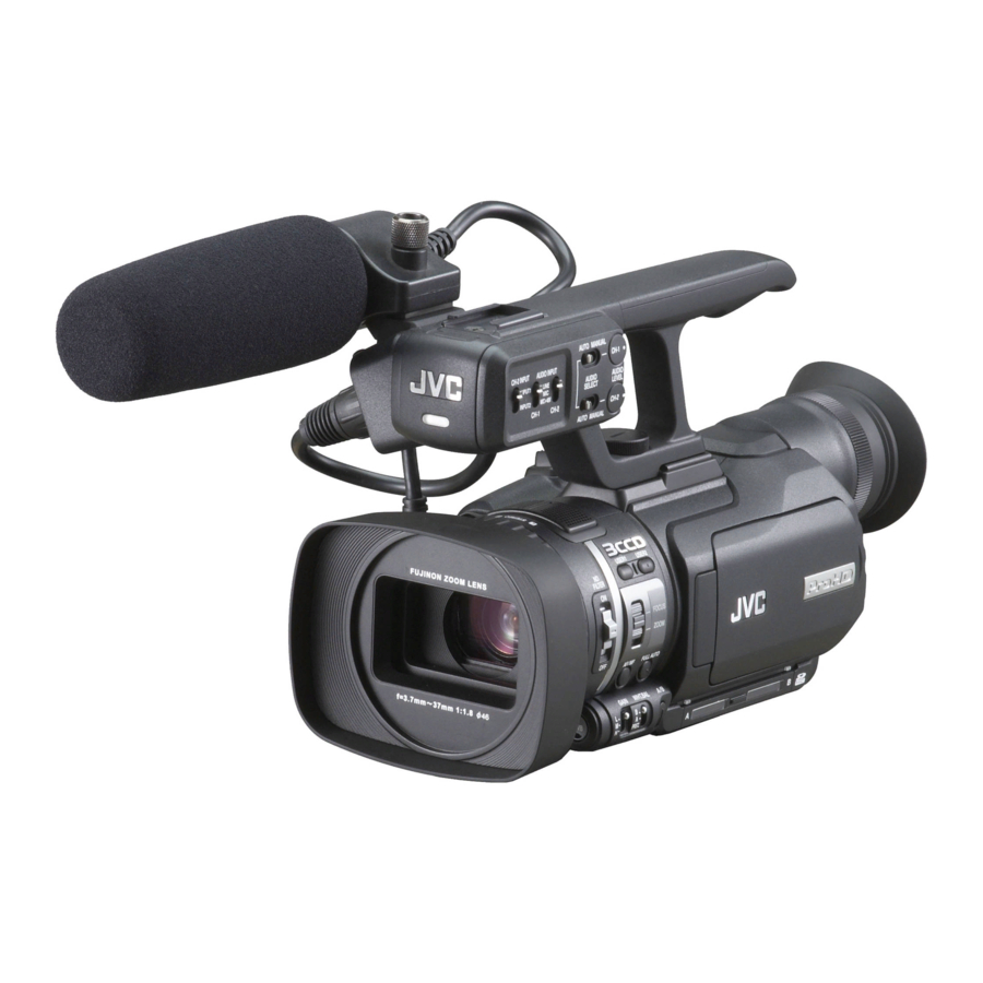
JVC GY-HM100U Manual
Hide thumbs
Also See for GY-HM100U:
- Instructions manual (76 pages) ,
- Quick start manual (49 pages) ,
- Brochure & specs (14 pages)
Table of Contents
Advertisement
Quick Links
Advertisement
Table of Contents

Related Manuals for JVC GY-HM100U


Summary of Contents for JVC GY-HM100U
- Page 1 The JVC Camcorder JVC GY-HM100U Edition Community Television Network...
- Page 2 Community Television Network 2805 S. Industrial Ste. 200 Ann Arbor, MI 48104 734-794-6150 www.a2gov.org/ctn Revised 2/2012...
-
Page 3: Table Of Contents
Table of Contents Field Production Step-By-Step ................2 Lights ........................3 Equipment..................... 3 Lighting Set-Up .................... 6 Tripod........................8 Equipment..................... 8 Tripod Set-Up .................... 10 Camera ......................14 Equipment....................14 Camera Set -Up ..................24 Audio ........................ 26 Equipment....................26 Audio Set-Up ..................... - Page 4 Introduction The JVC Camcorder class is designed to provide you with an understanding of field production, as well as provide you with the operational skills necessary to participate in a production on location as opposed to in a studio. We will cover the camcorder, other portable equipment and how they relate to each other.
-
Page 5: Field Production Step-By-Step
Field Production Step-By-Step Here is a list of the basic steps involved in producing a program utilizing the CTN equipment: Plan your (pre) production. Decide on the who, what, where, why, when and how. Fill out and submit a CTN Production Proposal Form. Decide when you want to begin your production work. -
Page 6: Lights
Lights Where you are doing your production work will dictate whether or not you need to use additional lighting. You will often find using one light, in addition to what already exists at the production location, can greatly enhance the look of your program. This is why scouting a location before hand is so important. - Page 7 The lights have a red power switch located on the back. When the switch is in the on position, you can see a white mark along its edge. Make sure the light is off before plugging it in to an outlet! Spot light, power switch off &...
- Page 8 Stands The stands will allow you to position lights from 2ft. to 8ft. off the ground, however, extreme care must be taken to be sure the light and stand do not fall over. Lights on stands. Diffusion/Gels Diffusion material may be used to reduce or soften the intensity of a light. Sheets of diffusion material can be clipped to the barn doors with clothespins or binder clips.
-
Page 9: Lighting Set-Up
Lighting Set-Up First, figure out how many lights you need and where you will need them. Mapping out your location so you know where existing windows, lights, and outlets are can help. Location sketch. Set up the light stands in the positions you need. Make sure the stands are stable and will not fall over easily. - Page 10 Re-adjust the intensity of light using the focus control. Turn the focus control to flood the light, to cover the area needed. If necessary, adjust the barn doors to control the area of the light spill. Turn the light off and repeat steps 5-9 for the other lights. After adjusting all of the lights, turn them all on and check for shadows, dark areas or other distractions and make additional lighting adjustments as necessary.
-
Page 11: Tripod
Tripod Always , always, always, (get the point) use a tripod whenever, wherever possible. There is just no substitute for a well framed, rock steady picture. It’s one of the bare minimum standards the audience has come to expect. Sometimes it won’t seem as convenient as just “hand holding” the camera, but the Pros will tell you “use a tripod any time you can.”... - Page 12 Tripod The tripod is a three-legged stand, which provides great stability for the camera. Tripod. Mounting Plate The mounting plate can be detached from the tripod, while remaining attached to the camera. Mounting plate.
-
Page 13: Tripod Set-Up
Dolly The dolly is an optional accessory used with the tripod, which supplies wheels allowing the tripod to become somewhat mobile and maneuverable. Dolly. Tripod Set-Up If you are not using a dolly, skip number 1, 2, 4, and 16. Set the dolly in position. - Page 14 Unlock the tripod legs and extend them to the height you want for the camera. Tripod leg with both locks locked, then with both locks unlocked. Attach the tripod to the dolly. Tripod leg seated in dolly. Level the tripod by using the level and adjusting the leg heights. Tripod level.
- Page 15 Check that the legs, the pan lever lock, the tilt wheel lock and the pedestal crank are locked. Tripod pan and tilt locks, pedestal crank and lock. Pan and tilt also have friction knobs Remove the mounting plate from the tripod. Tripod mounting plate.
- Page 16 Loosen the pan and tilt locks so you can freely pan and tilt the camera. Note: Never leave your camera without first tightening the tilt lock. Set the dolly wheels down so you can move when ready. Wheel control flipped down, wheels down, feet up.
-
Page 17: Camera
Camera The camera is the heart of most field productions. Equipment The camera kit comes with a camcorder and a variety of accessories. Camcorder kit. - Page 18 Front View 1. Tally Lamp. When this is set to on the tally lamp lights up in the recording mode 3. Remote camera sensor. Used with the camera remote 4. Auto White Balance Button. Used for adjusting the white balance 5.
- Page 19 LCD Side View 1. Built – In Microphone 2. Lens Cover Switch. Use the lens cover switch to open or close the lens cover 3. Manual Ring. 4. ND Filter Switch. Reduces the amount of incident light to 1/10 5. Gain Switch. For selecting one of the three light sensitivity levels 6.
- Page 20 15/16. User 1/User 2 Button. Used to set special features for each user. 17. CH-1/CH-2 Audio Level Adjustment Knobs. Used to set the audio recording level. CH-1 knob is for audio Channel 1, and CH-2 knob is for audio Channel 2. 18.
- Page 21 LCD Side View (LCD Cover) Beneath the LCD Cover (On the camcorder): 1. LCD Cover. Open the LCD Cover to view the video as it is being shot, and to change menu settings. 3. A/V Out Terminal. Use to connect camcorder to a television or analog audio capture device. 4.
- Page 22 On the LCD Cover: 10. REC Button. Press to start recording. 12. INDEX Button. In shooting mode: Press once to display the remaining space on the memory card. Press a second time to display remaining battery power. Press again to display the camera output. In playback mode: Press to display playback index or date search modes.
- Page 23 Rear: 1. Iris Button. Use to set the aperture (iris) manually. 2. Shutter Button. Use to set the shutter speed manually. 3. AE ± Button. Use to set the exposure manually. 4. Adjustment/Volume Knob. ADJ: Use to set the aperture (iris), shutter speed, and exposure, after pressing the appropriate button above it.
- Page 24 Grip Belt Side: 14. Power Switch. Turns the camcorder on or off, and switches between video mode and still picture mode. 16. Headphone Jack. Connect headphones to this jack to monitor the incoming audio during recording, and to monitor the recorded audio during playback. 17.
- Page 25 Accessories Camcorder batteries & Camcorder manual. Manual – a copy of the JVC GY-HM100U camcorder manual. Battery Packs - Provide the DC power when AC (wall outlet) power is not available. The batteries are rechargeable. Charging Time Approx, 3hrs 40 Minutes...
- Page 26 AC adapter and DC input cable. Power Adapter & DC Coupler - supply power from a wall outlet to the camcorder. In addition, the Power Adapter serves the dual purpose of charging a battery pack. Video cable & Headphones. Video / USB Cable – used to connect the camcorder to a VCR, television, computer (downloading files from SD Card) or other monitor and/or audio equipment .
-
Page 27: Camera Set -Up
Omni microphone, mic cable, and white balance card. Omni Microphone & Mic Cable – used when the camera’s built-in microphone would produce unacceptable or less than desirable audio results, particularly in commentary type or interview situations. White Balance Card – used to calibrate the camera for correct and consistent color, under those conditions. - Page 28 When ready, press the REC button to begin recording. Cue the talent to begin. When the talent finishes, press the REC button to stop recording.
-
Page 29: Audio
Audio Equipment There is an omni hand-held microphone provided with the camcorder kit, but there may be times when neither the omni nor the camera mic are sufficient for your production needs. Microphones There are 4 other types of microphones available for use: Cardioid Mics &... - Page 30 Tabletop Stand, Floor Stand Tabletop stands – can be used to position mics “on camera” on a table or desk. Floor stands - can also be used to position mics “on camera”. When using Lavaliers, the mics will be clipped to each person appearing on the program and there are several tips for attaching these mics to people: Clip 'em.
- Page 31 Looping the wire, top view Loop the wire. This helps to keep the wire hidden, even when the talent moves around a lot in his chair. Simply press the clip open, pull the wire into the clip, and pull the wire taut (see illustration). Most Important.
- Page 32 Audio Mixer The Shure Audio Mixer is composed of four (4) input channels and a MASTER output channel. Shure audio mixer, front. Input Channels Each input channel has the channel number below the level controls. LO CUT – reduces low frequency sounds (wind noise) when set to IN. Input Level Control Dial –...
- Page 33 Shure audio mixer, back. VU RANGE – should be set to +8. SIMPLEX – provides “phantom” power for microphones that require it. Should be set to OFF when using microphones which are self-powered. GROUND, 2 & 3 (red knobs) – not used. LINE / MIC (output) –...
-
Page 34: Audio Set-Up
Audio Set-Up Position the mics where they will be used. If necessary, insert batteries into the mics. Connect each mic to a mic cable. Set-up the mixer near the camera and plug into the nearest outlet. Connect each mic cable to an input on the mixer. When doing this, you should always try to hook up the mics in order from left to right when facing the set.