
Related Manuals for NAPCO iSecure


Summary of Contents for NAPCO iSecure
- Page 1 WI2240ALF 6/21 © NAPCO 2021 Napco iSecure Security System All technical manuals are available in PDF format at tech.napcosecurity.com...
- Page 2 Windows are registered trademarks of the Microsoft publication and to make changes from time to time in the content hereof without obligation of Napco to notify any person of such revi- Corporation. sion or changes. All other trademarks cited in this manual and all other © Napco...
-
Page 3: Table Of Contents
Programming: Takeover Modules ....54 Go-Anywhere Hub Rear Access Descrip- tions ............ 11 User Codes ..........55 2. Install the Keypad ........12 Other iSecure Cloud Web Portal Screens ............56 Configure the IBR-TOUCH-WL 7" Touchscreen ........13 3. Install Motion Sensors ......15 Troubleshooting .......... -
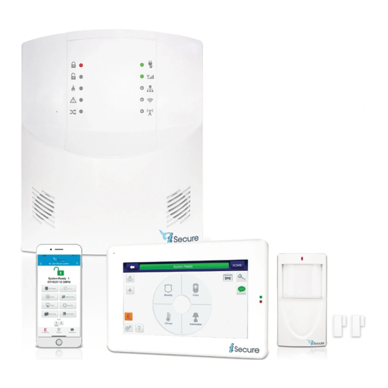
Page 4: Overview
• SLE-ANTEXT50 50' Remote Antenna Kit the instructions for the peripherals and devices included with • SLE-ANTEXT75 75' Remote Antenna Kit the iSecure kit or for any additional devices purchased, as re- • SLE-ANTEXT100 100' Remote Antenna Kit quired. All wireless devices, including Z-Wave devices, must be signal tested with all enclosure covers fully See page 73 for ordering and additional information. -
Page 5: New User Pre-Installation And Configuration Steps
• Tap Configure Remote Logins > New User Register the Hub, Purchase a Service Plan, and Down- • In the Username field, enter the Radio ID ("iSecure LTE ID#") load Device and Central Station Data into the Hub located on the card (OI404LF) With the Hub powered, download the iBridge app with a PC, laptop •... -
Page 6: Dealer Account Activation & Programming
Simply add extra devices or make changes to the existing devices as needed. To log into the iSecure Cloud Web Portal, proceed as follows: 1. Open your browser and go to the iSecure Cloud Web Por- tal at www.iSecureByNapco.com. An initial login screen appears:... - Page 7 Any changes to the Master Security Code requires that you exit and re-enter the iSecure Cloud Web Portal. System 5. Click Log Out to exit, then log back in to the iSecure Cloud Information Web Portal (www.iSecureByNapco.com) as described in step 1 and step 2.
-
Page 8: Central Station Cs Reporting Screen
March 15 date. dio #, enable the Central Station Reporting radio button. The iSecure Cloud Web Portal also has the ability to send Note: To ensure that the iSecure Cloud Web Portal has the emails and text messages to dealers and/or customers latest configuration data stored in the Hub, click the Upload (only available if supported by your service plan). - Page 9 PC board circuitry. Upload Radio Status (button) Checkins Click to ensure that the iSecure Cloud Web Portal has the The Check-in log displays radio transmissions that are latest configuration data stored in the Hub. This is rarely not routed to the central station.
-
Page 10: Install The Go-Anywhere Hub
2. Using #8 screws appropriate for the mounting surface, install the top two screws into mounting surface. Note: Do the iSecure Kits 1, 2 and 3 each require a router When mounting to hollow drywall or similar surface, we with Wi-Fi connected to the Internet at the installation... -
Page 11: Go-Anywhere Hub Rear Access Descriptions
Note: The rear terminals, headers and sockets are not accessible after wall mounting. TERMINAL DESCRIPTIONS Configure all inputs and outputs using the iSecure Cloud Web Portal at www.iSecureByNapco.com. Located at the bottom of the Go-Anywhere Smart Hub PC board, the 11 terminals are described as follows: Z7 (‒):... -
Page 12: Install The Keypad
Program the Go-Anywhere Hub by entering the "RF ID #" (printed on the sticker to strong pressure on the LCD surface. In located on the back of the keypad) into the iSecure Cloud Web Portal, as follows: addition, the polarizer used on the LCD Click Wireless Modules >... -
Page 13: Configure The Ibr-Touch-Wl 7" Touchscreen
IBR-TOUCH- ble an additional keypad in iSecure Hub programming. WL by pressing and holding the • First register your Hub and purchase an iSecure Service small button on the right side for Plan at www.NapcoComNet.com, 10 seconds (the touchscreen will •... - Page 14 When finished, tap Save & Next>>. The IBR-TOUCH-WL will automatically attempt to As shown in the image below, the system will then connect, through the "cloud", to the NAPCO iSe- automatically try to connect the IBR-TOUCH-WL cure account. Enter your administrator account locally through Wi-Fi, provided the Hub is con- User ID and Password and tap Finish.
-
Page 15: Install Motion Sensors
The ISEC-MOTION is an advanced PIR sensor designed for use 1. To open the case, insert a small screwdriver in the slot at the with Napco's wireless receivers. The unit is powered by two sup- bottom and push up slightly. Remove the front cover. -
Page 16: Install Glass-Break Sensors
The ISEC-GLASSBREAK is an advanced wireless acoustic ence purposes in this text, the unit will be considered oriented glass-break detector for use with the iSecure Go-Anywhere with the antenna at the right, as shown above. Smart Hub and receivers. Each transmitter has a unique RF The detector mounts with two #6 screws (supplied). - Page 17 (do not use detector with heavy or lined drapes). If the detector is mounted on the same wall as the glass, point the tester at the opposite wall. Napco iSecure Security System All technical manuals are available in PDF format at tech.napcosecurity.com...
-
Page 18: Install Window / Door Transmitters
The ISEC-DW-XMITTER is a low profile window/door Front Cover. If mounting the Magnet with double- transmitter designed for use in Napco iSecure wireless sided tape, the Magnet Housing tabs may optionally systems. Used with the supplied magnet, the transmitter be removed--use a utility knife only--do not bend or functions as a window/door sensor. -
Page 19: Install Smoke Sensors
DL123A, Varta/Power One Model CR123A or Pana- detector with built-in supervised digitally-coded radio sonic CR123A NEGATIVE END FIRST in its battery transmitter. It is compatible with Napco’s iSecure-series compartment, observing correct polarity (see page system that monitor alarms, restores, low battery and 21). - Page 20 Press and hold the Test button for about 5 seconds and release when the sounder turns TEST BUTTON on. While holding the but- continued Napco iSecure Security System All technical manuals are available in PDF format at tech.napcosecurity.com...
- Page 21 Caution: Changes or modifications not expressly approved by manufacturer could void the user's authority to operate the equipment. • See page 48 for full programming information continued Napco iSecure Security System All technical manuals are available in PDF format at tech.napcosecurity.com...
- Page 22 In family living units with more than one sleeping area, a smoke A smoke detector should be alarm should be provided for located on each story each separate sleeping area. Napco iSecure Security System All technical manuals are available in PDF format at tech.napcosecurity.com...
-
Page 23: Install Heat Sensors
Rate of Rise. It is compatible with ID# on the label must be accurately recorded in order to the NAPCO iSecure-series supervised security system. map the transmitter into the system (see Step 7). Protected coverage area is 50' x 50' with a ten foot ceiling height. - Page 24 A TAMPER ZONE TROUBLE WILL RESULT WHEN THE BATTERIES ARE REPLACED. • See page 49 for full programming information MOUNTING TEMPLATE NSURE THIS BOX IS INCH INCH Napco iSecure Security System All technical manuals are available in PDF format at tech.napcosecurity.com...
-
Page 25: Install Carbon Monoxide Sensors
LIVING removal without a ROOM tool BEDROOM 5. Install mounting plate. Use two screws and hardware appropriate for the mounting surface to secure the continued Napco iSecure Security System All technical manuals are available in PDF format at tech.napcosecurity.com... - Page 26 5 minutes. • Red LED blinks once every 5 seconds; sounder chirp eve- ry 45 seconds = CO Trouble / Calibration. (Note: continued Napco iSecure Security System All technical manuals are available in PDF format at tech.napcosecurity.com...
- Page 27 BASEMENT Indicates required CO detector Indicates optional CO detector if door is not provided between Living BASEMENT and Recreation rooms. continued Napco iSecure Security System All technical manuals are available in PDF format at tech.napcosecurity.com...
- Page 28 • Read these installation instructions in their entirety be- exhaust fans fore installing the ISEC-CARBON MON detector. Leave these instructions with the owner/user of the detector. continued Napco iSecure Security System All technical manuals are available in PDF format at tech.napcosecurity.com...
- Page 29 CO detectors are not a substi- tute for designated life safety devices. Napco does not war- rant or imply in any way that a CO detector will protect lives from CO poisoning. These detectors should only be consid- ered as an integral part of a comprehensive safety program.
-
Page 30: Install Panic Button
The ISEC-PANIC Panic is an single function pendant / key- LED lights when unit is transmitting chain transmitter compatible with the NAPCO iSecure security Plastic Bead Neck Chain system. The ISEC-PANIC serves as an emergency device for use as a police panic and/or auxiliary emergency transmitter. -
Page 31: Install Keyfobs
10. Install Keyfobs The ISEC-KEYFOB is a multifunction pendant/keychain trans- BATTERY REPLACEMENT mitter compatible with Napco iSecure-Series wireless systems. 1. Remove the keyring from the keyfob case. It serves as an area arm/disarm device with two auxiliary func- 2. Carefully insert the edge of a small coin in the notch locat-... -
Page 32: Install Siren
(magnet removed), the siren reports a tamper trouble to the Go-Anywhere Hub. In addition, pressing the keypad RESET button sends an updated status from the ISEC-WL-SIREN to the Go-Anywhere Smart Hub. Napco iSecure Security System All technical manuals are available in PDF format at... -
Page 33: Install Takeover Module
Make the run as short and direct as possible, without them into iSecure system wireless zones. Up to 4 ISEC-WL- any sharp bends in the wire. MODULEs are allowed with each Go-Anywhere Smart Hub. - Page 34 • CO (middle two pins): Selected zone reports as a carbon monoxide (model ISEC-CARBON MON) transmitter. • BURG (lower two pins): Selected zone reports as a Bur- glary window / door transmitter (model ISEC-DW- continued Napco iSecure Security System All technical manuals are available in PDF format at tech.napcosecurity.com...
- Page 35 Wiring example of a Wiring example of a burglary Conventional 4-Wire Carbon Monoxide device; in this example, a Smoke Detector Detector wired door / window contact Napco iSecure Security System All technical manuals are available in PDF format at tech.napcosecurity.com...
-
Page 36: Install The Isec-2Wf-Mod
2WF-MOD permits the use of existing compatible 2-Wire smoke detectors (see list of compatible smoke detectors, be- FIRE PR+ low), and all existing wiring to be used with your iSecure secu- Z8 (‒) rity system. The ISEC-2WF-MOD requires 15mA standby current. The ISEC-2WF-MOD signals an alarm when the smoke detector ‒... - Page 37 10, step 3. Remove all A/C and battery power and install the ISEC-2WF -MOD into the iSecure Hub main PCB as follows: 1. Insert the plastic Standoff into the bottom of the ISEC-2WF-MOD (Fig.
-
Page 38: Install The Isec-Wifi
Important: Handle this wire with care; do not twist, create sharp bends or apply excessive force. Fig. 2: Arrows show six (6) screws securing the motherboard. The Top Antenna, is also shown Napco iSecure Security System All technical manuals are available in PDF format at tech.napcosecurity.com... - Page 39 Fig. 7: Align and insert ISEC-WIFI (PC Board) ISEC-WIFI (see Fig. 5). P R O G R A M M I N G After the ISEC-WIFI module is installed, program the Go- Anywhere Hub using the iSecure Cloud Web Portal: 1. Log into iSecure...
-
Page 40: Install The Isec-Zwave
2 minutes for all devices to fully power before proceed- 3. Carefully align the two Standoffs with their two holes, ing. For additional programming information, see OI414. Napco iSecure Security System All technical manuals are available in PDF format at tech.napcosecurity.com... -
Page 41: Install The Isec-Extant-Kit (Optional)
This Bracket assembly, pictured in Fig. 1, provides an alternate SMA con- nection to the LTE radio, allowing the use of Napco SLE- ANTEXT antenna kits. The remote-mounted antenna is a du- al-wideband, indoor/outdoor LTE antenna that significantly... - Page 42 Hub by plugging in the AC transformer. Test system operation. 11. For strain relief, secure the cable to the PCB by in- serting the zip tie into the PCB hole shown in Fig. 8. Napco iSecure Security System All technical manuals are available in PDF format at tech.napcosecurity.com...
-
Page 43: Go-Anywhere Smart Hub Icons
• Flashing: 900MHZ peripheral download 9 blinks: Wi-Fi no serial data • response Status 10 blinks: Wi-Fi security authen- • Off: No transmissions • tication failed Napco iSecure Security System All technical manuals are available in PDF format at tech.napcosecurity.com... -
Page 44: Programming: Keypads / Touchscreens
Note: A reading of 3 or (removal from rear back (button less indicates reception may be erratic; case or from wall) presses, etc.) relocate the keypad closer to the Hub. Napco iSecure Security System All technical manuals are available in PDF format at tech.napcosecurity.com... -
Page 45: Programming: Motion Sensors
1-10 (10 being the strongest). Note: A reading of 3 or less indicates reception may be erratic; relocate the sensor closer to the Hub. Napco iSecure Security System All technical manuals are available in PDF format at tech.napcosecurity.com... -
Page 46: Programming: Glass-Break Sensors
1-10 (10 being the strongest). Note: A reading of 3 or less indicates reception may be erratic; relocate the sensor closer to the Hub. Napco iSecure Security System All technical manuals are available in PDF format at tech.napcosecurity.com... -
Page 47: Programming: Window / Door Transmitters
ID # for the tion you wish to appear Select "Door ENABLE REPORTING on the keypad display Window". device Check to enable cen- tral station reporting Napco iSecure Security System All technical manuals are available in PDF format at tech.napcosecurity.com... -
Page 48: Programming: Smoke Sensors
1-10 (10 being the strongest). Note: A reading of 3 or less indicates reception may be erratic; relocate the sensor closer to the Hub. Napco iSecure Security System All technical manuals are available in PDF format at tech.napcosecurity.com... -
Page 49: Programming: Heat Sensors
Relative intensity of the last transmission, on a scale of 1-10 (10 being the strongest). Note: A reading of 3 or less indicates re- ception may be erratic; relocate the sensor closer to the Hub. Napco iSecure Security System All technical manuals are available in PDF format at tech.napcosecurity.com... -
Page 50: Programming: Carbon Monoxide Sensors
Relative intensity of the last transmission, on a scale of 1-10 (10 being the strongest). Note: A reading of 3 or less indicates re- ception may be erratic; relocate the sensor closer to the Hub. Napco iSecure Security System All technical manuals are available in PDF format at tech.napcosecurity.com... -
Page 51: Programming: Panic Buttons
Select "Panic sor ID # for REPORTING on the keypad display Button". the device Check to enable cen- tral station reporting Napco iSecure Security System All technical manuals are available in PDF format at tech.napcosecurity.com... -
Page 52: Programming: Keyfobs
Default = 1. See the key- sensor ID # for you wish to deactivate pad Operating Guide for the device your KeyFob the definition of "Area". Napco iSecure Security System All technical manuals are available in PDF format at tech.napcosecurity.com... -
Page 53: Programming: Sirens
ID # for erratic; relocate the sen- siren. display the device sor closer to the Hub. Napco iSecure Security System All technical manuals are available in PDF format at tech.napcosecurity.com... -
Page 54: Programming: Takeover Modules
ID # inactive; relocate the module closer by the assigned wireless zone . for the device learn the unit. to the Hub (or vice versa). Napco iSecure Security System All technical manuals are available in PDF format at tech.napcosecurity.com... -
Page 55: User Codes
Add new User Codes or erase / change / review existing User Codes, as follows: 1. Go to www.iSecureByNapco.com and log into your iSecure account. 2. Click User Codes. The USER CODES screen appears. Note: With up to 96 User Codes allowed, each one is assigned a "USER#"... -
Page 56: Other Isecure Cloud Web Portal Screens
Separate delays that let you exit and enter your premises without must match the code at the corresponding Hub. Note: All key- setting off an alarm when the system is armed. The iSecure sys- pad programming must be performed at the keypad addressed as tem has three programmable Entry Delay times available: 30, 45 Keypad # 1. - Page 57 • With the ISEC-WL-KEYPAD LCD keypad, use the key- time (for LTE and Voice Prompts only). The iSecure Cloud pad "Local Functions" (perform the steps in the "Keypad Web Portal first compares the original account program- Attributes"...
- Page 58 Displays the USER ID, NAME, EMAIL address of those in the iSecure Cloud Web who can log into the iSecure Cloud Web Portal. MASTER Portal overwrites is checked for those users authorized to make all changes ALL configuration data in to the account without restrictions.
- Page 59 Creates a copy of the current iSecure Configuration data • INTEGRAL KEYPAD (reserved for future use) already in the iSecure Cloud Web Portal and retains it in • RF RECEIVERS1 refers to the integral Hub 319MHz the Cloud Web Portal for later retrieval, if needed.
-
Page 60: Troubleshooting
Troubleshooting Your iSecure system will warn you of any problems by flashing a yellow LED next to the triangle "!" (system trouble) icon located on the face of the Go- Anywhere Smart Hub (and with keypad indications). Here are some common warnings and recommended solutions: "ZONES FAULTED"... -
Page 61: Cold Start, Test And Reset Processes
Cold Start, Test and Reset Processes Your iSecure Go-Anywhere Smart Hub and 900 MHz Keypads, Siren and Take Over module can be reset back to their original "default" conditions, i.e. the state each was in when they first left the factory. Proceed as follows: Go-Anywhere Hub Factory Reset (Cold Start) The Go-Anywhere Smart Hub can be reset back to its original "default"... -
Page 62: Common Error Codes / Troubles
E60-05 -- Radio Poll or Check in failure (RF only) dition, i.e. the state it was in when it left the factory). Call installing company for service. Napco iSecure Security System All technical manuals are available in PDF format at tech.napcosecurity.com... -
Page 63: Isec-Wl-Keypad "Local Functions
Cloud Web Portal when the keypad was added into the • 36 - Signal strength received by the keypad expressed in dBm system. Up to 6 keypads may be installed in each iSecure units (signal level relative to 1 milliwatt), provided for those... - Page 64 If the system is experiencing 900Mhz communication issues and The first to be displayed is the keypad RF ID number: there is the belief that a nearby iSecure system might be interfering • rF id - The numbers displayed are identical to the RF ID num- with the system to be installed, the ISEC-WL-KEYPAD can be used as a "scanner"...
-
Page 65: Isec-Wl-Touch "System Diagnostics" And "Autoenroll
AutoEnroll This feature is a quick and easy way to enroll wireless devices into your iSecure system. Before you begin, remove the bat- tery from the wireless device. With the unpowered wireless device physically "in hand", and with its battery within reach... -
Page 66: Keypad Dealer Function Menu
This eliminates the need of returning to the keypad play to scroll through multiple system troubles. to visually check after each attempt. Press RESET to restore normal operation (arming the system auto- Napco iSecure Security System All technical manuals are available in PDF format at tech.napcosecurity.com... - Page 67 1 to 4 hours, as above, or auto-arming may be canceled by arming and disarming the Go- Anywhere Hub. Napco iSecure Security System All technical manuals are available in PDF format at tech.napcosecurity.com...
-
Page 68: Ibr-Touch-Wl Dealer Settings Menu
Wi-Fi network and iBridge radio, and option- the IBR-TOUCH-WL and customer's router. Includes ally the NAPCO StarLink account(s). See page 13 for step- discovery and ports established during the initial hand- by-step instructions to help guide you through the Wizard. - Page 69 Note: The update file scribed above. Note: All wireless cameras in the must be placed in a folder named "napco" (case system must be unlocked before using this feature sensitive) located in the top root directory.
- Page 70 "ISEE Series Cameras" is selected in the Setup Wiz- Launcher ard (see page 13 for more information about the Setup Wizard). (Reserved for NAPCO use only) Camera List Camera Auto Discovery: Check to allow the Home touchscreen to automatically attempt to capture and...
- Page 71 "E" (Emergency) button will appear on the Home Screen, it will be disabled and the message, "Permission Denied. Please Contact Dealer." will appear when tapped. Change Login URL Not Used; do not change this selection. Napco iSecure Security System All technical manuals are available in PDF format at tech.napcosecurity.com...
-
Page 72: Standby-Battery Calculation Worksheet
*Actual standby time will vary with Kit, system components and network use. For components included in each kit and other details, see Ordering Information on page 73. **Maximum bell current is 300mA (with integral siren disabled, no strobes, and no 2-wire smoke detectors with integral sounders) iSecure Kit 1 and Kit 2 only, if added. iSecure Kit 1, if added. -
Page 73: Ordering Information
An advanced Commercial/Residential network, "A" use the AT&T network. wireless acoustic glass-break sensor designed for use with Napco iSecure series RECV wireless receivers. Equipped with a combination normally Napco iSecure Security System All technical manuals are available in PDF format at... - Page 74 • ISEC-MOTION Passive Infrared Motion Sen- sor: An advanced PIR sensor designed for use with Napco's iSecure RECV series wireless re- ceivers. The ISEC-MOTION is powered by two supplied 3-volt lithium batteries (estimated battery life 3 years). When battery voltage drops below normal, a low-battery report will be sent to the re- ceiver.
-
Page 75: Isec-Wl-Siren Wireless Siren Mounting
Magnet Screws (2) Slide Screw (Use with battery (Use with battery powered units only) powered units only) 7/16" NSURE THIS BOX IS INCH INCH Magnet 1-5/8" Napco iSecure Security System All technical manuals are available in PDF format at tech.napcosecurity.com... - Page 76 Notes Napco iSecure Security System All technical manuals are available in PDF format at tech.napcosecurity.com...
- Page 77 Magnet Screws (2) Slide Screw (Use with battery (Use with battery powered units only) powered units only) 7/16" NSURE THIS BOX IS INCH INCH Magnet 1-5/8" Napco iSecure Security System All technical manuals are available in PDF format at tech.napcosecurity.com...
-
Page 78: Isec-Wl-Module Takeover Module Wiring Diagram
ISEC-WL-MODULE Takeover Module Wiring Diagram Napco iSecure Security System All technical manuals are available in PDF format at tech.napcosecurity.com... -
Page 79: Isecure Hub Wiring Diagram
S e c u r e H u b W i r i n g D i a g r a m LA3550A3 Napco iSecure Security System All technical manuals are available in PDF format at tech.napcosecurity.com... -
Page 80: Napco Limited Warranty
FCC EXPOSURE GUIDE The iSecure internal LTE radio has been tested to FCC Section 15.247(i) and requires a minimum spacing of 7.87" from the user to comply with both the Occupational/Controlled Exposure and the General Population/Uncontrolled Exposure require- ments of FCC Part 1.1310.