
Related Manuals for Rinnai Ember 600


Summary of Contents for Rinnai Ember 600
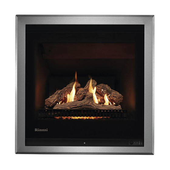
- Page 1 Models: RDV600N / RDV600L RDV700N / RDV700L Ember series gas fireplaces Installation guide...
- Page 2 Important Appliance must be installed with a Rinnai approved flue system. This appliance shall be installed in accordance with: - Manufacturer’s installation instructions Current: - AS/NZS 5601 Gas Installations - AS/NZS 5263 Gas Appliances General Requirements - AS/NZS 3000 Electrical Standards...
-
Page 3: Table Of Contents
Contents Before you start ............4 Specification ............5 Dimensions ............6 Gas and electrical supply ........8 Enclosure dimensions ..........9 Clearances from combustibles ......10 TV installation ............12 Ember masonry installation overview ....14 Ember mock chimney installation overview ..16 Installing the zero clearance frame.......18 Attaching the flexi flues to the spigot plate ...19 Burn media installation .........20 Removing the burner box glass panel ....21... -
Page 4: Before You Start
Failure to follow these instructions could cause a malfunction of the appliance. This could result in serious injury and/or property damage. Ensure the flue termination will meet the required flue clearances as shown in AS/NZS 5601.1 before installation. Item Masonry installation Mock chimney installation Ember 600 Ember 700 Ember 600 Ember 700 ENGINE ... -
Page 5: Specification
A direct vent inbuilt gas fireplace with a glass front and convection fan, pushing warm air from the top of the appliance. Operated by a simple infra-red remote or by the Rinnai Wi-Fi app that allows full thermostatic control, as well as other features such as timers. Different burn media and frame options are available. -
Page 6: Dimensions
Ember 600 with 4-sided frame (mock chimney installations) 535 mm Viewable glass dimensions, same for both 600 models Ember 600 with 3-sided frame (masonry installations or mock chimney installations with a hearth) infill panel 6 | Ember Installation Guide: 12890-F 06-21... - Page 7 Ember 700 with 4-sided frame (mock chimney installations) 638 mm Viewable glass dimensions, same for both 700 models Ember 700 with 3-sided frame (masonry installations or mock chimney installations with a hearth) infill panel masonry frame 92.5 92.5 Ember Installation Guide: 12890-F 06-21 | 7...
-
Page 8: Gas And Electrical Supply
If the supply cord is damaged, it must be replaced by a licensed tradesperson. This must be a genuine replacement part available from Rinnai. * Consult a qualified electrician if direct wiring is required as it must comply with AS/NZS 5601 and AS/NZS 3000 and other relevant... -
Page 9: Enclosure Dimensions
Please note If installing the Rinnai Ember into a purpose built chimney breast or chase, which is not open to the roof space of the building, you will need to add cavity vents. Refer p. 32-33... -
Page 10: Clearances From Combustibles
Clearances from combustibles The clearances listed below, measured from the edge of the glass, are minimum clearances unless otherwise stated. While the heater is operating The appliance must not be installed where curtains or other combustible materials could come into contact with the heater. The 400 mm side clearance includes side walls. - Page 11 The 4-sided frame is shown as this is the frame used in mock chimney installations, which typically have mantels and surrounds made of combustible material. The 4-sided frame sits approximately 26 mm below the engine, refer dimension diagrams. Ember 600 4-sided frame 1340 Minimum above fire Distance off the floor could be 0-400 mm.
-
Page 12: Tv Installation
TV installation with the TV manufacturer—some have warranty conditions that state a TV is not to be installed above a fireplace. Rinnai does not accept any responsibility for damage to a TV resulting from the use of this information. 400 mm... - Page 13 Installation Installation, servicing and repair shall be carried out only by authorised personnel. Ember Installation Guide: 12890-F 06-21 | 13...
-
Page 14: Ember Masonry Installation Overview
Ember masonry installation overview Modify the enclosure Ensure the enclosure meets the requirements set out on p. 9. Gas and electrical connections Prepare gas and electrical connections, refer p. 8. Connect flexi to flue terminal Stretch out the flexi to the required length and attach to the flue terminal using the clamps provided. - Page 15 Make sure the chimney cap is Check the size of the chimney before weathertight. Flexi flue also needs to be doing anything. It needs to be at least secured to the flue cowl using the clamps 200 x 200 mm for the colinear flexi flue to provided—these need to be riveted/ fit down.
-
Page 16: Ember Mock Chimney Installation Overview
Ember mock chimney installation overview Modify the enclosure Ensure the enclosure meets the requirements set out on p. 9. Gas and electrical connections Prepare gas and electrical connections, refer p. 8. Install the zero clearance frame Install the zero clearance frame into the enclosure and fix in place with the screws provided. This frame is critical and must be installed as it automatically gives the required clearances to combustibles. - Page 17 Self-supporting coaxial flue; inner Flue cowl needs to a 500 mm clearance from the Ø 100 mm, outer Ø 170 mm. Requires nearest ridge line of the roof. In this instance the 10 mm clearance to a combustible flue pipe has been painted to match the roof. surface.
-
Page 18: Installing The Zero Clearance Frame
Installing the zero clearance frame (R2450) For mock chimney installations the zero clearance frame is a mandatory requirement to ensure a safe installation for the homeowner. The zero clearance frame is fitted prior to final cladding. It is a universal frame, designed for different opening sizes. For installation refer to the detailed instructions provided with the zero clearance frame kit. -
Page 19: Attaching The Flexi Flues To The Spigot Plate
Attaching the flexi flues to the spigot plate The flexi flues need to be securely fixed to the engine spigot plate using the clamps provided, and the clamps need to be screwed in place. To do this the spigot plate needs to be temporarily removed from the engine—undo the two front screws holding it in place. -
Page 20: Burn Media Installation
Ember 600/700 burn media sets - they are different and can’t be interchanged The Ember 600 and 700 burn media sets are different. The Ember 600 stone set has six less stones and the log set is narrower and shorter—ensure you have the correct kit before starting. -
Page 21: Removing The Burner Box Glass Panel
Removing the burner box glass panel Before adding the burn media, the burner box glass panel needs to be removed. There are two screws on each side (circled on the image to the right). DO NOT undo the screws holding the metal L brackets in place, as these hold the glass in place. -
Page 22: Log Set Installation
While the log set for the Ember 600 and 700 are different (Ember 600 is smaller), the installation steps are the same—the 700 has been used in these instructions. - Page 23 Step 1: Back log Place the back log onto the two log location brackets at the back of the burner. The charred side faces to the front. Step 2: Adding the granules and rockwool Place, DO NOT POUR, the granules, ensuring even coverage around the burner ports (so as not to cause blockages).
-
Page 24: Stone Set Installation
While the stone sets for the Ember 600 and 700 are different (Ember 600 has six less stones), the installation steps are the same. Refer to p. 20 for the correct installation order. - Page 25 Step 1: Back row of stones Place the back row of stones as shown. Ember 600 Ember 700 Step 2: Middle row of stones Place the middle row of stones BETWEEN the burner ports as shown. Ember 600 Ember 700 Step 3: Front row of stones Add the front row of stones inside the grill.
-
Page 26: Commissioning
Commissioning The gas pressures must be checked against those printed on the data plate of the appliance. The pressures are factory set and may not require adjustment. When checking the operating pressures the combustion chamber glass must be on. The commissioning sheet, and a 19 mm small spanner for the gas connection, is located in a plastic pouch inside the unit on top of the PCB cover. -
Page 27: Installing The Frame
Installing the frame Easy four stage process, which will be the same regardless of frame type, for example 3-sided frame, 4-sided frame, or the 700 masonry frame. U-shaped fixings (1 of 3) for screwing the frame in place Frame slots Frame hanger (1 of 2) CAT5 connection Lower screw position... -
Page 28: Test Operation And Lighting Sequence
Abnormal flame pattern If the appliance cannot be made to perform correctly please contact Rinnai. Installation checklist and customer handover Complete the installation checklist in the customer operation guide, and make sure you leave the guide with the customer. Take the time to explain... -
Page 29: Wiring Diagram
Wiring diagram (part of commissioning) gr/y gr/y AC 230-240V gr/y 1 2 3 4 5 6 7 8 r bl 1 2 3 1 2 3 4 5 6 7 8 9 13 12 11 10 9 8 7 6 5 4 3 2 1 gr/y 12 11 10 9 8 7 6 5 4 3 2 1 4 3 2 1... -
Page 30: Ember Flueing
The Ember must be installed with an approved flue system, approved components are shown in this guide. General flueing guidelines Flue clearance to combustibles Flueing for the Rinnai Ember, depending on the installation is comprised of three main components: Coaxial flue... - Page 31 Supporting the flue is usually completed during the framing stage with flue supports or straps within the cavity. Wall straps have been included in the Rinnai vertical flue kits. Elbow straps are also available as a separate component to prevent excess weight on the flue elbow.
-
Page 32: Flueing Options
400 mm. Check clearances before installation. If installing the Rinnai Ember into a purpose built chimney breast or chase, which is not open to the roof space of the building, you will need to add cavity vents. - Page 33 600 mm due to the heat from the colinear flexi flues. If installing the Rinnai Ember into a purpose built chimney breast or chase, which is not open to the roof space of the building, you will need to add cavity vents.
- Page 34 Flueing options Mock chimney - vertical terminations Flue components Max. 2 m Roof cowl (R3651) Flue pipe(s) or flue extension Flue elbow 45 ° (R3642) Maximum number of 45° bends is two. Ember adaptor (R3653) Refer p. 30 for clearance to combustible information for the Ember adaptor.
- Page 35 Flueing options Non-combustible opening only - vertical termination Flue components Masonry chimney flexi vertical flue kit (R3652) Extends out to 8 m. Actual chimney size needs to be at least 200 x 200 mm for the flexi flues to fit down the chimney.
- Page 36 Flueing options Non-combustible opening only - horizontal termination Flue components Ember adaptor (R3653) 400 mm Stretches out to 1.2 m. Masonry horizontal flue box (R2449) Horizontal wall terminal (R3650) Photo of an assembled masonry horizontal flue box and wall terminal 36 | Ember Installation Guide: 12890-F 06-21...
-
Page 37: Flue Kits And Components
Flue kits and components Mock chimney vertical flue kit 3.6 m Mock chimney horizontal flue kit Code: R3665 Code: R3654 Coaxial vertical flue kit Coaxial horizontal flue kit that attaches to the that attaches to the Ember Ember Adaptor. Adaptor. If longer flueing is required order additional flue Kit includes;... - Page 38 Flue kits and components Ember flue adaptor (R3653) Flue pipes Roof cowl (R3651) Colinear to coaxial adaptor. 150 mm: R3630 Aluminium flue terminal Contains; adaptor, locating 230 mm: R3631 required for all vertical flue plate (455 x 455 mm), Ø 75 300 mm: R3632 installations—part of all vertical...
- Page 39 Horizontal wall terminal Horizontal flashing kit Elbow flue strap (R3644) (R3650) (R3646) Flue support for elbows and Aluminium flue terminal Flashing components used offsets. required for all horizontal to join the internal flue to the terminations. outside flue—to provide a weathertight seal in horizontal Depth with horizontal flashing flue installations.
- Page 40 Rinnai.co.nz Tel: 0800 746 624 http://www.youtube.com/rinnainz Ember installation guide: 12890-F http://facebook.com.rinnainz...