Table of Contents
Troubleshooting

Summary of Contents for York YHAU-CE
- Page 1 DOUBLE-EFFECT EXHAUST GAS ABSORPTION CHILLER-HEATER INSTALLATION, OPERATION, MAINTENANCE NEW RELEASE Form 155.35-ICOM2.EN.CE/GB (1018) MODEL YHAU-CE 150-1440 TONS 527-5064 KW 50 HZ LDxxxxx Issue Date: October 30, 2018...
- Page 2 FORM 155.35-ICOM2.EN.CE/GB (1018) DATE: 10/30/2018 IMPORTANT! READ BEFORE PROCEEDING! GENERAL SAFETY GUIDELINES This equipment is a relatively complicated apparatus. which it is situated, as well as severe personal injury or During rigging, installation, operation, maintenance, death to themselves and people at the site. or service, individuals may be exposed to certain com- This document is intended for use by owner-authorized ponents or conditions including, but not limited to:...
- Page 3 FORM 155.35-ICOM2.EN.CE/GB (1018) DATE: 10/30/2018 CHANGEABILITY OF THIS DOCUMENT In complying with Johnson Controls’ policy for con- regarding the applicability of these documents, rig- tinuous product improvement, the information con- ging, lifting, and operating/service personnel should tained in this document is subject to change without verify whether the equipment has been modified and notice.
- Page 4 FORM 155.35-ICOM2.EN.CE/GB (1018) DATE: 10/30/2018 NOMENCLATURE YHAU LOW TEMP. CHW Unit Type L : 1.0 °C CHW York Absorption NOMINAL LL: -5.0 °C CHW CAPACITY (RT) FUEL E: Exhaust DESIGN SYMBOL MODEL SERIES NAME EX= 150 - 700 RT NOMINAL CAPACITY...
-
Page 5: Table Of Contents
FORM 155.35-ICOM2.EN.CE/GB (1018) DATE: 10/30/2018 TABLE OF CONTENTS SECTION 1 – GENERAL CHILLER-HEATER AND SAFETY INFORMATION ............11 Introduction ..............................11 About this Manual ............................11 Warranty ................................. 11 Quality Assurance ............................12 High Temperature and Pressure Cleaning ....................12 Safety Labels .............................. - Page 6 Start the Chiller-Heater ........................... 57 Stop the Chiller-Heater ........................... 57 Interlock Procedure ............................57 SECTION 6 – OPERATION ............................63 YHAU-CE Control Center ..........................63 Common Items ............................... 63 Change Numeric Values ..........................64 Date and Time ..............................64 Operating Status ............................67 Failure ................................
- Page 7 FORM 155.35-ICOM2.EN.CE/GB (1018) DATE: 10/30/2018 TABLE OF CONTENTS (CONT'D) Performance Check Method of Vacuum Pump ....................87 Purge Procedure ............................89 Manual Method to Purge Non-condensable Gas Directly from Absorber ..........89 Manual Method to Purge Non-condensable Gas from Purging Tank ............ 89 Automatic Method to Purge Non-condensable Gas from Purging Tank ..........
- Page 8 FORM 155.35-ICOM2.EN.CE/GB (1018) DATE: 10/30/2018 LIST OF FIGURES FIGURE 1 - YHAU-CE Components ........................15 FIGURE 2 - Exhaust Gas Absorption Chiller-Heater Diagram (Cooling Mode) ............16 FIGURE 3 - Hoisting Procedure ..........................25 FIGURE 4 - Moving the Machine on Rollers ......................26 FIGURE 5 - Moving the Machine on Tir-Rollers ......................27...
- Page 9 FORM 155.35-ICOM2.EN.CE/GB (1018) DATE: 10/30/2018 LIST OF TABLES TABLE 1 - Insulating Material and Thickness ......................35 TABLE 2 - Points Requiring Hot or Cold Insulation ....................35 TABLE 3 - Typical Operational Range ........................39 TABLE 4 - Contact Specifications ...........................45 TABLE 5 - Scope of Delivery ..........................47 TABLE 6 - Ethernet Interface Specification ......................47 TABLE 7 - Communication Specifications ......................47 TABLE 8 - Read Command ............................48...
- Page 10 FORM 155.35-ICOM2.EN.CE/GB (1018) DATE: 10/30/2018 THIS PAGE INTENTIONALLY LEFT BLANK. JOHNSON CONTROLS...
-
Page 11: Section 1 - General Chiller-Heater And Safety Information
DATE: 10/30/2018 SECTION 1 – GENERAL CHILLER-HEATER AND SAFETY INFORMATION INTRODUCTION WARRANTY YORK YHAU-CE Absorption chiller-heaters are Johnson Controls warrants YHAU-CE chiller-heaters in accordance with the Limited Warranty Engineered manufactured to the highest design and construction standards to ensure high performance, reliability, and Systems Equipment procedure. -
Page 12: Quality Assurance
FORM 155.35-ICOM2.EN.CE/GB (1018) SECTION 1 – GENERAL CHILLER-HEATER AND SAFETY INFORMATION DATE: 10/30/2018 QUALITY ASSURANCE HIGH TEMPERATURE AND PRESSURE CLEANING Units comply with the following directives: High temperature and pressure cleaning methods (for • GB/T 18431-2014 example, steam cleaning) should not be used on any For CE part of the pressure system as this may cause operation of the pressure relief devices. -
Page 13: Safety Labels
FORM 155.35-ICOM2.EN.CE/GB (1018) SECTION 1 – GENERAL CHILLER-HEATER AND SAFETY INFORMATION DATE: 10/30/2018 SAFETY LABELS For safe operation, read the instructions first. Warning: Rotating object. Warning: This machine may start auto- Caution: Prohibited. matically without prior warning. Caution: Hot surface. Caution: Risk of fall. - Page 14 FORM 155.35-ICOM2.EN.CE/GB (1018) DATE: 10/30/2018 THIS PAGE INTENTIONALLY LEFT BLANK. JOHNSON CONTROLS...
-
Page 15: Section 2 - Product Description
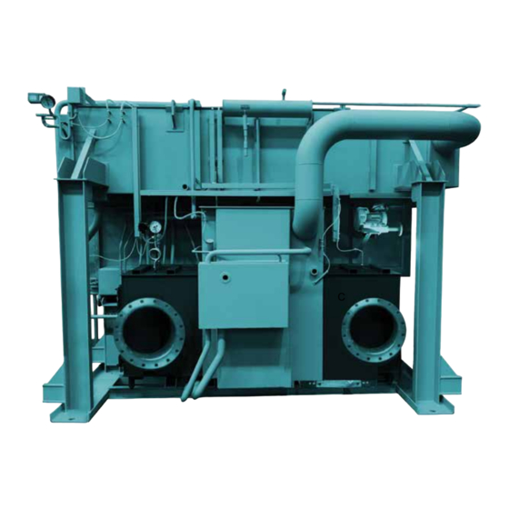
The unit is also equipped with two methods to start and • absorber stop operations: • condenser • touch panel • generators • external signal LABEL CHILLER COMPONENTS Absorber Low Temperature Generator Exhaust Gas Inlet High Temperature Generator Exhaust Gas Outlet LDxxxxx LD22974 FIGURE 1 - YHAU-CE COMPONENTS JOHNSON CONTROLS... -
Page 16: How It Works (Exhaust Gas Units)
FORM 155.35-ICOM2.EN.CE/GB (1018) SECTION 2 – PRODUCT DESCRIPTION DATE: 10/30/2018 The vapor pressure of the lithium bromide solution is HOW IT WORKS (EXHAUST GAS UNITS) lower than the vapor pressure of the refrigerant. The The double effect exhaust gas absorption chiller-heat- vapor pressure of the LiBr solution is directly related er uses deionized water as the refrigerant and lithium to the amount of refrigerant (water) present in the solu-... -
Page 17: Evaporator
FORM 155.35-ICOM2.EN.CE/GB (1018) SECTION 2 – PRODUCT DESCRIPTION DATE: 10/30/2018 EVAPORATOR ABSORBER Liquid refrigerant enters the evaporator where it is dis- The concentrated LiBr solution enters the absorber sec- tributed over the top of the tube bundle. The tubes used tion of the chiller-heater. -
Page 18: Two-Step Evaporator - Absorber
FORM 155.35-ICOM2.EN.CE/GB (1018) SECTION 2 – PRODUCT DESCRIPTION DATE: 10/30/2018 TWO-STEP EVAPORATOR – ABSORBER Concentrated LiBr The evaporator, as well as the absorber, is split into Refrigerant two sections. This design allows for lower LiBr solu- tion concentrations. The lower concentration reduces Chilled pressure, the potential for corrosion, and the risk of Water... -
Page 19: Parallel Flow
FORM 155.35-ICOM2.EN.CE/GB (1018) SECTION 2 – PRODUCT DESCRIPTION DATE: 10/30/2018 PARALLEL FLOW HIGH TEMPERATURE GENERATOR (HTG) The lithium bromide solution flow type is a parallel The high temperature generator section is a flooded, flow cycle. The flow of weak solution pumped from smoke tube design. -
Page 20: Low Temperature Generator
FORM 155.35-ICOM2.EN.CE/GB (1018) SECTION 2 – PRODUCT DESCRIPTION DATE: 10/30/2018 LOW TEMPERATURE GENERATOR CONDENSER The low temperature generator is a falling liquid film The refrigerant vapor from the low temperature gener- type where the hot refrigerant from the high tempera- ator as well as the condensed refrigerant from the high ture generator heats the dilute solution. -
Page 21: Crystallization
FORM 155.35-ICOM2.EN.CE/GB (1018) SECTION 2 – PRODUCT DESCRIPTION DATE: 10/30/2018 CRYSTALLIZATION All units employ some sort of dilution cycle, which ful- All absorption chillers that use lithium bromide and fills this requirement. As long as the unit is allowed to water as the solution and refrigerant pair are subject to dilute itself during an orderly shutdown sequence, the crystallization. - Page 22 FORM 155.35-ICOM2.EN.CE/GB (1018) SECTION 2 – PRODUCT DESCRIPTION DATE: 10/30/2018 THIS PAGE INTENTIONALLY LEFT BLANK. JOHNSON CONTROLS...
-
Page 23: Section 3 - Handling, Storage, Installation And Reassembly
FORM 155.35-ICOM2.EN.CE/GB (1018) DATE: 10/30/2018 SECTION 3 – HANDLING, STORAGE, INSTALLATION AND REASSEMBLY LD18119 This chiller-heater is for air conditioning or cooling a Rigging and lifting should only be done manufacturing process. Transport, store, and use this by a professional rigger in accordance chiller-heater under the following conditions: with a written plan. -
Page 24: Inspection
FORM 155.35-ICOM2.EN.CE/GB (1018) SECTION 3 – HANDLING, STORAGE, INSTALLATION AND REASSEMBLY DATE: 10/30/2018 Each chiller-heater MUST have its own INSPECTION chimney or exhaust gas duct. If two or The unit must be inspected prior to customer use by a more chiller-heaters share a chimney, Johnson Controls Service representative. -
Page 25: Hoisting The Machine
FORM 155.35-ICOM2.EN.CE/GB (1018) SECTION 3 – HANDLING, STORAGE, INSTALLATION AND REASSEMBLY DATE: 10/30/2018 3. Periodic Inspection and Maintenance HOISTING THE MACHINE a. Inspect the machine weekly for damage. Rigging and lifting should only be done by a profes- sional rigger in accordance with a written rigging and b. -
Page 26: Moving The Machine On Rollers
FORM 155.35-ICOM2.EN.CE/GB (1018) SECTION 3 – HANDLING, STORAGE, INSTALLATION AND REASSEMBLY DATE: 10/30/2018 MOVING THE MACHINE ON ROLLERS Use care not to apply shock to the machine. The ma- chine is a high-vacuum vessel containing a corrosive Plan the entrance for the machine by placing the ma- solution. -
Page 27: Figure 5 - Moving The Machine On Tir-Rollers
FORM 155.35-ICOM2.EN.CE/GB (1018) SECTION 3 – HANDLING, STORAGE, INSTALLATION AND REASSEMBLY DATE: 10/30/2018 If using a tri-roller, fit the tri-roller set to each of the four holes shown in the figure below. Machine Leg Hole ( 22) for fitting Tir-roller set Anchor bolt hole Tir-roller set Center hole diameter of Tir-roller... -
Page 28: Figure 6 - Jack-Up Procedure
FORM 155.35-ICOM2.EN.CE/GB (1018) SECTION 3 – HANDLING, STORAGE, INSTALLATION AND REASSEMBLY DATE: 10/30/2018 When jacking up the machine, be sure to fit a jack in Operate the front and rear jacks alternately. each of the jack-up supports as shown in Figure 7 below. Do not jack up the machine more than about 20 mm at a time. -
Page 29: Structural Support And Installation
FORM 155.35-ICOM2.EN.CE/GB (1018) SECTION 3 – HANDLING, STORAGE, INSTALLATION AND REASSEMBLY DATE: 10/30/2018 STRUCTURAL SUPPORT AND When installing the unit indoors, have a specialized company provide a suitable flue or smokestack, as well INSTALLATION as air supply and exhaust equipment. Insufficient air Structural support of the unit must be provided for supply or improper exhaust can cause oxygen starva- maximum efficiency. -
Page 30: Leak Testing
FORM 155.35-ICOM2.EN.CE/GB (1018) SECTION 3 – HANDLING, STORAGE, INSTALLATION AND REASSEMBLY DATE: 10/30/2018 Do not allow negative pressure or any devices that cre- Every week inspect the strainer for the air purge blow- ate negative pressure to operate in the area around the er to prevent clogs and an incomplete air purge. -
Page 31: Use Of Gas
FORM 155.35-ICOM2.EN.CE/GB (1018) SECTION 3 – HANDLING, STORAGE, INSTALLATION AND REASSEMBLY DATE: 10/30/2018 Do not splash water over the machine and its control EXHAUST GAS DAMPER panel. Severe electric shock may result. Exhaust gas dampers are not installed before ship- A warning label for electric shock is pasted at the con- ment. -
Page 32: Vibration And Isolation Details
FORM 155.35-ICOM2.EN.CE/GB (1018) SECTION 3 – HANDLING, STORAGE, INSTALLATION AND REASSEMBLY DATE: 10/30/2018 Do not leave any flammable substance VIBRATION AND ISOLATION DETAILS or easily combustible object near the ma- Before installing the unit, fit rubber vibration isolators chine, flue, smokestack or oil tank. to the unit base as shown in Figure 7 on page 32be- low. -
Page 33: Figure 8 - Nozzle Locations (Example - One Exhaust Gas Outlet Flange)
FORM 155.35-ICOM2.EN.CE/GB (1018) SECTION 3 – HANDLING, STORAGE, INSTALLATION AND REASSEMBLY DATE: 10/30/2018 LD22965 ITEM DESCRIPTION Chilled / Hot Water Inlet Chilled / Hot Water Outlet Cooling Water Inlet Cooling Water Outlet Waste Exhaust Gas Inlet Waste Exhaust Gas Outlet The chiller will be designed according to the different temperature and flow of exhaust gas. -
Page 34: Figure 9 - Nozzle Locations (Example - Two Exhaust Gas Outlet Flanges)
FORM 155.35-ICOM2.EN.CE/GB (1018) SECTION 3 – HANDLING, STORAGE, INSTALLATION AND REASSEMBLY DATE: 10/30/2018 LD22966 The chiller will be designed according ITEM DESCRIPTION to the different temperature and flow of Chilled / Hot Water Inlet exhaust gas. Chilled / Hot Water Outlet The nozzle arrangement will be manu- Cooling Water Inlet factured to the actual chiller design. -
Page 35: Hot Insulation And Cold Insulation Procedure
FORM 155.35-ICOM2.EN.CE/GB (1018) SECTION 3 – HANDLING, STORAGE, INSTALLATION AND REASSEMBLY DATE: 10/30/2018 HOT INSULATION AND COLD INSULATION PROCEDURE 5. Make sure that the outer covering, flanged parts, The installation of insulation is out of and evaporator water chamber casing can be eas- scope. -
Page 36: Figure 10 - Hot And Cold Insulation (Example - One Exhaust Gas Outlet Flange)
FORM 155.35-ICOM2.EN.CE/GB (1018) SECTION 3 – HANDLING, STORAGE, INSTALLATION AND REASSEMBLY DATE: 10/30/2018 Cold Insulation Hot Insulation Exhaust Gas Insulation LD22967 FIGURE 10 - HOT AND COLD INSULATION (EXAMPLE - ONE EXHAUST GAS OUTLET FLANGE) JOHNSON CONTROLS... -
Page 37: Figure 11 - Hot And Cold Insulation (Example -Two Exhaust Gas Outlet Flange)
FORM 155.35-ICOM2.EN.CE/GB (1018) SECTION 3 – HANDLING, STORAGE, INSTALLATION AND REASSEMBLY DATE: 10/30/2018 Cold Insulation Hot Insulation Exhaust Gas Insulation LD22968 FIGURE 11 - HOT AND COLD INSULATION (EXAMPLE -TWO EXHAUST GAS OUTLET FLANGE) JOHNSON CONTROLS... -
Page 38: Figure 12 - Exterior Of Control Panel
FORM 155.35-ICOM2.EN.CE/GB (1018) SECTION 3 – HANDLING, STORAGE, INSTALLATION AND REASSEMBLY DATE: 10/30/2018 FIGURE 12 - EXTERIOR OF CONTROL PANEL JOHNSON CONTROLS... -
Page 39: Section 4 - Technical Data
FORM 155.35-ICOM2.EN.CE/GB (1018) DATE: 10/30/2018 SECTION 4 - TECHNICAL DATA This section includes technical information about the unit, such as weight, dimensions, electrical data, wiring, and sound data. TABLE 3 - TYPICAL OPERATIONAL RANGE PARAMETER ALLOWABLE RANGES Chilled Water In 7 - 25°C Chilled Water Out 4 - 16°C... -
Page 40: Weights And Dimensions
FORM 155.35-ICOM2.EN.CE/GB (1018) SECTION 4 - TECHNICAL DATA DATE: 10/30/2018 Weights and Dimensions The chiller-heater will be designed according to the different temperature and flow of exhaust gas. The weight and dimensions of maximum shipping, operation and emergency will be documented according to the actual chiller- heater results. - Page 41 FORM 155.35-ICOM2.EN.CE/GB (1018) SECTION 4 - TECHNICAL DATA DATE: 10/30/2018 Physical Data The chiller-heater will be designed according to the different temperature and flow of exhaust gas. The physical data will be documented according to the actual chiller-heater results. JOHNSON CONTROLS...
- Page 42 FORM 155.35-ICOM2.EN.CE/GB (1018) SECTION 4 - TECHNICAL DATA DATE: 10/30/2018 Electrical Data The chiller-heater will be designed according to the different temperature and flow of exhaust gas. The electrical data will be documented according to the actual chiller-heater results. JOHNSON CONTROLS...
-
Page 43: Figure 13 - External Connection Terminal Details For Ce
FORM 155.35-ICOM2.EN.CE/GB (1018) SECTION 4 - TECHNICAL DATA DATE: 10/30/2018 LD22918 FIGURE 13 - EXTERNAL CONNECTION TERMINAL DETAILS FOR CE JOHNSON CONTROLS... -
Page 44: Figure 14 - External Connection Details For Gb
FORM 155.35-ICOM2.EN.CE/GB (1018) SECTION 4 - TECHNICAL DATA DATE: 10/30/2018 LD26812 FIGURE 14 - EXTERNAL CONNECTION DETAILS FOR GB JOHNSON CONTROLS... -
Page 45: Table 4 - Contact Specifications
FORM 155.35-ICOM2.EN.CE/GB (1018) SECTION 4 - TECHNICAL DATA DATE: 10/30/2018 TABLE 4 - CONTACT SPECIFICATIONS CONTACT SPECIFICATION ABSORPTION CHILLER-HEATER CONTROL PANEL -> RESISTANCE LOAD EXTERNAL INPUT TERMINAL MAX: AC 240 V 2 A MIN: DC 5 V 1 mA EXTERNAL OUTPUT TERMINAL -> ABSORPTION CHILLER- DC 24 V 6.7 mA HEATER CONTROL PANEL NOTES... -
Page 46: Upper Communication Specification
FORM 155.35-ICOM2.EN.CE/GB (1018) SECTION 4 - TECHNICAL DATA DATE: 10/30/2018 Upper Communication System Configuration UPPER COMMUNICATION SPECIFICATION The configuration of the upper communication system The information in this section applies to the YHAU- is shown in the figure below. CE Series of Exhaust Gas Absorption Chiller-heaters. LD20594f FIGURE 15 - UPPER COMMUNICATION SYSTEM CONFIGURATION FOR CE JOHNSON CONTROLS... -
Page 47: Scope Of Delivery
FORM 155.35-ICOM2.EN.CE/GB (1018) SECTION 4 - TECHNICAL DATA DATE: 10/30/2018 Scope of Delivery Johnson Controls scope of delivery for the upper com- munication system covers the control panels for the upper communication function. The customer must de- liver all other related equipment: concentrator (HUB), installation, wiring, communication program for the central monitoring unit, and so on. -
Page 48: Communication Data
FORM 155.35-ICOM2.EN.CE/GB (1018) SECTION 4 - TECHNICAL DATA DATE: 10/30/2018 Communication Data TABLE 8 - READ COMMAND ITEM DISPLAY UNIT ADDRESS CONTENT Set Point (Chilled / Hot water outlet °C 00001 0050~1000 unit, 1 unit=0.1 °C temp.) Automatic stop temp. at cooling °C 00003 0040~1000 unit, 1 unit=0.1 °C... -
Page 49: User-Created
FORM 155.35-ICOM2.EN.CE/GB (1018) SECTION 4 - TECHNICAL DATA DATE: 10/30/2018 TABLE 9 - WRITE COMMAND ITEM ADDRESS CONTENT Chiller-heater operation signal 02001 ON at Chiller-heater OPERATION, PULSE SIGNAL Chiller-heater stop signal 02002 ON at Chiller-heater STOP, PULSE SIGNAL Set point 00203 0050~1000 unit, 1 unit=0.1°C User-Created... -
Page 50: 2-Wire Cable Diagrams Without Adaptor
FORM 155.35-ICOM2.EN.CE/GB (1018) SECTION 4 - TECHNICAL DATA DATE: 10/30/2018 TABLE 11 - CABLE DIAGRAM (RS-422 OR RS485) PIN CONNECTION PIN. RS-422 OR RS-485 SIGNAL NAME DIRECTION MEANING Input Receive Data A (+) Input Receive Data B (-) Output Send Data A (+) Output Data Terminal Ready A (+) Signal Ground... -
Page 51: Wire Type Cable Diagrams Without Adaptor
FORM 155.35-ICOM2.EN.CE/GB (1018) SECTION 4 - TECHNICAL DATA DATE: 10/30/2018 LD21547 FIGURE 17 - 2-WIRE N:1 CONNECTION WITH USER-CREATED CABLE 4 Wire Type Cable Diagrams Without Adaptor The following are sample cable diagrams for 4-wire type connections. LD21548 FIGURE 18 - 4-WIRE 1:1 CONNECTION WITH USER-CREATED CABLE JOHNSON CONTROLS... -
Page 52: Figure 19 - 4-Wire N:1 Connection With User Created Cable
FORM 155.35-ICOM2.EN.CE/GB (1018) SECTION 4 - TECHNICAL DATA DATE: 10/30/2018 LD21549 FIGURE 19 - 4-WIRE N:1 CONNECTION WITH USER CREATED CABLE. The next table contains information about the commu- nication specifications needed for the Modbus RTU. See Table 8 on page 48 for information about the Read Command or Table 9 on page 49 for informa- tion about the Write Command. -
Page 53: Figure 20 - Sample Sound Testing
FORM 155.35-ICOM2.EN.CE/GB (1018) SECTION 4 - TECHNICAL DATA DATE: 10/30/2018 Evaporator side B side A side Background Noise Generator side LD22970 FIGURE 20 - SAMPLE SOUND TESTING TABLE 13 - SOUND DATA OCTAVE BAND LOCATION* OVERALL 31.5 Hz 63 Hz 125 Hz 250 Hz 500 Hz... - Page 54 FORM 155.35-ICOM2.EN.CE/GB (1018) SECTION 4 - TECHNICAL DATA DATE: 10/30/2018 THIS PAGE INTENTIONALLY LEFT BLANK. JOHNSON CONTROLS...
-
Page 55: Section 5 - Commissioning
5. Operate the pump and open the valve. lation and start-up of the unit. The steps and procedures MUST be performed by a YORK/Johnson Controls 6. Read and record the delivery pressure of the solu- Service person prior to customer use. -
Page 56: Precautions For The Use Of Water
FORM 155.35-ICOM2.EN.CE/GB (1018) SECTION 5 - COMMISSIONING DATE: 10/30/2018 When the flow rate change of the chilled / hot water PRECAUTIONS FOR THE USE OF WATER is controlled (if the flow rate change function is in- Staining and corrosion of the tubes in the evaporator, stalled), the load change speed is limited. -
Page 57: Start The Chiller-Heater
FORM 155.35-ICOM2.EN.CE/GB (1018) SECTION 5 - COMMISSIONING DATE: 10/30/2018 STOP THE CHILLER-HEATER START THE CHILLER-HEATER 1. To stop the chiller-heater, press the STOP but- Before starting the chiller-heater, review the following: ton on the Control Panel Main screen. To stop the •... -
Page 58: Figure 21 - Cooling Start Diagram
FORM 155.35-ICOM2.EN.CE/GB (1018) SECTION 5 - COMMISSIONING DATE: 10/30/2018 Turn ON power source Cooling Water pump Chiller-Heater stops interlock ON? within 3 min. with failure alarm Initialize Self-Check Mechanism Remote Remote / Local Mode selection Local Exhaust gas forced bypass switch OFF? Local operation ON Remote Operation ON Chiller-Heater stops... -
Page 59: Figure 22 - Cooling Start Diagram
FORM 155.35-ICOM2.EN.CE/GB (1018) SECTION 5 - COMMISSIONING DATE: 10/30/2018 Dilution status XG input preparation Dilution complete? starts. Solution pumps and Refrigerant pump stop Temperature control with XG bypass damper starts. Cooling water pump stop XG outlet temp ≤ low XG outlet temp. -
Page 60: Figure 23 - Cooling Stop Diagram
FORM 155.35-ICOM2.EN.CE/GB (1018) SECTION 5 - COMMISSIONING DATE: 10/30/2018 Chiller heater operating Remote Remote / Local Mode selection Failure alarm? Local Remote stop Local stop command ON command ON Failure without dilution? The chiller stops without dilution due to the following alarm. Solution circulation Pump Abnormal Solution spray Pump Abnormal Refrigerant Pump Abnormal... -
Page 61: Figure 24 - Sequential Operation Flowchart
FORM 155.35-ICOM2.EN.CE/GB (1018) SECTION 5 - COMMISSIONING DATE: 10/30/2018 Sequential Operation Sequential Operation Chilled / Hot Water Air Conditioner Pump Interlock Cooling Water Pump Sequential Operation Interlock Sequential Operation Cooling Tower Interlock (Answerback) Gas Engine Other interlock device and equipment (Earthquake sensor, gas leak detector, ventilation fan, and other relevant interlock equipment. Other Sequential Operation device and equipment (example: ventilation fan) NOTES: 1. - Page 62 FORM 155.35-ICOM2.EN.CE/GB (1018) SECTION 4 - TECHNICAL DATA DATE: 10/30/2018 THIS PAGE INTENTIONALLY LEFT BLANK. JOHNSON CONTROLS...
-
Page 63: Section 6 - Operation
FORM 155.35-ICOM2.EN.CE/GB (1018) DATE: 10/30/2018 SECTION 6 – OPERATION YHAU-CE CONTROL CENTER The YHAU-CE Control Center, furnished as standard COMMON ITEMS on each chiller-heater, allows for efficiency, monitor- Buttons are listed in the order they are ing, data recording, chiller-heater protection, and op- seen on the screen: left to right and top erating ease. -
Page 64: Change Numeric Values
FORM 155.35-ICOM2.EN.CE/GB (1018) SECTION 6 – OPERATION DATE: 10/30/2018 CHANGE NUMERIC VALUES Many numeric values, such as the set point and the rang- es on the Trend screen, can be changed. Here’s how: 1. Touch the number to be changed. A numeric key- pad appears. - Page 65 FORM 155.35-ICOM2.EN.CE/GB (1018) SECTION 6 – OPERATION DATE: 10/30/2018 For information on how to use the key- pad, see Change Numeric Values on page LD21987 LD21988 11. Press the Date and Time button in the lower right corner of the screen. LD21987 LD21987 7.
- Page 66 FORM 155.35-ICOM2.EN.CE/GB (1018) SECTION 6 – OPERATION DATE: 10/30/2018 15. Check the date and time in the lower right corner of the screen LD22165 LD22165 20. The Exit screen displays. Press the Yes button. LD22162 LD22162 16. If the changes are correct, press the Save button. LD22166 LD22166 21.
-
Page 67: Operating Status
FORM 155.35-ICOM2.EN.CE/GB (1018) SECTION 6 – OPERATION DATE: 10/30/2018 MAIN SCREEN LD26793a FIGURE 26 - MAIN SCREEN OPERATING STATUS The Main screen is the ONLY screen where you can start or stop the chiller-heater. The two buttons in the lower left corner of the screen are: •... - Page 68 FORM 155.35-ICOM2.EN.CE/GB (1018) SECTION 6 – OPERATION DATE: 10/30/2018 On the Main screen, the lit buttons tell you which sys- The Waste Gas Damper Status section contains the fol- tems are running. lowing sub-sections: On the upper left of the screen below the LOCAL and •...
-
Page 69: Figure 27 - Data Screen
FORM 155.35-ICOM2.EN.CE/GB (1018) SECTION 6 – OPERATION DATE: 10/30/2018 DATA SCREEN LD26795 FIGURE 27 - DATA SCREEN XG Generator Temp.: temperature of the concen- The Data screen Measured Values section shows the trated solution in the high temperature generator following: Chilled / Hot Water Inlet Temp.: temperature of the XG Generator Pressure: pressure in the high tem- chilled / hot water measured as it enters the evaporator... - Page 70 FORM 155.35-ICOM2.EN.CE/GB (1018) SECTION 6 – OPERATION DATE: 10/30/2018 The Operation Hours section shows the following: • Refrige. Pump: total number of times the refrig- erant pump started • Operating: total operating hours of the absorption machine in cooling mode •...
-
Page 71: Figure 28 - Alarm History Screen
FORM 155.35-ICOM2.EN.CE/GB (1018) SECTION 6 – OPERATION DATE: 10/30/2018 ALARM HISTORY SCREEN LD21965 FIGURE 28 - ALARM HISTORY SCREEN The Single Down Arrow button moves you downward The Alarm History Screen shows information for the last alarm or failure and up to twenty previous events. through the list one event at a time. -
Page 72: Figure 29 - Trend Screen
FORM 155.35-ICOM2.EN.CE/GB (1018) SECTION 6 – OPERATION DATE: 10/30/2018 TREND SCREEN LD26796 FIGURE 29 - TREND SCREEN Press the Trend button on the Data screen to access this information. There are two Trend screens. The first screen graphi- cally illustrates the trend of the temperature for the fol- lowing: •... -
Page 73: Figure 30 - Trend Screen - Part 2
FORM 155.35-ICOM2.EN.CE/GB (1018) SECTION 6 – OPERATION DATE: 10/30/2018 TREND SCREEN - PART 2 LD21531 FIGURE 30 - TREND SCREEN - PART 2 Press the Left Arrow button to return to the previous The second Trend screen shows you the trend of the Trend screen. -
Page 74: Failure
FORM 155.35-ICOM2.EN.CE/GB (1018) SECTION 6 – OPERATION DATE: 10/30/2018 FAILURE SCREEN LD26798 FIGURE 31 - FAILURE SCREEN If there is a failure in the unit this screen automatically displays. The red failure light at the top right of the screen lights. At that time, you can see which failure button is lit. -
Page 75: Table 16 - Failure List
FORM 155.35-ICOM2.EN.CE/GB (1018) SECTION 6 – OPERATION DATE: 10/30/2018 The failures addressed in this screen are listed in the following table. TABLE 16 - FAILURE LIST OPERATION BUTTON LABEL AT FAILURE CAUSE COUNTERMEASURES (FAILURE NAME) OCCURRENCE Operation interlock (chilled / hot water pump, or other pumps) signal was Check interlocked equipment for Operation interlock... - Page 76 FORM 155.35-ICOM2.EN.CE/GB (1018) SECTION 6 – OPERATION DATE: 10/30/2018 TABLE 16 - FAILURE LIST OPERATION BUTTON LABEL AT FAILURE CAUSE COUNTERMEASURES (FAILURE NAME) OCCURRENCE The inlet damper open limit switch did Inlet Damper Open not turn ON within 180 seconds after it Failure received the open signal.
- Page 77 FORM 155.35-ICOM2.EN.CE/GB (1018) SECTION 6 – OPERATION DATE: 10/30/2018 TABLE 16 - FAILURE LIST OPERATION BUTTON LABEL AT FAILURE CAUSE COUNTERMEASURES (FAILURE NAME) OCCURRENCE The air damper motor current exceeded Air Damper Contact your local Johnson Controls the rated value and the thermal relay Overcurrent Service Center.
- Page 78 FORM 155.35-ICOM2.EN.CE/GB (1018) SECTION 6 – OPERATION DATE: 10/30/2018 TABLE 16 - FAILURE LIST OPERATION BUTTON LABEL AT FAILURE CAUSE COUNTERMEASURES (FAILURE NAME) OCCURRENCE Solution circulation pump motor current Solution Circulation exceeded the rated value and activated P Abnormal (Solution the thermal relay.
-
Page 79: Alarm
FORM 155.35-ICOM2.EN.CE/GB (1018) SECTION 6 – OPERATION DATE: 10/30/2018 ALARM SCREEN LD21535 FIGURE 32 - ALARM SCREEN If an alarm occurs, the orange Alarm light at the top Press the lit alarm button to access an on-screen han- of any screen lights. Press the ALARM button to see dling guide for each item. -
Page 80: Table 17 - Alarm List
FORM 155.35-ICOM2.EN.CE/GB (1018) SECTION 6 – OPERATION DATE: 10/30/2018 The alarms are listed in the following table. TABLE 17 - ALARM LIST BUTTON LABEL (ALARM CAUSE OF ALARM AND COUNTERMEASURES NAME) CONDITION TO RESET • The air purge blower motor current exceeded the rated value. - Page 81 FORM 155.35-ICOM2.EN.CE/GB (1018) SECTION 6 – OPERATION DATE: 10/30/2018 BUTTON LABEL (ALARM CAUSE OF ALARM AND COUNTERMEASURES NAME) CONDITION TO RESET • The cooling water inlet temperature rose enough to High Cooling Water Inlet trigger the load limit operation • Check the cooling water inlet temperature control system.
-
Page 82: Control Parameter
FORM 155.35-ICOM2.EN.CE/GB (1018) SECTION 6 – OPERATION DATE: 10/30/2018 SETTING SCREEN LD26800 FIGURE 33 - SETTING SCREEN CONTROL PARAMETER The Control Parameter section of the Setting screen is • Automatic Restart Differential: the temperature used to enter parameters for the cooling and heating op- difference between the temperature at which the eration, such as target temperature, automatic stop tem- chiller-heater will automatically stop and the tem-... -
Page 83: Operation Switch
FORM 155.35-ICOM2.EN.CE/GB (1018) SECTION 6 – OPERATION DATE: 10/30/2018 OPERATION SWITCH • Purge Mode: the Auto and Manual buttons con- trol how the purge operation is managed. The Operation Switch section contains a group of but- tons that you can use to control the unit. •... - Page 84 FORM 155.35-ICOM2.EN.CE/GB (1018) DATE: 10/30/2018 THIS PAGE INTENTIONALLY LEFT BLANK JOHNSON CONTROLS...
-
Page 85: Section 7 - Maintenance
FORM 155.35-ICOM2.EN.CE/GB (1018) DATE: 10/30/2018 SECTION 7 – MAINTENANCE When inspecting and maintaining the absorption chill- Contact your local Johnson Controls er-heater, note the following: Service Office for inspection and main- tenance of the machine. Improper in- • Never splash water over the electrical parts in- spection and maintenance can cause a stalled in the control panel and absorption chiller- machine problem or injure workers. -
Page 86: Purge Valves
FORM 155.35-ICOM2.EN.CE/GB (1018) SECTION 7 – MAINTENANCE DATE: 10/30/2018 PURGE VALVES The vacuum level should be less than -0.1 MPaG. The chiller-heater is equipped with the purge valves shown in Figure 34 on page 88. For operation of the valves, see the Performance Check Method of Vacuum Pump on page 87. -
Page 87: Performance Check Method Of Vacuum Pump
FORM 155.35-ICOM2.EN.CE/GB (1018) SECTION 7 – MAINTENANCE DATE: 10/30/2018 PERFORMANCE CHECK METHOD OF VACUUM PUMP When the purge unit starts, check the performance of 4. Set the valves according to pattern A shown in Ta- the vacuum pump first according to the following pro- ble 19 on page 90. -
Page 88: Figure 34 - Location Of Manual Valve In Purging System (Example)
FORM 155.35-ICOM2.EN.CE/GB (1018) SECTION 7 – MAINTENANCE DATE: 10/30/2018 LD22001 Purge solenoid valve (SV2) Purge solenoid valve (SV1) Purge solenoid valve (SV2) Purge main valve (V20) Purge solenoid valve (SV1) Purge valve for purge tank line (V19) Purge main valve (V20) Purge valve for purge tank line (V18) Purge valve for purge tank line (V19) Purge valve for absorber line (V17) -
Page 89: Purge Procedure
FORM 155.35-ICOM2.EN.CE/GB (1018) SECTION 7 – MAINTENANCE DATE: 10/30/2018 PURGE PROCEDURE 7. If no problems are found, open valve V17. Make sure the valve is completely open. Non-condensable gas must be purged from the chiller- heater to maintain its performance and prevent dete- rioration of its internal parts. -
Page 90: Automatic Method To Purge Non-Condensable Gas From Purging Tank
FORM 155.35-ICOM2.EN.CE/GB (1018) SECTION 7 – MAINTENANCE DATE: 10/30/2018 Automatic Method to Purge Non-condensable During the automatic purge operation, the vacuum Gas from Purging Tank pump starts when the purging tank pressure increases to 7 kPa abs and stops when it decreases to 3 kPa abs. This chiller-heater has an automatic purge system. -
Page 91: Figure 35 - Purge System
FORM 155.35-ICOM2.EN.CE/GB (1018) SECTION 7 – MAINTENANCE DATE: 10/30/2018 FIGURE 35 - PURGE SYSTEM JOHNSON CONTROLS... -
Page 92: Figure 36 - Process And Instrumentation Diagram - Cooling Only
FORM 155.35-ICOM2.EN.CE/GB (1018) SECTION 7 – MAINTENANCE DATE: 10/30/2018 LD26801 FIGURE 36 - PROCESS AND INSTRUMENTATION DIAGRAM - COOLING ONLY JOHNSON CONTROLS... -
Page 93: Refrigerant Refining Method
FORM 155.35-ICOM2.EN.CE/GB (1018) SECTION 7 – MAINTENANCE DATE: 10/30/2018 REFRIGERANT REFINING METHOD MANUAL REFRIGERANT BLOWDOWN AND DILUTION METHOD With an increase in the operation time of the chiller- When the chiller-heater stops suddenly due to a power heater, some of the solution can mix in with the refrig- erant. -
Page 94: Decrystallization Method
FORM 155.35-ICOM2.EN.CE/GB (1018) SECTION 7 – MAINTENANCE DATE: 10/30/2018 DECRYSTALLIZATION METHOD 6. Turn the spindle in the valve to the left with the 8 mm hexagon wrench. Even if the solution in the absorption chiller-heater is The refrigerant in the refrigerant tank crystallized during operation, it can be melted if the diverts into the absorber. -
Page 95: Precautions For Decrystallization
FORM 155.35-ICOM2.EN.CE/GB (1018) SECTION 7 – MAINTENANCE DATE: 10/30/2018 25. Set the temperature controllers to automatic mode • When you start the chiller-heater after decrys- for the waste exhaust gas. tallization, discharge the chilled / hot water and the cooling water first. The basin material of the 26. - Page 96 FORM 155.35-ICOM2.EN.CE/GB (1018) SECTION 7 – MAINTENANCE DATE: 10/30/2018 TABLE 20 - MAINTENANCE AND INSPECTION TASK CONTENTS FREQUENCY SCOPE Measure the insulation resistance of the main circuit and motors (solution pump, refrigerant pump) mainly to check Measurement of insulation for lowering of insulation. When measuring the insulation resistance of electric resistance, be sure to disconnect the wires of the devices...
- Page 97 FORM 155.35-ICOM2.EN.CE/GB (1018) SECTION 7 – MAINTENANCE DATE: 10/30/2018 TABLE 20 - MAINTENANCE AND INSPECTION TASK CONTENTS FREQUENCY SCOPE Repair paint (epoxy paint) Chilled / hot water: of inside wall of chilled / Every 2 years Repair the paint of the inside wall as needed. hot water and cooling Cooling water: Yearly waterboxes...
-
Page 98: Refrigerant Pump Manual Stop
FORM 155.35-ICOM2.EN.CE/GB (1018) SECTION 7 – MAINTENANCE DATE: 10/30/2018 Refrigerant Pump Manual Stop The purge solenoid valves open. The purge operation begins. The refrigerant pump can be stopped manually for maintenance purposes. It can be stopped even while 4. Press the Manual Purge OFF button when the the chiller-heater is operating. -
Page 99: Blower Fan Manual Stop
FORM 155.35-ICOM2.EN.CE/GB (1018) SECTION 7 – MAINTENANCE DATE: 10/30/2018 After maintenance of the air purge blower fan is com- Blower Fan Manual Stop plete, be sure to press the Blower Fan Auto button. If 1. Navigate to the Control Panel Setting screen. the chiller-heater continues to operate with the blower 2. -
Page 100: Lifespan Of Common Parts
FORM 155.35-ICOM2.EN.CE/GB (1018) SECTION 7 – MAINTENANCE DATE: 10/30/2018 LIFESPAN OF COMMON PARTS The replacement periods for some parts are shown below. The following periods are shown for reference only. The replacement period may be changed ac- cording to the actual environment, frequency of use, and other contributing factors. -
Page 101: Figure 37 - Chilled / Hot Water, Cooling Water And Waste Exhaust Gas System (Example Of One Exhaust Gas Outlet Flange)
FORM 155.35-ICOM2.EN.CE/GB (1018) SECTION 7 – MAINTENANCE DATE: 10/30/2018 LIFESPAN AND REPLACEMENT PART NAME REMARKS INTERVAL Solution or refrigerant pump shut Every 48,000 hours off valve Temperature controller (TIC) Every 30,000 hours Sequencer unit Relay Timer Every 30,000 hours Fuse DC power unit Magnetic contactor, thermal relay Battery for sequencer unit... -
Page 102: Water Quality Control
FORM 155.35-ICOM2.EN.CE/GB (1018) SECTION 7 – MAINTENANCE DATE: 10/30/2018 Exhaust Gas Chimney Temperature gauge (or sensor) By-pass Damper Pressure gauge Expansion joint Exhaust Gas Outlet Damper 1 Gas Engine Exhaust Gas Exhaust Gas Inlet Damper Outlet Damper 2 Radiation Heat Exchanger (out of scope) Cooling Purge Blower... -
Page 103: Chemical Water Treatment
FORM 155.35-ICOM2.EN.CE/GB (1018) SECTION 7 – MAINTENANCE DATE: 10/30/2018 CHEMICAL WATER TREATMENT CHEMICAL TREATMENT Since the mineral content of the water circulated Corrosion inhibitors are attracted chemically to metal through the evaporator, condenser, absorber and the surfaces when they are corroded. They may also form water used may corrode the tubes or deposit heat resis- inert protective compounds over the metal surfaces. -
Page 104: Table 23 - Tendency Of Generation Of Scales And Corrosion By Quality Of Cooling Water
FORM 155.35-ICOM2.EN.CE/GB (1018) SECTION 7 – MAINTENANCE DATE: 10/30/2018 TABLE 23 - TENDENCY OF GENERATION OF SCALES AND CORROSION BY QUALITY OF COOLING WATER GENERAL TENDENCY QUALITY OF COOLING WATER SCALE AND ITS COLOR CORROSION AND ITS COLOR Dark brown Hard scales are generated Corrosion of iron and ~ Pale... -
Page 105: Table 24 - Chilled / Hot And Cooling Water Quality Control (Maximum Concentrations)
FORM 155.35-ICOM2.EN.CE/GB (1018) SECTION 7 – MAINTENANCE DATE: 10/30/2018 TABLE 24 - CHILLED / HOT AND COOLING WATER QUALITY CONTROL (MAXIMUM CONCENTRATIONS) COOLING WATER SYSTEM CHILLED / HOT WATER NON- TENDENCY CIRCULATING SYSTEM CIRCULATING TYPE WATER ELEMENT (1) (6) CIRCULATING CIRCULATING REPLENISH PASSING... -
Page 106: Storage Method Of The Chiller-Heater
FORM 155.35-ICOM2.EN.CE/GB (1018) SECTION 7 – MAINTENANCE DATE: 10/30/2018 STORAGE METHOD OF CHILLER-HEATER Wet Storage Method The wet storage method may be used when there is no If the chiller-heater needs to be stored long-term, the concern about chilled / hot water and cooling water storage method varies. -
Page 107: Dry Storage Method
FORM 155.35-ICOM2.EN.CE/GB (1018) SECTION 7 – MAINTENANCE DATE: 10/30/2018 Dry Storage Method 4. Circulate the clear water through the water pump for one hour to clean debris from the water pump. The dry storage method should be used if the chilled / hot water system and/or the cooling water system may 5. -
Page 108: Storage Method Of The Cooling Water During Heating Operation Period
FORM 155.35-ICOM2.EN.CE/GB (1018) SECTION 7 – MAINTENANCE DATE: 10/30/2018 TABLE 26 - DRY STORAGE METHOD PART STORAGE METHOD Chilled / hot water system Dried and pressurized with Nitrogen Storage Period; less than 6 months (0.01~0.02 MPaG) Cooling water system Inside of shells Vacuum Chilled / hot water system Dried and pressurized with Nitrogen... -
Page 109: Work Procedure
FORM 155.35-ICOM2.EN.CE/GB (1018) SECTION 7 – MAINTENANCE DATE: 10/30/2018 Work Procedure 5. Drain all of the cooling water from the absorber 1. If the quality of the remaining cooling water has and condenser. deteriorated, drain all the cooling water from the absorber and the condenser. -
Page 110: Dry Storage
FORM 155.35-ICOM2.EN.CE/GB (1018) SECTION 7 – MAINTENANCE DATE: 10/30/2018 Dry Storage Work Procedure Dry storage involves draining the water from the tubes. 1. Drain all of the cooling water from the absorber It most often used when the unit is installed in an out- and the condenser. -
Page 111: Figure 41 - Duhring Diagram Ptx Chart (°F)
FORM 155.35-ICOM2.EN.CE/GB (1018) SECTION 7 – MAINTENANCE DATE: 10/30/2018 DUHRING DIAGRAM PTX CHART (F°) LD14221f FIGURE 41 - JOHNSON CONTROLS... -
Page 112: Figure 42 - Duhring Diagram Ptx Chart (°C)
FORM 155.35-ICOM2.EN.CE/GB (1018) SECTION 6 – OPERATION DATE: 10/30/2018 FIGURE 42 - DUHRING DIAGRAM PTX CHART (°C) JOHNSON CONTROLS... -
Page 113: Figure 43 - Specific Gravity - Concentration (°F)
FORM 155.35-ICOM2.EN.CE/GB (1018) SECTION 6 – OPERATION DATE: 10/30/2018 SPECIFIC GRAVITY - CONCENTRATION TABLES AQUEOUS LiBr SOLUTIONS Refrigerant Table (%LiBr by Weight) Temperature F S.G. 1.00 –– –– –– –– –– –– 0.08 0.18 0.28 0.37 0.47 0.57 0.67 1.01 0.98 1.08 1.17... -
Page 114: Figure 44 - Specific Gravity - Concentration (°C)
FORM 155.35-ICOM2.EN.CE/GB (1018) SECTION 6 – OPERATION DATE: 10/30/2018 SPECIFIC GRAVITY – CONCENTRATION TABLES AQUEOUS LiBr SOLUTIONS Refrigerant Table (%LiBr by Weight) Temperature °C S.G. 10.0 12.8 15.6 18.3 21.1 23.9 26.7 29.4 32.2 35.0 37.8 1.00 0.08 0.18 0.28 0.37 0.47 0.57... -
Page 115: Section 8 - Troubleshooting
FORM 155.35-ICOM2.EN.CE/GB (1018) DATE: 10/30/2018 SECTION 8 – TROUBLESHOOTING If the chiller-heater malfunctions while it is operating, • Check the valves and pumps of the cooling water it is imperative to find and correct the problem. If the system and confirm that the specified flow rate is cause is not clear, and performing a countermeasure secured. -
Page 116: Table 28 - Refrigerant Overcooled
FORM 155.35-ICOM2.EN.CE/GB (1018) SECTION 8 – TROUBLESHOOTING DATE: 10/30/2018 REFRIGERANT OVERCOOLED ITEM CAUSE COUNTERMEASURE Chilled / hot water flow See if the chilled / hot water flow rate changes quickly (particularly in the case rate drops or changes of variable flow rate specification). If the flow rate changes suddenly, apply a suddenly. -
Page 117: Troubleshooting Performance Issues
FORM 155.35-ICOM2.EN.CE/GB (1018) SECTION 8 – TROUBLESHOOTING DATE: 10/30/2018 TROUBLESHOOTING PERFORMANCE ISSUES numbers 1 to 7, it may be one of numbers 8 through If the performance is low while the capacity control 14. In this case, contact your local Johnson Controls valve is fully open or if the capacity control valve does Service Center immediately. -
Page 118: Vacuum Pump
FORM 155.35-ICOM2.EN.CE/GB (1018) SECTION 8 – TROUBLESHOOTING DATE: 10/30/2018 VACUUM PUMP When the Purge Abnormal alarm button lights or ed. See Table 31 on page 118. Or, the vacuum pump the vacuum level of the purging line did not reach the may need to be disassembled for inspection. -
Page 119: Table 34 - Interlock Troubleshooting
FORM 155.35-ICOM2.EN.CE/GB (1018) SECTION 8 – TROUBLESHOOTING DATE: 10/30/2018 TABLE 33 - INTERLOCK TROUBLESHOOTING ITEM CAUSE COUNTERMEASURE There is an interlock error. The error is caused by • Check the interlocked devices. the chilled / hot water pump operation answerback •... -
Page 120: Table 36 - Chilled Water Overcooling Troubleshooting
FORM 155.35-ICOM2.EN.CE/GB (1018) SECTION 8 – TROUBLESHOOTING DATE: 10/30/2018 TABLE 35 - CHILLED WATER OVERCOOLING TROUBLESHOOTING ITEM CAUSE COUNTERMEASURE Chilled water flow rate drops or Using a flow rate meter, check to see if the chilled water flow changes suddenly. rate changes suddenly (particularly in case of variable flow rate specification). -
Page 121: Table 38 - Other Failure Troubleshooting
FORM 155.35-ICOM2.EN.CE/GB (1018) SECTION 8 – TROUBLESHOOTING DATE: 10/30/2018 TABLE 37 - OTHER FAILURE TROUBLESHOOTING ITEM CAUSE COUNTERMEASURE The HG (XG) solution level dropped. The • See Performance Check Method of Vacuum Pump on page solution level of the HG (XG) decreased when the waste exhaust gas was •... -
Page 122: Table 39 - Damper Failure Troubleshooting
FORM 155.35-ICOM2.EN.CE/GB (1018) SECTION 8 – TROUBLESHOOTING DATE: 10/30/2018 TABLE 38 - DAMPER FAILURE TROUBLESHOOTING ITEM CAUSE COUNTERMEASURE There was an air damper open failure. The open limit switch does not turn ON after 180 seconds have elapsed since the air purge damper opening command. There was an air damper close failure. -
Page 123: Figure 45 - Trouble Sequence Flowchart
FORM 155.35-ICOM2.EN.CE/GB (1018) SECTION 8 – TROUBLESHOOTING DATE: 10/30/2018 Chiller-heater operating Failure alarm? Alarm buzzer Failure lamp lit External output signal Press BUZZER STOP failure lamp lights. Button EG input stops Failure without dilution? (see note) Dilution starts Minimum dilution time passed? HEX temp. -
Page 124: Actions To Take Against Power Failure
FORM 155.35-ICOM2.EN.CE/GB (1018) SECTION 8 – TROUBLESHOOTING DATE: 10/30/2018 ACTIONS TO TAKE AGAINST POWER FAILURE Power failure If the main power fails, take the following actions. Chiller-heater stops Power is restored Power failure interval is shorter Continue running machine than the controller back up interval Power failure interval is shorter than 5 minutes Power failure interval is shorter... -
Page 125: Section 9 - Decommissioning, Dismantling, And Disposal
FORM 155.35-ICOM2.EN.CE/GB (1018) DATE: 10/30/2018 SECTION 9 - DECOMMISSIONING, DISMANTLING, AND DISPOSAL Unless otherwise indicated, the operations described 8. If glycol was used in the water system, or chemi- below can be performed by any properly trained main- cal additives are contained, dispose of the solution tenance technician. - Page 126 FORM 155.35-ICOM2.EN.CE/GB (1018) DATE: 10/30/2018 THIS PAGE INTENTIONALLY LEFT BLANK JOHNSON CONTROLS...
- Page 127 A. General ture part of the exhaust gas line ....... 1. All major pieces, boxes, and crates have been received and accounted for by a YORK/Johnson B. Piping Controls Service Representative......1. Piping is installed between the unit and the source 2.
- Page 128 FORM 155.35-ICOM2.EN.CE/GB (1018) SECTION 9 - DECOMMISSIONING, DISMANTLING, AND DISPOSAL DATE: 10/30/2018 FORM 155.31-CL1 ISSUE DATE: 11/20/2017 C. Valve and Sensor Check 6. Clean the mesh strainer on the line ......1. Adjusting valves are set correctly......7. Air vent valves and drain valves are closed on the: a.
- Page 129 FORM 155.35-ICOM2.EN.CE/GB (1018) SECTION 9 - DECOMMISSIONING, DISMANTLING, AND DISPOSAL DATE: 10/30/2018 FORM 155.31-CL1 ISSUE DATE: 11/20/2017 START UP CHECKLIST 4. Navigate to the Setting screen in the Control Panel. 5. Press the Operation Mode Cooling button....A. Operation Check 6.
- Page 130 FORM 155.35-ICOM2.EN.CE/GB (1018) SECTION 9 - DECOMMISSIONING, DISMANTLING, AND DISPOSAL DATE: 10/30/2018 FORM 155.31-CL1 ISSUE DATE: 11/20/2017 19. Check for water leaks around the waste hot water 37. Check that the waste hot water temperature is box cover during operation with waste hot water within the normal range.
- Page 131 FORM 155.35-ICOM2.EN.CE/GB (1018) SECTION 9 - DECOMMISSIONING, DISMANTLING, AND DISPOSAL DATE: 10/30/2018 FORM 155.31-CL1 ISSUE DATE: 11/20/2017 D. Operation instruction Review the operation and maintenance instructions in the manual with the customer........a. Customer Names: NOTE: We recommend you operate the unit with a limited load for the first 50-200 hours.
- Page 132 FORM 155.35-ICOM2.EN.CE/GB (1018) SECTION 9 - DECOMMISSIONING, DISMANTLING, AND DISPOSAL DATE: 10/30/2018 FORM 155.31-CL1 ISSUE DATE: 11/20/2017 EXHAUST GAS ABSORPTION CHILLER-HEATER COMMISSIONING DATA SHEET (1/2) User: Model: YHAU MFG. No.: User's machine code: Insulation Resistance Electric Power Supply Standard: 5 MΩ or more (with 500 V megger) R-Gnd S-Gnd T-Gnd...
- Page 133 FORM 155.35-ICOM2.EN.CE/GB (1018) SECTION 9 - DECOMMISSIONING, DISMANTLING, AND DISPOSAL DATE: 10/30/2018 FORM 155.31-CL1 ISSUE DATE: 11/20/2017 EXHAUST GAS ABSORPTION CHILLER-HEATER COMMISSIONING DATA SHEET (2/2) User: Model: YHAU MFG. No.: User's machine code: Running Data Date: Measured by Specification Standard Inlet damper position Damper indicator Outlet damper position...
- Page 134 FORM 155.35-ICOM2.EN.CE/GB (1018) SECTION 9 - DECOMMISSIONING, DISMANTLING, AND DISPOSAL DATE: 10/30/2018 FORM 155.31-CL1 ISSUE DATE: 11/20/2017 NOTES: Same Operating hours hours Height Number of purge times times Fill out each specification pressure drop according to the factory inspection report (actual value). If differential pressure gauge (DPG) is not available, calculate each pressure drop.
- Page 135 FORM 155.35-ICOM2.EN.CE/GB (1018) SECTION 9 - DECOMMISSIONING, DISMANTLING, AND DISPOSAL DATE: 10/30/2018 FORM 155.31-CL1 ISSUE DATE: 11/20/2017 PURGE AMOUNT DATA SHEET (1/1) User: Model: YHAU MFG. No.: User's machine code: Measured Date: Measured by: Purge Amount from Purge Tank Flame Reaction Test Standard: 4.0 cc per min.
- Page 136 5000 Renaissance Drive, New Freedom, Pennsylvania USA 17349 800-861-1001 Subject to change without notice. Printed in USA Copyright © by Johnson Controls 2017 www.johnsoncontrols.com ALL RIGHTS RESERVED Form 155.35-ICOM2.EN.CE/GB (1018) Issue Date: October 30, 2018 NEW RELEASE...