Table of Contents
Advertisement
Quick Links
OPERATING INSTRUCTIONS FOR
Model 2120XL
Trace Nitrogen in Argon Analyzer
P/N M84744
10-01-14
DANGER
This instrument is for analyzing nitrogen in argon only.
Do not introduce any flammable or toxic gases into this instrument.
Hazardous voltages exist on certain components internally which may be
lethal. Disconnect power before servicing.
Only authorized personnel should conduct maintenance and/or servicing.
Before conducting any maintenance or servicing, consult with authorized
supervisor/manager.
Teledyne Analytical Instruments
Advertisement
Table of Contents

Related Manuals for Teledyne 2120XL


Summary of Contents for Teledyne 2120XL
- Page 1 OPERATING INSTRUCTIONS FOR Model 2120XL Trace Nitrogen in Argon Analyzer P/N M84744 10-01-14 DANGER This instrument is for analyzing nitrogen in argon only. Do not introduce any flammable or toxic gases into this instrument. Hazardous voltages exist on certain components internally which may be lethal.
- Page 2 Any safeguards required such as locks, labels, or redundancy, must be provided by the user or specifically requested of Teledyne at the time the order is placed.
- Page 3 Consult the factory for additional information for gas analysis not specified at the time of purchase. Instrument Serial Number: _______________________ Instrument Range: _______________ Calibrated for: _______________ Background Gas: _______________ Zero Gas: _______________ Span Gas: _______________ Teledyne Analytical Instruments...
- Page 4 Model 2120XL Safety Messages Your safety and the safety of others is very important. We have provided many important safety messages in this manual. Please read these messages carefully. A safety message alerts you to potential hazards that could hurt you or others.
- Page 5 Manuals do get lost. Additional manuals can be obtained from Teledyne at the address given in the Appendix. Some of our manuals are available in electronic form via the internet. Please visit our website at: www.teledyne-ai.com.
-
Page 6: Table Of Contents
Model 2120XL Table of Contents List of Figures ..............ix List of Tables ..............x Introduction ..............1 1.1 Overview 1.2 Typical Applications 1.3 Features 1.4 Front Panel 1.5 Rear Panel 1.6 Internal Components ... - Page 7 4.5.1.5 ERR 4.5.1.6 Auto Calibration (Auto Cal) 4.5.1.7 Flow 4.5.1.8 Tracking During Calibration 4.5.1.9 Calibration Hold Timer (Calholdtimer) 4.5.1.10 The Model Screen 4.5.1.11 Analog Output Calibration (Out_Cal) 4.5.1.12 Linearize (Lin) Teledyne Analytical Instruments...
- Page 8 Model 2120XL 4.5.2 The Zero and Span Functions 4.5.2.1 Before Calibration 4.5.2.2 Recommended Calibration Gases 4.5.2.3 Zero Cal 4.5.2.4 Span Calibration 4.5.3 The Range Function 4.5.4 The Alarms Function 4.6 The Analyze Function ...
-
Page 9: List Of Figures
Figure 1-2: Model 2120XL Rear Panel Figure 1-3: Internal Component Identification Figure 3-1: Required Front Door Clearance Figure 3-2: Rear Panel of the Model 2120XL Figure 3-3: Equipment Interface Connector Pin Arrangement Figure 3-4: Remote Valve Connections ... -
Page 10: List Of Tables
Model 2120XL List of Tables Table 3-1: Analog Output Connections Table 3-2: Alarm Relay Contact Pins Table 3-3: Remote Calibration Connections Table 3-4: Range ID Relay Connections Table 3-5: Commands via RS-232 Input Table 3-6: Required RS-232 Options ... - Page 11 Since the use of this instrument is beyond the control of Teledyne Analytical Instruments, referred as TAI, no responsibility by TAI, its affiliates, and agents for damage or injury from misuse or neglect of this equipment is implied or assumed.
- Page 12 Model 2120XL Teledyne Analytical Instruments...
-
Page 13: Introduction
1.1 Overview This manual describes installation, operation and maintenance for the Model 2120XL Trace Nitrogen in Argon Gas Analyzer. Section 1 describes the analyzer in general terms and provides additional safety information pertinent to the proper operation of the instrument. -
Page 14: Features
Chemical Plants Welding Gas Management Semiconductor Manufacturing 1.3 Features The Model 2120XL comes equipped with the following standard features: A 2-line alphanumeric vacuum fluorescent display (VFD) screen, driven by microprocessor electronics that continuously prompts and informs the operator. -
Page 15: Front Panel
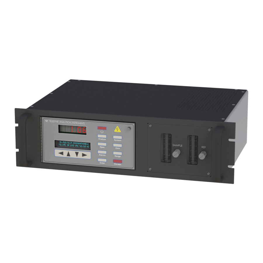
Figure 1-1. Figure 1-1 Model 2120XL Front Panel The standard 2120XL Nitrogen in Argon Analyzer is panel mounted designed for easy installation in a standard 19” instrument rack. All user controls and displays accessible from the front panel. - Page 16 Introduction Model 2120XL Function Keys: Six touch-sensitive membrane switches are used to change the specific function performed by the analyzer: Analyze Perform analysis for nitrogen content in an argon gas mixture. System Perform system-related tasks (described in detail in Chapter 4, Operation.).
-
Page 17: Rear Panel
0-1 VDC range ID, and isolated 4–20 mA DC nitrogen concentration plus 4-20 mA DC range ID. Alarm Signals: 2 concentration alarms and 1 system alarm. Remote Span/Zero Digital inputs allow external control of analyzer calibration. Teledyne Analytical Instruments... -
Page 18: Internal Components
Instrument Air Used for driving optional auto calibration valves. Figure 1-2: Model 2120XL Rear Panel 1.6 Internal Components The internal components can be accessed by removing the top cover of the analyzer. Figure 1-3 shows an inside view of the analyzer... -
Page 19: Additional Safety Information
Note: The material provided in this section contains information to promote safety in the operation and maintenance of this equipment. It is not intended to supersede, replicate, or replace any safety documentation or procedures provided from or established official safety sources. Teledyne Analytical Instruments... -
Page 20: Detector Cautions
Introduction Model 2120XL Do NOT operate the Model 2120XL Trace Nitrogen in Argon Gas Analyzer until you read and understand the operating, maintenance, and safety instructions included in this manual. Anyone involved with the operation of this equipment including plant engineering, operations, and management, must understand the potential hazards involved, and know and observe all required safety precautions. -
Page 21: Basic Safety Requirements
1.7.2 Basic Safety Requirements The following safety guidelines apply at all times when working with the Model 2120XL analyzer: Prevent electrical shock — Unplug and remove the AC power cord from the rear panel before opening and working on the analyzer. -
Page 22: Summary Of Known Hazards
Introduction Model 2120XL 1.7.4 Summary of Known Hazards This equipment is designed to minimize your exposure to the process gases and other known hazards. Read and thoroughly understand all safety aspects of this system and its operation before operating or maintaining the equipment. -
Page 23: Purging
De-pressurize supply gas piping before working on it. 1.7.4.5 G ENERAL RECAUTIONS FOR ANDLING AND TORING RESSURE YLINDERS Compressed gases have properties that can cause serious accidents, injuries, and even death if proper precautions and safety practices are Teledyne Analytical Instruments... - Page 24 Introduction Model 2120XL not followed. Therefore, during handling and use of these gases, be certain to use applicable safety precautions described by your local compressed gas supplier, the Compressed Gas Association, and/or OSHA regulations. 1. Read the label on all cylinders BEFORE using to identify the cylinder contents.
-
Page 25: Operational Theory
Operational Theory Operational Theory 2.1 The Analyzer The Model 2120XL Trace Nitrogen in Argon Gas Analyzer is a rack mounting self-contained unit for measuring trace amounts of nitrogen in an argon gas stream. A customer supplied sample system directs a stream of refined argon to the instrument at a pressure between 4 and 20 psig (14-138 kPa). -
Page 26: Sample System
The resulting emission spectra is clear and distinct. The Model 2120XL is fitted with custom optical filtering and an optics system that is specifically designed to reduce interference. The desired spectral line used for analysis is sharp and focused on the detector. - Page 27 These same conditions apply to any calibration gases used. Section 3.6.1 provides more information on a suitable sample system. If air enters the sample system, it can be removed by purging the sample lines. Recalibration is not necessary. Teledyne Analytical Instruments...
- Page 28 Operational Theory Model 2120XL Teledyne Analytical Instruments...
-
Page 29: Unpacking The Instrument
Trace Nitrogen in Argon Analyzer Installation Installation Installation of the Model 2120XL Trace Nitrogen in Argon Analyzer can involve potentially hazardous procedures. CAUTION: INSTALLATION SHOULD BE PERFORMED ONLY BY TRAINED AND QUALIFIED PERSONNEL WHO HAVE READ AND UNDERSTOOD THE INSTRUCTIONS IN THIS MANUAL. -
Page 30: Choosing A Location
GENERAL PURPOSE AREA AND IS NOT RATED FOR USE IN HAZARDOUS AREAS. 3.3 Mounting The Model 2120XL is a rack mountable unit intended for indoor use only. Space and materials required for mounting are: 8-3/4-inches (22.2 cm) of 19-inch rack space. -
Page 31: Rear Panel Connections
Figure 3-1: Required Front Door Clearance 3.4 Rear Panel Connections Figure 3-2 shows the Model 2120XL rear panel. Up to 7 gas inlet and outlet ports are installed depending on whether the unit is supplied with an optional auto calibration module. In addition, the rear panel has... -
Page 32: Electrical Connections
Installation Model 2120XL 3.5 Electrical Connections Electrical Connections are made at the rear of the instrument. See Figure 3-2. For safe connections, no uninsulated wiring should be able to come in contact with fingers, tools or clothing during normal operation. -
Page 33: Figure 3-3: Equipment Interface Connector Pin Arrangement
+ % Range, 4-20 mA, floating – % Range, 4-20 mA, floating + Range ID, 0-1 V dc – Range ID, 0-1 V dc, negative ground + % Range, 0-1 V dc – % Range, 0-1 V dc, negative ground Teledyne Analytical Instruments... -
Page 34: Table 3-2: Alarm Relay Contact Pins
Installation Model 2120XL Alarm Relays: The nine alarm-circuit connector pins connect to the internal alarm relay contacts. Each set of three pins provides one set of Form C relay contacts. Each relay has both normally open and normally closed contact connections. The contact connections are shown in Table 3-2. -
Page 35: Table 3-3: Remote Calibration Connections
Cal Contact Cal Contact Remote Calibration Protocol: To properly time the Digital Remote Cal Inputs to the Model 2120XL Analyzer, the customer's controller must monitor the Cal Relay Contact. When the contact is OPEN, the analyzer is analyzing, the Remote Cal Inputs are being polled, and a zero or span command can be sent. -
Page 36: Table 3-4: Range Id Relay Connections
If you have the Auto Caibration Option, it includes additional zero and span gas inputs— the 2120XL automatically regulates the zero, span and sample gas flow. Range ID Relays: Four dedicated Range ID relay contacts. The first three ranges are assigned to relays in ascending order—Low range is... -
Page 37: Figure 3-4: Remote Valve Connections
At this printing, this port is not yet functional. It is to be used for future options to the instrument. Pins 13 (+) and 29 (–). Remote Valve Connections: The Model 2120XL is a single-chassis instrument and does not have a Remote Probe. Instead, the Remote Probe connections are used as a method for directly controlling external sample/zero/span gas valves. -
Page 38: Rs-232 Port
Installation Model 2120XL Figure 3-5: FET Series Resistance 3.5.3 RS-232 Port The digital signal output is a standard, full duplex RS-232 serial communications port used to connect the analyzer to a computer, terminal, or other digital device. It requires a standard 9-pin D connector. -
Page 39: Gas Connections
SYSTEM. THE SAMPLE PATH MUST BE RELATIVELY FREE OF AIR AND/OR MOISTURE BEFORE APPLYING THE IONIZING VOLTAGE. KEEP THE MODEL 2120XL POWER OFF AND PURGE THE EXTERNAL TUBING. THEN APPLY POWER TO PURGE THE INTERNAL LINES. ANALYZER POWER IS NEEDED TO PURGE ANALYZER SINCE THE FLOW CONTROL MODULE NEEDS POWER TO OPERATE. - Page 40 Installation Model 2120XL Note: Air leaking into the sampling system will cause erratic or unsatisfactory analyzer operation. Even if air is admitted into the system for only a few minutes, you must purge the regulator and the system for at least 1 hour before the readings stabilize.
-
Page 41: Typical Sample System
A suggested sample system is shown in Figure 3-6. This system allows you to switch the analyzer between zero or span calibration gases and the process gas streams quickly and efficiently without disconnecting the analyzer and introducing air in the system. Figure 3-6: Suggested Sample System Teledyne Analytical Instruments... - Page 42 Use a 1/8 inch compression fitting for the analyzer inlet connection. Use a high-quality regulator or device to maintain a constant pressure to the zero, sample, and span inlet lines. Teledyne recommends using a high-purity regulator with the following specifications: ...
-
Page 43: Gas Connections To The Instrument
3.7 Purging The Model 2120XL is equipped with a flow control module installed in the analyzer sample inlet to regulate flow and pressure to the analytical cell. A maximum inlet pressure of 20 psig (138 kPa) is allowable. - Page 44 Installation Model 2120XL When installing a new analyzer or starting up an analyzer that has been idle for a period of time, the sampling system should be purged for several hours to cleanse it of contaminants and water vapor. Although high-purity sample gas may be used to purge the analyzer, argon with a minimum purity of 99.999% is recommended.
-
Page 45: Calibration
Trace Nitrogen in Argon Analyzer Installation 3.8 Calibration The Model 2120XL was calibrated at the factory in accordance with the calibration data shipped with your instrument. Prior to using the instrument for analysis the calibration must be checked using the factory settings supplied. - Page 46 Installation Model 2120XL Teledyne Analytical Instruments...
-
Page 47: Operation
Operation Operation This section describes the operation and calibration procedures for the Model 2120XL Trace Nitrogen in Argon Analyzer. Operation of the analyzer involves potentially hazardous procedures. Only trained and qualified personnel who have read and understood the instructions in this manual should operate this equipment. -
Page 48: Operation
4.2 Zero and Span Calibration The Model 2120XL is designed to provide a linear response over the 0-100 ppm concentration range for nitrogen in argon. Therefore, a two-point (zero and span) calibration is sufficient to define the calibration curve for this analyzer. -
Page 49: Setup And Operation General Information
Set alarm setpoints, and modes of alarm operation (latching, failsafe, etc). Before you configure your Model 2120XL Analyzer these default values are in effect: Ranges: LO = 1 ppm, MED = 10 ppm, HI = 100 ppm. Auto Ranging: ON Alarm Relays: Defeated, 100 and 200 ppb, HI, Not failsafe, Not latching. -
Page 50: Analyzer Functions
Operation Model 2120XL VFD screen that are not yet accepted by use of the ENTER key or to move backwards through previous screens. The VFD screen text that accompanies each operation is repro- duced, at the appropriate point in the procedure, in a Arial Narrow Bold type style. -
Page 51: System Menu
4.5.1 System Menu Dig_filt Self-test Pwd Logout Err More Autocal Flow Hold Calholdtimer More Model Out-cal Lin There are eleven sub functions within the System function as described below. Specific procedures for their use follow the descriptions. Teledyne Analytical Instruments... -
Page 52: Digital Filter
Operation Model 2120XL Dig Filt: The Model 2120XL includes a user adjustable digital filter. The filter has settings 1-10. Setting 1 is the least amount of filtering and 10 is the highest level of damping. Self–Test: The instrument performs a self-diagnostic test to ... -
Page 53: Self-Test
When the testing is complete, the results are displayed. Power: ## Analog: ## Preamp: ## The module is functioning properly if it is followed by OK. If a problem is detected, a number will appear next to the heading and Teledyne Analytical Instruments... -
Page 54: Password Protection
Operation Model 2120XL indicates a problem in a specific area of the instrument. Refer to Chapter 5 Maintenance and Troubleshooting for number-code information. The results screen alternates for a time with: Press Any Key To Continue... Then the analyzer returns to the initial System screen. - Page 55 If the password is accepted, the screen will indicate that the password restrictions have been removed and you have clearance to proceed. PSWD Restrictions Removed In a few seconds, you will be given the opportunity to change this password or keep it and go on. Teledyne Analytical Instruments...
- Page 56 Operation Model 2120XL Change Password? <ENT>=Yes <ESC>=No Press ESCAPE to move on, or proceed as in Changing the Password, below. 4.5.1.3.2 Installing or Changing the Password If you want to install a password, or change an existing password, proceed as above in Entering the Password. When you are given the...
- Page 57 Anlz AL—1 Note: If you log off the system using the logout function in the system menu, you will now be required to re-enter the password to gain access to Span, Zero, Alarm, and Range functions. Teledyne Analytical Instruments...
-
Page 58: Logout
Operation Model 2120XL 4.5.1.4 L OGOUT The Logout function provides a convenient means of leaving the analyzer in a password protected mode without having to shut the instrument off. By entering Logout, you effectively log off the instrument leaving the system protected against use until the password is reentered. -
Page 59: Auto Calibration (Auto Cal)
Note: Before setting up an AUTO-CAL, be sure you understand the Zero and Span functions as described in Section 4.5.2, and follow the precautions given there. Note: If you require highly accurate AUTO-CAL timing, use external AUTO-CAL control where possible. The internal clock in the Teledyne Analytical Instruments... - Page 60 Operation Model 2120XL Model 2120XL is accurate to 2-3 %. Accordingly, internally scheduled calibrations can vary 2-3 % per day. To setup an Auto Cal cycle: Choose SYSTEM from the function buttons. Use the ◄►arrow keys to position the blinking over the More function, and press ENTER.
-
Page 61: Flow
Track (or Hold) function, and toggle between Track or Hold using the ▲/▼ arrow keys. Press ENTER when the desired selection is indicated on the display screen. If Hold is selected, the next function sets the hold Calholdtimer period. Teledyne Analytical Instruments... -
Page 62: Calibration Hold Timer (Calholdtimer)
Operation Model 2120XL When HOLD is selected, the analog output (4-20 mA) and the range ID contacts will freeze on their last state before entering one of the calibration modes. When the instrument returns to the Analyze mode, either by a successful or an aborted calibration, there will be a three- minute delay before the analog outputs and the range ID contacts start tracking again. -
Page 63: Analog Output Calibration (Out_Cal)
Use the ▲/▼ arrow keys to adjust it up or down. When the desired value appears, Press ENTER to accept and save the value and the display automatically moves to the next line for adjusting the 20 mA setting. Use UP/DOWN arrow to Adjust 20 ma: 500 Teledyne Analytical Instruments... -
Page 64: Linearize (Lin)
Upon completion of the linearization sample introduction, the software performs linear approximation between data points. The Model 2120XL can accept up to 11 linearization points. These are: Zero point (pure argon) ... - Page 65 ENTER to accept the value. A confirmation screen will appear. <ENT> Accept <ESC> Reject Pressing ENTER again will save the data into memory to be used for calculating the coefficients used in the best fit linearization Teledyne Analytical Instruments...
-
Page 66: The Zero And Span Functions
4.5.2 The Zero and Span Functions The Model 2120XL is designed to provide a linear response over the analysis range for nitrogen in argon. Therefore, once the linearization procedure has been performed as described in 4.5.1.12 , a two-point (zero and span) calibration is sufficient to define the calibration curve . -
Page 67: Recommended Calibration Gases
A commercially available scrubber the Teledyne Part number S1748-120 (or S1748 -240 depending on AC voltage) is ideal for this. Alternatively, a zero gas cylinder with a low... - Page 68 Operation Model 2120XL Select Zero Mode : Manual (Auto) where Manual and Automatic can be toggled back and forth using the ▲/▼ arrow keys. Once the proper mode is displayed, press ENTER. The following screen appears: Zero Offset <ENT> to Begin This screen allows the user to add a zero offset if desired.
-
Page 69: Span Calibration
In the manual mode, the operator determines when the reading is are acceptably close to the actual span concentration. Make sure the span gas is connected to the instrument. See Section 3.6 for gas connections. Teledyne Analytical Instruments... - Page 70 Operation Model 2120XL After pressing the SPAN button, the mode selection screen appears: Select Span Mode : Manual (Auto) where Manual and Automatic can be toggled back and forth using the ▲/▼ arrow keys. Once the proper mode is displayed, press ENTER.
-
Page 71: The Range Function
4.5.3 The Range Function The Model 2120XL has three user programmable ranges extending from 0-1 ppm to 0-100 ppm. The Range function is used to set the three analysis ranges and to set whether the instrument functions on a fixed range (1, 2 or 3) or uses auto ranging. -
Page 72: The Alarms Function
4.5.4 The Alarms Function The Model 2120XL is equipped with 2 fully adjustable concentration alarms and one non-adjustable system alarm. Each alarm has a relay with a set of form “C" contacts rated for 3 amperes resistive load at 250 VAC. - Page 73 AL—100.0 High Dft—Y Fs—N Ltch—N Five parameters can be changed on this screen: Value of the alarm setpoint, AL–1 #### ppb/ppm (nitrogen) Out-of-range direction, HI or LO Defeated? Dft–Y/N (Yes/No) Failsafe? Fs–Y/N (Yes/No) Teledyne Analytical Instruments...
-
Page 74: The Analyze Function
ANALYZE button at any time to return to analyzing your sample. 4.7 Signal Output The standard Model 2120XL Analyzer is equipped with two 0–1 VDC analog output terminals accessible on the back panel (one concentration and one range ID), and two isolated 4–20 mA DC current outputs (one concentration and one range ID). - Page 75 They generate a steady preset voltage (or current when using the current outputs) to represent a particular range. The following table gives the range ID output for each analysis range: Range Voltage (V) Current (mA) 0.25 0.50 0.75 Teledyne Analytical Instruments...
- Page 76 Operation Model 2120XL Teledyne Analytical Instruments...
-
Page 77: Routine Maintenance
Trace Nitrogen in Argon Analyzer Maintenance Maintenance CAUTION: MAINTENANCE AND REPAIR OF THE MODEL 2120XL ANALYZER INVOLVE POTENTIALLY HAZARDOUS PROCEDURES. ONLY TRAINED AND QUALIFIED PERSONNEL WHO HAVE READ AND UNDERSTOOD THE INSTRUCTIONS IN THIS MANUAL SHOULD WORK ON THIS EQUIPMENT. -
Page 78: Fuse Replacement
Maintenance Model 2120XL Table 5-1 summarizes the recommended routine maintenance required for the Model 2120XL. Table 5-1: Routine Maintenance Schedule Maintenance Task Time Schedule Calibrate Every 1-2 weeks Check sample gas flow rate Every 1-2 weeks Check for excessive accumulation of dirt... -
Page 79: System Self Diagnostic Test
B) Sets a zero level on preamp then tests response. C) Sets a non-zero livel on preamp then tests response. Preamp is incorrect at zero level Preamp is incorrect at non-zero level Both zero and non-zero are incorrect Teledyne Analytical Instruments... -
Page 80: Error Screens
Maintenance Model 2120XL 5.5 Error Screens Additional errors are indicated by a flashing ‘E’ at the upper right corner of the analyzer display screen. If 'E' is flashing in the upper right hand corner, the instrument has detected an error. Go to menu item 'Err' and press ENTER. If there are errors, they will be listed on the screen'. -
Page 81: Sensor Replacement
If the sensor is replaced in the field, the customer must contact TAI Customer Service to obtain the required input data to linearize the new sensor. Teledyne Analytical Instruments... - Page 82 Maintenance Model 2120XL Teledyne Analytical Instruments...
-
Page 83: Appendix
Accuracy: ± 1% full scale (0-100 ppm) Alarms: Two programmable concentration alarms, and a system alarm. Relay contacts ‘C’ type Range ID contacts: Relay contacts ‘A’ type Digital Output: RS232 at 9600 baud rate, RS232 output is compatible with VB-1/VB-3 for profibus communication Teledyne Analytical Instruments... -
Page 84: Recommended Replacement Parts List
Scrubber of N2 Gas for zero cal. (240 V) F2374 Flow Control Module A85552 2120XL std. EPROM for Main PCB Note: Orders for replacement parts should include the part number (if available) and the model and serial number of the instrument for which the parts are intended. -
Page 85: Drawing List
Trace Nitrogen in Argon Analyzer Appendix A.3 Drawing List D84123 Outline Drawing C85455 Internal Piping Drawing C85454 Wiring Diagram Teledyne Analytical Instruments...