
Related Manuals for Teledyne HASTINGS 201 Series


Summary of Contents for Teledyne HASTINGS 201 Series
- Page 1 TELEDYNE HASTINGS INSTRUMENTS INSTRUCTION MANUAL 201/203/205/207 SERIES FLOW METERS/CONTROLLERS I S O 9 0 0 1 C E R T I F I E D...
- Page 2 Revision J (Document Number 141-102009A) ................October 2009 Revision K (Document Number 141-082010) ................August 2010 Revision L (Document Number 141-072011) ................... July 2011 Visit www.teledyne-hi.com for WEEE disposal guidance. The instruments described in this manual are available with multiple pin-outs. CAU TION: Ensure that all electrical connections are correct.
-
Page 3: Table Of Contents
Table of Contents GENERAL INFORMATION ............................4 1.1..................................4 EATURES 1.2. HFM-201/205 ........................... 5 PECIFICATIONS 1.3. HFC-203/207 ............................ 5 PECIFICATIONS 1.4. 4 - 20 ........................6 PTIONAL URRENT UTPUT 1.5..............................6 THER CCESSORIES INSTALLATION AND OPERATION ..........................8 2.1. -
Page 4: General Information
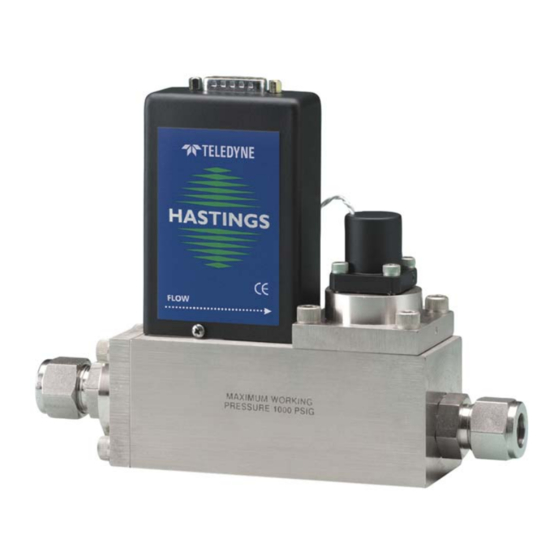
1. General Information The Hastings HFM-201/HFM-205/HFC-203/HFC-207 series Mass flow meters (HFM-201/HFM- 205) and controllers (HFC-203/HFC-207) are designed to accurately measure and control mass flow over the range of 30 slm to 2500 slm, without corrections or compensations for gas pressure and temperature with an accuracy of better than ±1% from the mean (±2% FS for 201/203 units in the ½”... -
Page 5: Specifications Hfm-201/205
1.2. Specifications HFM-201/205 Accuracy and Linearity ....................... ±1% F.S. Repeatability ........................±0.05% F.S. Standard Pressure Rating ...................... 500 psig Pressure Coefficient ............+0.0067%/psi (0 - 1000 psig N ) typical High-Pressure Option ................Proof tested to 1500 psig Leak Integrity ......................... < 1x10 sccs Temperature Coefficient ............ -
Page 6: Optional 4 - 20 Ma Current Output
1.4. Optional 4 - 20 mA Current Output An option to the standard 0 - 5 VDC output is the 4 - 20 mA current output that is proportional to flow. The 4 - 20 mA signal is produced from the 0 - 5 VDC output of the flow meter. The current loop output is useful for remote applications where pickup noise could substantially affect the stability of the voltage output or long cable runs where cable resistance would cause a voltage signal to decay. - Page 7 More information about Hastings Instruments’ power supplies can be found on the Hastings web site. http://www.teledyne-hi.com/products/powerpod-series.htm 1.5.2. Interconnecting Cables Cables are available from Hastings, in various lengths, to connect from the 15 pin "D" connector on the back of Hastings power supplies directly to any of the 200 series and 300 series flow instruments (including digital versions).
-
Page 8: Installation And Operation
2. Installation and Operation This section contains the necessary steps to get a new flow meter/controller into operation as quickly and easily as possible. Please read the following thoroughly before attempting to install the instrument. 2.1. Receiving Inspection Carefully unpack the Hastings 201/203 series instrument and any accessories that have also been ordered. -
Page 9: Mechanical Connections
2.4. Mechanical Connections The flow meter may be mounted in any position as long as the direction of gas flow through the instrument follows the arrow marked on the bottom of the flow meter case label. The preferred orientation is with the inlet and outlet fittings in a horizontal plane (if operating with a dense gas or at high pressures the instrument must be installed horizontally). -
Page 10: Operation
the ground connection at the power supply. Do not connect them together at the flow controller as the resulting crosstalk could result in flow instabilities. 24 Volt Connections Refer to the diagram at right when connecting 24 Volt units. Connect the positive lead of the power supply to pin 7 of the DE-9 connector and negative lead to pin 4. - Page 11 some zero offset.) The 201/203 series is intended for use in non-condensing environments only. Condensate or any other liquids which enter the flow meter may destroy its electronic components. 2.6.2. Zero Check Turn the power supply on if not already energized. Allow for a 1 hour warm-up. Stop all flow through the instrument and wait 2 minutes.
- Page 12 2.6.5. Operation with a Hastings power supply. There are two controls for each flow controller connected to a Hastings power supply. A switch labeled “OPEN; AUTO; CLOSED” (valve override THPS 400 only) and a potentiometer labeled “COMMAND”. For normal operation, the valve override switch will be in the “AUTO” position. The “CLOSE”...
- Page 13 2.6.7. Operation with an external sensor. (Fig. 2.2) In some instances, it might be desirable to use an external sensor to provide process information to the control circuitry in the flow controller. For example, you might want to control the pressure in a vacuum system by adjusting the rate at which the system is backfilled with a gas.
-
Page 14: Range Changing
3) Step change the command voltage to 100%, and observe the flow through the controller. If the overshoot is too large, remove the jumper. Reset the command voltage to 10%, and allow the controller to stabilize. 4) To prevent loss of the unused jumper, place it over one pin only on JP4/JP6. 2.6.9. -
Page 15: Theory Of Operation
3. Theory of Operation This section contains an overall functional description of HFC Flow Controllers. Detailed schematics and parts lists can be found at the end of the manual in Section 6.0. In this section and other sections throughout this manual, when a power supply is mentioned, it is assumed that the customer has a Hastings Power Supply. -
Page 16: Shunt
output is sent to the terminals on the back and to the decoding circuitry in the display which converts it to a 3-digit output. The controller circuitry utilizes the Command and the Flow voltages as input signals. The 0 - 5VDC command signal is subtracted from the 0 - 5VDC flow signal creating an error signal. -
Page 17: Valve
3.5. Valve: A solenoid valve is used as a pilot valve to control a much larger pneumatic diaphragm valve. The pilot valve is an “automatic metering solenoid” valve. While most solenoids operate in either the fully open or fully closed state, the automatic metering solenoid valve is designed to control flow (see Figure 3.5). -
Page 18: Maintenance
4. Maintenance This section contains service and calibration information. Some portions of the instrument are delicate. Use extreme care when servicing the flow controller. The potentiometer positions and the electrical components referred to in the troubleshooting section can be found in Section 6.0 on the electrical component layout drawing. -
Page 19: Adjustments
restriction is pneumatically close to the downstream end of the flow controller. The differential pressure across the unit must be between 10-50 psig. SYMPTOM: Little or no flow, even with Valve Override switch OPEN. CAUSE: Plugged orifice. ACTION: Verify the presence of a 10-50 psig pressure across the instrument. If present, shut off gas supply and power supply. -
Page 20: End Cap Removal
stability. If the instrument is not shutting completely off when Valve Override switch is in the CLOSE position, the orifice may require approximately 1/8 turn clockwise. 4.4. End Cap Removal: The end cap on the inlet side must be removed to gain access to the filter or shunt assembly. First shut off the supply of gas to the instrument. - Page 21 D) This formula provides approximate results that tend to be undersized because it neglects pressure drops internal to the flow controller, compressible gas effects and temperature effects. Multiply the result by ≈1.5 to get the expected minimum orifice size that can reliably pass the desired flows at the expected pressures.
- Page 22 diaphragm. Examine the o-ring on the valve top for damage if required. Install the valve top, ensuring that the ball bearing in the side is on the downstream side. Tighten down the valve top evenly to insure a proper seal at the diaphragm. Page 22 of 23 141-072011 - 201/203 Series...
-
Page 23: Warranty
If you then choose not to have the product repaired, a minimum will be charged to cover the processing and inspection. Please consult the factory for your RMA number before returning any product repair. TELEDYNE HASTINGS INSTRUMENTS 804 NEWCOMBE AVENUE HAMPTON, VIRGINIA 23669 U.S.A.