
Related Manuals for York MILLENNIUM YS


Summary of Contents for York MILLENNIUM YS
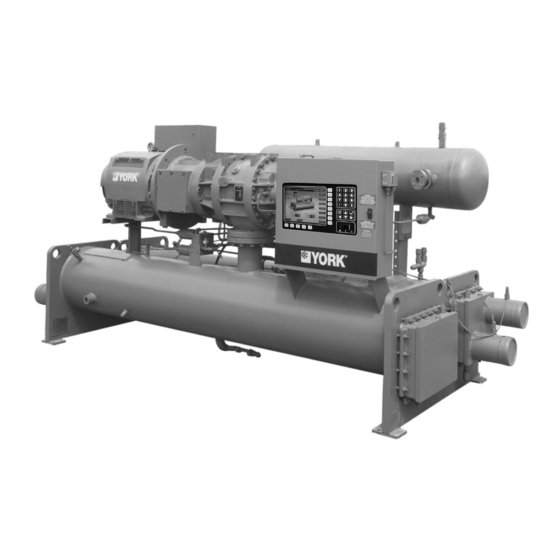
- Page 1 MILLENNIUM ® ROTARY SCREW LIQUID CHILLERS INSTALLATION, OPERATION, MAINT. Supersedes: Nothing Form 160.47-NOM3 (599) MODELS YS BA BA S0 THRU YS FC FB S5 STYLE D R-22 and R-134a 29039A(R) ® • • Metric Conversions...
-
Page 2: Nomenclature
NOMENCLATURE The model number denotes the following characteristics of the unit: – Model Special Features Cooler Code Design Level Condenser Code Motor Code Compressor Code Power Supply: – for 60 Hz 5 for 50 Hz YORK INTERNATIONAL... -
Page 3: Table Of Contents
SECTION MAINTENANCE ..............39 General ......................39 Compressor Oil .................... 39 Changing Compressor Oil................. 39 Oil Level ....................41 Oil Filter ......................41 Oil Filter Replacement ................. 41 Single Oil Filter ..................41 Dual Oil Filters ..................41 YORK INTERNATIONAL... - Page 4 Weights - English, R-22 and R-134a Units, 50 and 60 Hz ....Weights - SI, R-22 and R-134a Units, 50 and 60 Hz ......Refrigerant Relief Characteristics ............Variable Orifice Pressure Differential Setpoints ......... York Oil Types ..................Compressor Oil Limits ................ Refrigerant Charge Level ..............Water Flow Velocities .................
-
Page 5: Section 1 Installation
York representative. Refer to tory assembled unit. Form 160.47-N3.1 for detailed in- structions of Form 3 and 7 shipments. -
Page 6: Inspection
Installation list. Any material shortage should be reported to York The York Warranty will be voided if immediately. the following restrictions are not ad- hered to: DATA PLATE 1. No valves or connections should A unit data plate is mounted on the control center as- be opened under any circumstances sembly of each unit, giving unit model number;... -
Page 7: Rigging
The complete standard unit is shipped without skids. a vertical passageway, such as an el- (When optional skids are used, it may be necessary to evator shaft, contact York Factory for remove the skids so riggers skates can be used under special rigging instructions. -
Page 8: Weights - English, R-22 And R-134A Units, 50 And 60 Hz
19,893 — CB-BB 11,833 12,783 — DA-DB 18,833 20,634 — CA-CA 12,146 13,155 DB-DA 18,635 20,378 — CA-CB 12,419 13,547 DB-DB 19,153 21,119 — CB-CA 12,377 13,483 DC-DA 18,983 20,912 — CB-CB 12,650 13,874 DC-DB 19,426 21,652 — YORK INTERNATIONAL... - Page 9 2. Shipping weight includes refrigerant and oil charge. Operating weight includes water in tubes and water boxes. 3. Weights based on standard tubes in coolers and condensers. 4. Operating weight based on R-22. Subtract difference in refrigerant charge if using R-134a. YORK INTERNATIONAL...
-
Page 10: Weights - Si, R-22 And R-134A Units, 50 And 60 Hz
9,023 — CB-BB 5,367 5,798 — DA-DB 8,543 9,360 — CA-CA 5,509 5,967 DB-DA 8,453 9,243 — CA-CB 5,633 6,145 DB-DB 8,688 9,580 — CB-CA 5,614 6,116 DC-DA 8,611 9,486 — CB-CB 5,738 6,293 DC-DB 8,812 9,821 — YORK INTERNATIONAL... - Page 11 2. Shipping weight includes refrigerant and oil charge. Operating weight includes water in tubes and water boxes. 3. Weights based on standard tubes in coolers and condensers. 4. Operating weight based on R-22. Subtract difference in refrigerant charge if using R-134a. YORK INTERNATIONAL...
-
Page 12: Locating And Installing Isolator Pads
York representative. The unit should be level within 1/4 inch from one end to the other end and from front to the rear. If the chiller is... -
Page 13: Standard Neoprene Vibration Isolator Pad Mounts
FORM 160.47-NOM3 LD02942 LD02943 LD02944 OPERATING WEIGHT (Lbs. / Kgs.) DETAIL UP TO 16,365 / 7,423 16,636 / 7,546 to 28,835 / 13,080 28,836 / 13,080 to 53,530 / 24,281 FIG. 3 – STANDARD NEOPRENE VIBRATION ISOLATOR PAD MOUNTS YORK INTERNATIONAL... -
Page 14: Overall Dimensions - English, S0 Thru S3 Compressor
B – OVERALL HEIGHT 5'–8-5/8" 5'–11-1/2" 5'–10-1/4" 5'–11-1/2" 5'–11-1/4" 6'–3-1/4" 6'–3-1/4" 6'–3-1/4" 6'–7-5/8" 6'–8-3/4" 6'–9-3/8" C – COOLER C/L 1'–1-7/8" 1'–5" 1'–5" D – CONDENSER C/L 0'–11-5/8" 1'–2-1/4" 1'–2-1/4" FIG. 4 – OVERALL DIMENSIONS - ENGLISH, S0 THRU S3 COMPRESSOR YORK INTERNATIONAL... -
Page 15: Overall Dimensions - English, S4 And S5 Compressor
B – OVERALL HEIGHT 7'–9-1/8" 7'–9-1/8" 7'–9-1/8" 8'–2-1/4" 8'–2-1/4" 8'–2-1/4" C – COOLER C/L 1'–7-3/4" 1'–7-3/4" 1'–7-3/4" 1'–7-3/4" 1'–10" 1'–10" D – CONDENSER C/L 1'–5-1/4" 1'–5-1/4" 1'–5-1/4" 1'–6-1/2" 1'–5-1/4" 1'–6-1/2" FIG. 5 – OVERALL DIMENSIONS - ENGLISH, S4 AND S5 COMPRESSOR YORK INTERNATIONAL... - Page 16 1,591 1,591 1,591 B – OVERALL HEIGHT 1,816 1,895 1,857 1,899 1,848 1,946 1,946 1,946 2,054 2,102 2,102 C – COOLER C/L D – CONDENSER C/L FIG. 6 – OVERALL DIMENSIONS - STANDARD INTERNATIONAL, S0 THRU S3 COMPRESSOR YORK INTERNATIONAL...
- Page 17 – OVERALL WIDTH (Less S.S.S) 1,915 1,915 1,880 1,943 1,994 2,057 B – OVERALL HEIGHT 2,365 2,365 2,365 2,496 2,496 2,496 C – COOLER C/L D – CONDENSER C/L FIG. 7 – OVERALL DIMENSIONS - STANDARD INTERNATIONAL, S4 AND S5 COMPRESSOR YORK INTERNATIONAL...
-
Page 18: Installing Optional Spring Isolators
4,454 to 5,525 029-18479-003 S2, S3 5,526 to 6,927 029-18479-004 6,928 to 8,288 029-18480-001 8,289 to 10,392 029-18480-002 UP to 10,392 029-18480-002 S4, S5 10,392 to 11,813 029-18480-003 11,814 to 14,561 029-18480-004 FIG. 8 – SPRING ISOLATORS (OPTIONAL) YORK INTERNATIONAL... -
Page 19: Piping Connections
If the piping is annealed to relieve stress, the inside of the pipe must be cleaned of scale before it is finally bolted in place. YORK INTERNATIONAL... -
Page 20: Cooler And Condenser Water Piping
STOP VALVES as well as the pumps, tower spray nozzles, chilled water coils and controls, etc. The strainer, meeting York speci- Stop valves may be provided (by others) in the cooler fications should be installed in the entering chilled water and condenser water piping, adjacent to the unit to ease line, directly up-stream of the unit. -
Page 21: Refrigerant Relief Piping
(to maintain between 30 and ing, refer to Form 160.47-AD2. 60 ft. lbs. / 41 and 81 nm). Gasket shrinkage and handl- LD03298 FIG. 10 – TYPICAL REFRIGERANT VENT PIPING FROM RELIEF VALVES YORK INTERNATIONAL... -
Page 22: Typical Refrigerant Vent Piping From Rupture Disk
1. Piping should be properly sup- ported to prevent any strain on burst- ing disk mounting. 2. Be careful not to puncture burst- ing disk when thread protector is re- moved. LD03300 FIG. 11 – TYPICAL REFRIGERANT VENT PIPING FROM RUPTURE DISK YORK INTERNATIONAL... -
Page 23: Unit Piping
2). ASHRAE 15-1994 Section 9.8 and Appendix F describes relief requirements for positive displacement compressors. Summa rized, the unit must be equipped with a relief device suitable for relieving the entire compressor capacity. YORK YS mod D (S0 - S5 compressor) units utilize a 2" rupture disk venting to atmosphere set at 345 psid. [See note 3 for S7 units.]... -
Page 24: Unit With Solid State Starter (Optional)
Instruction, but before any attempt is made to tor Connections. (Refer to Wiring Labels in Motor Ter- start the unit, the York District Office should be advised minal Box for hook-up to suit motor voltage and amper- so that the start-up service, included in the contract price, age.) -
Page 25: Ys Motor Connections (Electro-Mechanical Starter Application)
FORM 160.47-NOM3 LD03301 FIG. 12 – YS MOTOR CONNECTIONS (ELECTRO-MECHANICAL STARTER APPLICATION) YORK INTERNATIONAL... -
Page 26: Installation Check List And Request For Authorized Start-Up Engineer
Installation LD03305 FIG. 13 – INSTALLATION CHECK LIST AND REQUEST FOR AUTHORIZED START-UP ENGINEER YORK INTERNATIONAL... -
Page 27: Section 2 Operation
When the compressor is shut off, a spring returns the slide valve to unloaded position. The com- pressor starts with the slide valve in the unloaded posi- The York YS Chiller package uses a refrigerant-flooded tion. evaporator and a liquid-cooled condenser. The compres- sor is a heavy-duty, industrial-rated rotary screw com- pressor. -
Page 28: Oil Separator
Safety Relief Control Panel Devices Compressor Oil Separator "D"-Flange Oil Filter Evaporator Isolation Valve Liquid Line Isolation Valve Fluid OUT Condenser Fluid IN FIG. 14 – COMPONENT LAYOUT DRAWING LD004303... -
Page 29: Condensing Water Temperature
ECW minimum = Minimum Entering Condensing Water Temperature ºF LCWT = Leaving Chilled Water Temperature ºF Operating below the minimum entering condensing wa- ter will not provide energy savings and will result in oil 00090VIP FIG. 17 – OIL FILTER LOCATION YORK INTERNATIONAL... -
Page 30: Oil Piping Schematic
Oil to Compressor SB - 2 Oil Port SB - 2 Oil Supply to Capacity Manifold Block Control Port "P" Oil Cooler Refrigerant Oil to Compressor Gas from Oil Port SB - 3 Cooler "OIL PRESSURE" Pressure Release Transducer "SEAL OIL PRESSURE" Valve Transducer Liquid Refrigerant... -
Page 31: Oil Pressure Transducer Location
The second stage of oil separation is accomplished by The eductor block manifold oil circuit contains the Seal directing the refrigerant gas through mesh pads that Oil Pressure Transducer and a High Oil Temperature have an extended surface area. Smaller liquid oil drop- YORK INTERNATIONAL... -
Page 32: Oil Separator Schematic
First Stage of Oil Separation Oil Out Reduction in Velocity Second Stage of Oil Separation Extended Surface Area Third Stage of Oil Separation Oil & Refrigerant Coaleser Element Gas to Eductor 1. Sight Glass 2. Oil Level Switch 3. Filter Pressure Transducer and Isolation Valve 4. -
Page 33: Oil Eductor Circuit
A small amount of oil is normal in the refrigerant charge and Do not add oil. York YS Chiller pack- will be found in the evaporator. If not properly man- ages are pre-charged with the correct... -
Page 34: Liquid Refrigerant Circuit
Table 5 for different re- charge. frigerants and EPROM version S.01F.17 and later. See York Service Bulletin 160.47-M2 (SB18) for program- HIGH PRESSURE OIL AND REFRIGERANT ming instructions. FROM OIL SEPARATOR TABLE 5 –... -
Page 35: Oil Eductor Schematic
High Pressure Oil and Refrigerant Gas from Oil Separator Suction Gas to Compressor 1. Eductor Manifold Block 2. Filter Driers 3. Service Isolation Valves High Pressure Oil and Refrigerant Gas from Oil Separator Low Pressure Oil and Refrigerant from Evaporator and Filter Driers Orifice Jet Pump Cross Section... -
Page 36: Refrigerant Schematic
Inlet Oil Oil Cooler Sub Cooled Liquid Refrigerant Liquid Refrigerant Outlet Oil to Evaporator Refrigerant Gas to Evaporator Refrigerant Charging Valve Metering Orifice Manual Isolation Valve Variable Orifice Solenoid Valve Manual Throttling Valve Manual Isolation LD04301 Valve FIG. 22 – REFRIGERANT SCHEMATIC... -
Page 37: Capacity Control
Leaving evaporator fluid temperature is continuously gain access to the service valve stem. Use a refrigera- monitored by the microprocessor. The Leaving Evapo- tion service valve wrench to close or open the valves. rator fluid temperature is compared to the Leaving YORK INTERNATIONAL... -
Page 38: Capacity Control Piping Schematic
Compressor Port SC - 1 Compressor Port SC - 2 Unload Load Compressor Port SC - 11 Unload Load Supply Oil Pressure from Manifold at SB-2 Load and Unload 4 - Way Capacity Control Solenoid Valve Sub-Plate Service Isolation Valves LD04300 FIG. -
Page 39: Section 3 Maintenance
York Service Office, this could indicate bear- ing damage and wear. York “C” Oil is a mineral oil. York “P” and “H” oil are The immersion oil heater will maintain the oil tempera- polyolester (POE) oils. Polyolester oil is very hygro- ture between 105ºF (40ºC) and 115ºF (46ºC). - Page 40 *** These procedures must be performed at the specified time interval by an Industry Certified Technician, who has been trained and qualified to work on this type of YORK equipment. A record of this procedure being successfully carried out must be maintained on file by the equipment owner, should proof of adequate maintenance be required at a later date for warranty validation purposes.
-
Page 41: Oil Level
The oil filter(s) are a replaceable 3 micron fitting, located on the top of the filter housing. Con- cartridge type oil filter. Use only York approved oil filter nect a refrigeration pressure hose to the pressure elements. See Figure 17. -
Page 42: Filter Drier Replacement
DETERMINING CORRECT REFRIGERANT CHARGE LEVEL Should it become necessary to add refrigerant charge to a York YS Chiller; add charge until the evaporator The refrigerant charge level is correct when the mea- approach and refrigerant gas discharge superheat are sured evaporator approach and discharge refrigerant at within the values listed in Table 8. -
Page 43: Refrigerant Leak Checking
York Field Service Office for the correct condenser ap- move a fitting the O-ring(s) should be replaced. Make proach. certain to use only neoprene replacement O-rings. O- rings can be ordered from the local York Service Of- CONDENSER WATER SIDE TUBE CLEANING fice. PROCEDURE... -
Page 44: Mechanical Cleaning Procedure
3. Select a tube cleaning brush for 5/8 inch I.D copper Consult the York Factory Order Form for the specific minimum condenser tubes. If tubes other than 5/8 inch copper velocity based upon the type of brine and concentration being used. -
Page 45: Vibration Analysis
Fig. 26 is pro- Note the natural or pumping frequency of the York YS vided to properly locate the transducer measurement compressor is 238 HZ at 60 HZ and 198 HZ at 50 HZ. - Page 46 SPECTRAL ALARM BANDS FOR 4/6 LOBE TWIN SCREW CHILLERS (Cont’d) (YS___S0 through S5 YORK Screw Chillers) Reference: Proven method for specifiying spectral band alarm levels and frequencies using today’s predictive main- tenance software systems James E. Berry, Technical Associates of Charlotte, Inc.
- Page 47 FORM 160.47-NOM3 This page is intentionally left blank. YORK INTERNATIONAL...
- Page 48 Proud Sponsor of the 2000 U.S. Olympic Team 36USC380 P.O. Box 1592, York, Pennsylvania USA 17405-1592 Subject to change without notice. Printed in USA Copyright © by York International Corporation 1999 ALL RIGHTS RESERVED Form 160.47-NOM3 (599) Supersedes: Nothing...