York MaxE YK Operating And Maintenance
Style f, r-134a cooling only with optiview control center
for electro-mechanical starter,
solid state starter & variable speed drive
Hide thumbs
Also See for MaxE YK:
- Installation instructions manual (28 pages) ,
- Wiring diagram (24 pages)
Table of Contents
Advertisement
Quick Links
- 1 Section 1 Description of System and Fundamentals of Operation
- 2 Section 2 System Operating Procedures
- 3 Section 3 System Components Description
- 4 Section 4 Operational Maintenance
- 5 Section 5 Troubleshooting
- 6 Section 6 Maintenance
- 7 Section 7 Preventive Maintenance
- Download this manual
See also:
Instruction and Installation Manual
Advertisement
Table of Contents

Related Manuals for York MaxE YK


Summary of Contents for York MaxE YK
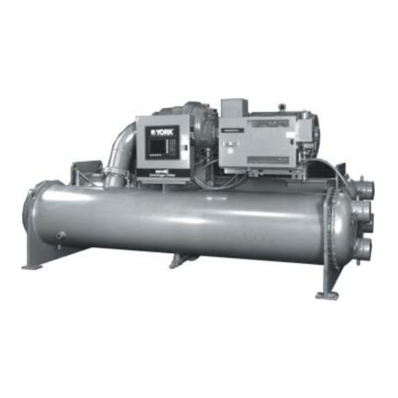
- Page 1 CENTRIFUGAL LIQUID CHILLERS OPERATING & MAINTENANCE Supersedes: 160.73-O2 (1202) Form 160.73-O2 (605) MODEL YK (STYLE F) R-134a COOLING ONLY WITH OPTIVIEW CONTROL CENTER FOR ELECTRO-MECHANICAL STARTER, SOLID STATE STARTER & VARIABLE SPEED DRIVE 00611VIP LDO5842...
- Page 2 NOT be installed inside the mi cro pan el. NO external wiring is al lowed to be run through the micro panel. All wir ing must be in ac cor dance with YORK’s pub lished spec i fi ca tions and must be per formed ONLY by qual i fi ed YORK personnel. YORK will not be re spon si ble for dam ag es/problems re sult ing from im prop er con nec tions to the con trols or ap pli ca tion of im prop er con trol sig nals.
- Page 3 While YORK ment in question. If there is any question in the mind makes no commitment to update or pro vide current...
-
Page 4: Table Of Contents
Description of System and Fundamentals of Operation ....... 6 SECTION System Operating Procedures ..............9 SECTION System Components Description ............... 15 SECTION Operational Maintenance ................21 SECTION Troubleshooting ..................23 SECTION Maintenance ....................25 SECTION Preventive Maintenance ................34 YORK INTERNATIONAL... - Page 5 FIG. 11 – EVACUATION OF CHILLER ........25 FIG. 12 – SATURATION CURVE ..........27 FIG. 13 – DIAGRAM - MEGGING MOTOR WINDINGS ..29 FIG. 14 – MOTOR STATOR TEMPERATURE & INSULATION RE SIS TANCE ......30 YORK INTERNATIONAL...
-
Page 6: Section 1 Description Of System And Fundamentals Of Operation
MAXE FIG. 1 – MODEL YK CHILLER SYSTEM OPERATION DESCRIPTION (SEE FIG. 2) electro-mechanical starter, YORK Sol id State Start er The YORK Model YK MaxE Chiller is com mon ly ap- (optional), or Variable Speed Drive (op tion al). -
Page 7: Detail A - Compressor Prerotation Vanes
fl ow of liquid re frig er ant to the evaporator to com plete the refrigerant cir cuit. YORK INTERNATIONAL... -
Page 8: Fig. 2 - Refrigerant Flow-Through Chiller
FORM 160.73-O2 (605) COM PRES SOR PREROTATION VANES (See Detail A) DISCHARGE SUCTION DIS CHARGE BAFFLE EVAPORATOR CON DENS ER ELIMINATOR SUB-COOLER FLOW CON TROL ORIFICE LD00924 OIL COOLER FIG. 2 – REFRIGERANT FLOW-THRU CHILLER YORK INTERNATIONAL... -
Page 9: Section 2 System Operating Procedures
Microcomputer Control Cen ter the pump will ter setpoints should be pro grammed before the chiller au to mat i cal ly start, therefore, this step is not neces- is started. (Refer to Form 160.54-O1). sary. YORK INTERNATIONAL... -
Page 10: Fig. 4 - Chiller Starting Sequence & Shutdown Se Quence (Em Starter & Solid State Starter)
OptiView™ Con trol Cen ter, re fer to Form 160.54-O1. LD04040 NOT FOR ALL SHUTDOWNS. REFER TO “DISPLAY MES- SAG ES” SECTION OF THIS MANUAL. FIG. 4 – CHILLER STARTING SEQUENCE & SHUT DOWN SEQUENCE (EM STARTER & SOLID STATE STARTER) YORK INTERNATIONAL... -
Page 11: Vanes
CONDENSER WATER TEMPERATURE CON TROL of the Microprocessor Board which senses the leaving chilled liquid temperature. The unit capacity will vary to The YORK MaxE chiller is designed to use less power maintain the leaving CHILLED LIQUID TEM PER A- by taking advantage of lower than design tem per a tures TURE setpoint. -
Page 12: Fig. 6 - Liquid Chiller Log Sheets
160.44-F7 and may be obtained through the near est con di tions. Condenser water tem per a tures can be YORK offi ce. Au to mat ic data logging is possible by checked on the SYSTEM Screen. connecting the optional printer and programming the 4. - Page 13 1. Leak check the entire chiller. call the near est YORK District Offi ce. Failure to re port con stant trou bles could damage the unit and in crease Quarterly the cost of repairs.
- Page 14 Open the 115 volt circuit to the Con trol Cen- the chilled water system-chilled water pump and ter. coils. Open the drains on the evaporator and condenser liquid heads to assure complete drainage. (If a Vari- YORK INTERNATIONAL...
-
Page 15: Fig. 7 - System Components
FORM 160.73-O2 (605) SECTION 3 SYSTEM COMPONENTS DE SCRIP TION OPTIVIEW CON TROL CENTER COMPRESSOR SUCTION DUAL RELIEF VALVES MOTOR EVAPORATOR 00611vip REFRIGERANT CHARGING VALVE VARIABLE SPEED OIL PUMP CON TROL SIGHT GLASS FRONT VIEW FIG. 7 – SYSTEM COMPONENTS YORK INTERNATIONAL... -
Page 16: Section 3 System Components Description
System Components De scrip tion FORM 160.73-O2 (605) DISCHARGE LINE 28778A OIL RESERVOIR PUMP OIL COOLER REAR VIEW FIG. 7 – SYSTEM COMPONENTS (CONT’D) YORK INTERNATIONAL... -
Page 17: Lubrication System
FORM 160.73-O2 (605) GENERAL 1. Compressor Drive Shaft (Low Speed) a. Shaft seal. The YORK Model YK MaxE Centrifugal Liquid b. Front and rear journal bear ings – one on each Chill er is completely factory-packaged including evapo- side of driving gear. -
Page 18: Fig. 8 - Schematic Drawing (Yk) Compressor
System Components De scrip tion FORM 160.73-O2 (605) DOUBLE BELLOWS SHAFT SEAL LOW SPEED GEAR REAR BEARING FIG. 8 – SCHEMATIC DRAWING – (YK) COM PRES SOR LUBRICATION SYSTEM LD08577 YORK INTERNATIONAL... - Page 19 The compressor motor is an open-drip-proof, squirrel ar range ments. Stub-out wa ter nozzle connections with cage, induction type constructed to YORK design spec- Victaulic grooves are weld ed to the water boxes. These i fi ca tions. 60 hertz motors operate at 3570 rpm. 50 hertz nozzle connections are suitable for Victaulic cou plings, motors operate at 2975 rpm.
- Page 20 Ad just ment of the hot gas control valve must be per- formed by a qual i fi ed service tech ni cian fol low ing the Hot Gas Set-up pro ce dure. YORK INTERNATIONAL...
-
Page 21: Section 4 Operational Maintenance
To change the dehydrator, use the following pro- con dens er-gas through the eductor. ce dure: COMPRESSOR SOLENOID VALVE CHECK VALVE OIL EDUCTOR BLOCK SOLENOID VALVE DEHYDRATOR STOP VALVE STOP VALVE LD08578 FIG. 9 – OIL RETURN SYSTEM YORK INTERNATIONAL... -
Page 22: Fig. 10 - Charging Oil Reservoir With Oil
YORK Oil Charg ing Pump When the oil reservoir is initially charged with oil, the – YORK Part No. 070-10654. To charge oil into the oil oil pump should be started manually to fi ll the lines, reservoir, proceed as follows: pas sag es, oil cooler and oil fi... -
Page 23: Section 5 Troubleshooting
S Y M P TO M : N O O I L P R E S S U R E W H E N S Y S T E M S TA R T B U T TO N P U S H E D Oil pump running in wrong Check rotation of oil pump Low oil pressure displayed on control direction. (Electrical Connections). center; compressor will not start. Troubleshoot electrical problem Oil pump not running. with oil pump VSD. YORK INTERNATIONAL... - Page 24 10. SYMPTOM: OIL PUMP FAILS TO DELIVER OIL PRESSURE No oil pressure registers when pressing Faulty oil pressure Replace oil pressure transducer. transducer OIL PRESSURE display key when oil pump runs. Faulty wiring/connectors. YORK INTERNATIONAL...
-
Page 25: Section 6 Maintenance
MAINTENANCE RENEWAL PARTS To test with R-22, proceed as follows: For any required Renewal Parts, refer to YORK Re new al 1. With no pressure in the system, charge R-22 gas into Parts Unit Components Manual 160.73-RP1. the system through the charging valve to a pres sure of 2 PSIG (14 kPa). - Page 26 Step 6 above, the leak must be sure and the evaporator head drain connection, out found and repaired. the evaporator vent connection, into the condenser YORK INTERNATIONAL...
-
Page 27: Fig. 12 - Saturation Curve
When this fi nal vaporization has taken place the pressure the re sult will be a faulty temperature reading. and temperature will continue to drop until eventually a temperature of 35°F (1.6°C) or a pres sure of 5 mm Hg. is reached. YORK INTERNATIONAL... -
Page 28: Refrigerant Charging
“Refrigerant Charging”, above. The The refrigerant charge level must be checked af ter the refrigerant lev el should be observed and the level re- pressure and temperature have equalized between the cord ed after initial charg ing. YORK INTERNATIONAL... -
Page 29: Fig. 13 - Diagram - Megging Motor Windings
(See Fig. 13); these read ings are to be interpreted using the graph shown 24 hours of idle stand by. in Fig. 14. LD00475 FIG. 13 – DIAGRAM, MEGGING MOTOR WIND INGS YORK INTERNATIONAL... -
Page 30: Fig. 14 - Motor Stator Temperature & Insulation Re Sis Tance
Maintenance FORM 160.73-O2 (605) LD00476 TEMPERATURE – °F FIG. 14 – MOTOR STARTER TEMPERATURE AND INSULATION RE SIS TANC ES YORK INTERNATIONAL... - Page 31 These symp toms may also be due to foul gas buildup. Purging will re move the te nance pro grams to elim i nate future foul gas revealing the effect of fouling. prob lems. YORK INTERNATIONAL...
- Page 32 Pres- and condensers. If acid cleaning is required, YORK surize the dry system with 50 to 100 PSIG (345 to rec om mends the use of this type of organization. The 690 kPa) of nitrogen.
- Page 33 fi lter is installed, notify the nearest YORK offi ce to by restricted oil lines, passages, or dirty oil fi l ters. If the re quest the presence of a YORK Service Tech ni cian.
-
Page 34: Section 7 Preventive Maintenance
IM POR TANT – If a unit failure occurs due (See Table 4) to improper maintenance during the war ran ty pe ri od; YORK will not be liable for costs in curred to re turn the Frame Standard... - Page 35 2. It is important that the factory settings of controls (operation and safety) not be changed. If the set tings The use of untreated water in cooling towers, closed are changed without YORK’s approval, the warranty water systems, etc. frequently results in one or more of will be jeopardized.
- Page 36 SI METRIC CONVERSION P.O. Box 1592, York, Pennsylvania USA 17405-1592 Tele. 800-861-1001 Subject to change without notice. Printed in USA Copyright © by YORK International Corporation 2005 www.york.com ALL RIGHTS RESERVED Form 160.73-O2 (605) Supersedes: 160.73-O2 (1202)