Table of Contents
Advertisement
Advertisement
Table of Contents

Related Manuals for York MaxE YK


Summary of Contents for York MaxE YK
- Page 1 CENTRIFUGAL LIQUID CHILLERS INSTALLATION INSTRUCTIONS Supersedes: 160.73-N1 (1102) Form 160.73-N1 (904) MODEL YK (STYLE F) R-134a (COOLING ONLY) WITH OPTIVIEW™ CONTROL CENTER FOR ELECTRO-MECHANICAL STARTER, SOLID STATE STARTER & VARIABLE SPEED DRIVE 00611VIP LD05842...
- Page 2 XA, XB, XC, XD DA – DJ 5DA – 5OJ NOMENCLATURE — Spe cial Mod i fi ca tions Model Design Level Evaporator Code Motor Code Condenser Code Power Supply – for 60 Hz Compressor Code 5 for 50 Hz YORK INTERNATIONAL...
- Page 3 In complying with YORK’s policy for continuous product improvement, the information contained in this document is subject to change without notice. While YORK makes no commitment to update or provide current information automatically to the manual owner, that information, if applicable, can be obtained by contacting the nearest YORK Applied Systems Service offi...
-
Page 4: Table Of Contents
Fig. 12 – Spring Isolators (Metric) ..............Fig. 13 – Schematic for a Typical Piping Arrangement........Fig. 14 – Typical Refrigerant Vent Piping ............Fig. 15 – Control Panel Positioning ..............Fig. 16 – Motor Connections (E.M. Starter)............ YORK INTERNATIONAL... -
Page 5: Fig. 1 - Model Yk Maxe™ Chiller
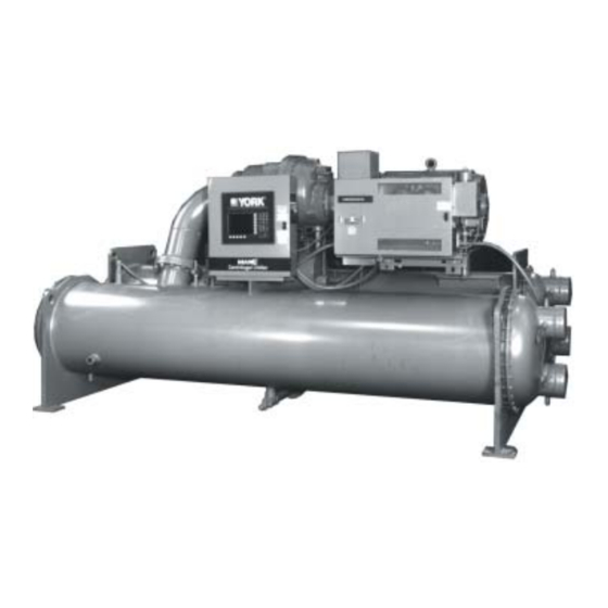
FORM 160.73-N1 (904) COMPRESSOR MOTOR OPTIVIEW™ CONTROL CENTER CONDENSER EVAPORATOR 00611VIP FIG. 1 – MODEL YK MaxE™ CHILLER YORK INTERNATIONAL... -
Page 6: Dimensions
3. Water nozzles can be located on either end of unit. Add 1/2" (13 mm) to nozzle length for fl anges connections. 4. To determine overall height, add 7/8" (22 mm) for isolators. 5. Use of motors with motor hoods may increase overall unit di men sions. FIG. 2 – DIMENSIONS – P COMPRESSOR UNITS (FT.–IN.) YORK INTERNATIONAL... -
Page 7: Fig. 3 - Dimensions (P Compressors - Metric)
3. Water nozzles can be located on either end of unit. Add 13 mm (1/2 inch) to nozzle length for fl anges connections. 4. To determine overall height, add 22 mm (7/8 inch) for isolators. 5. Use of motors with motor hoods may increase overall unit di men sions. FIG. 3 – DIMENSIONS – P COMPRESSOR UNITS (mm) YORK INTERNATIONAL... -
Page 8: Fig. 4 - Dimensions (H Compressors - Ft.-In.)
3. Water nozzles can be located on either end of unit. Add 1/2" (13 mm) to nozzle length for fl anges connections. 4. To determine overall height, add 7/8" (22 mm) for isolators. 5. Use of motors with motor hoods may increase overall unit di men sions. FIG. 4 – DIMENSIONS – H COMPRESSOR UNITS (FT.–IN.) YORK INTERNATIONAL... -
Page 9: Fig. 5 - Dimensions (H Compressors - Metric)
3. Water nozzles can be located on either end of unit. Add 13 mm (1/2 inch) to nozzle length for fl anges connections. 4. To determine overall height, add 22 mm (7/8 inch) for isolators. 5. Use of motors with motor hoods may increase overall unit di men sions. FIG. 5 – DIMENSIONS – H COMPRESSOR UNITS (mm) YORK INTERNATIONAL... -
Page 10: Fig. 6 - Dimensions (J Compressors - Ft.-In.)
3. Water nozzles can be located on either end of unit. Add 1/2" (13 mm) to nozzle length for fl anges connections. 4. To determine overall height, add 7/8" (22 mm) for isolators. 5. Use of motors with motor hoods may increase overall unit di men sions. FIG. 6 – DIMENSIONS – J COMPRESSOR UNITS (FT.–IN.) YORK INTERNATIONAL... - Page 11 1'–2" 1'–6-1/4" 1'–7-5/8" 1'–7-5/8" 1'–10-1/8" 1'–7-5/8" 1'–2" 2'–0-1/4" 1'–7-5/8" 1'–7-5/8" 1'–10-1/8" 1'–7-5/8" LD10115 3 PASS CONDENSERS DIM. 1'–2" 1'–4-7/8" 1'–7" 1'–7" 1'–7-3/4" 1'–7-5/8" 1'–2" 1'–8-1/8" 1'–10-1/8" 1'–10-1/8" 1'–11-3/8" 1'–7-5/8" FIG. 6 (CON'T) – DIMENSIONS – J COMPRESSOR UNITS YORK INTERNATIONAL...
-
Page 12: Fig. 7 - Dimensions (J Compressors - Metric)
3. Water nozzles can be located on either end of unit. Add 13 mm (1/2 inch) to nozzle length for fl anges connections. 4. To determine overall height, add 22 mm ( 7/8 inch) for isolators. 5. Use of motors with motor hoods may increase overall unit di men sions. FIG. 7 – DIMENSIONS – J COMPRESSOR UNITS (mm) YORK INTERNATIONAL... - Page 13 FORM 160.73-N1 (904) Dimensions (mm) 1 PASS CONDENSERS DIM. 2 PASS CONDENSERS DIM. LD10115 3 PASS CONDENSERS DIM. FIG. 7 (CON'T) – DIMENSIONS – J COMPRESSOR UNITS YORK INTERNATIONAL...
-
Page 14: Chiller Weights
3,995 J3, J4 43,775 56,340 3,995 J3, J4 47,450 61,620 4,290 J3, J4 44,885 57,915 3,820 J3, J4 48,565 63,215 4,150 J3, J4 53,230 69,610 4,460 67,100 86,760 5,810 * Refer to product drawings for detailed weight information. YORK INTERNATIONAL... -
Page 15: Motor Weights
1,815 J3, J4 19,855 25,560 1,815 J3, J4 21,525 27,950 1,950 J3, J4 20,360 26,270 1,736 J3, J4 22,030 28,675 1,886 J3, J4 24,145 31,575 2,027 30,430 39,350 2,635 * Refer to product drawings for detailed weight information. YORK INTERNATIONAL... -
Page 16: Introduction
3. When units are shipped dismantled, notify the Form 3 – Driveline Separate From Shells – Shipped near est YORK offi ce in ample time for a YORK as two major assemblies. Unit fi rst factory rep re sen ta tive to supervise rigging the unit... -
Page 17: Inspection - Damage - Shortage
Any material shortage should be reported to YORK as sem bled by, or under the su per vi sion im me di ate ly. (Refer to Shipping Damage Claims, Form of, a YORK rep re sen ta tive. (See Form 50.15-NM) 160.73-N3) CHILLER DATA PLATE Form 7 –... -
Page 18: Location
40°F to 110°F (4.4°C to 43.3°C). LOCATION MOTORS YORK MaxE™ Chillers are furnished with vi bra tion The YK open motor is air cooled. Check state, local and iso la tor mounts for basement or ground lev el in stal la tions. -
Page 19: Isolators
CONDENSOR CENTERLINE CENTERLINE SHELLS CENTERLINE SHELLS CENTERLINE SHEET SHEET END SHEET END SHEET COOLER COOLER CENTERLINE CENTERLINE * See Fig. 2, 4, or 6 See Fig. 2, 4, or 6 FIG. 9 – NEOPRENE ISOLATORS (STANDARD DIMENSIONS) LD10114 YORK INTERNATIONAL... -
Page 20: Fig. 10 - Neoprene Isolators (Metric)
CONDENSOR CENTERLINE CENTERLINE SHELLS CENTERLINE SHELLS CENTERLINE SHEET SHEET END SHEET END SHEET COOLER COOLER CENTERLINE CENTERLINE * See Fig. 3, 5, or 7 See Fig. 3, 5, or 7 LD10117 FIG. 10 – NEOPRENE ISOLATORS (METRIC DIMENSIONS) YORK INTERNATIONAL... -
Page 21: Fig. 11 - Spring Isolators (Ft.-In.)
13 ½" BOLT ½" *See Fig. 2, 4, or 6 ACOUSTICAL 8" See Fig. 2, 4, or 6 NONSKID NEOPRENE PAD LD10119 14" 11" UNIT WEIGHT 89,341 LBS. UP TO 115,000 LBS. FIG. 11 – SPRING ISOLATORS (STANDARD DIMENSIONS) YORK INTERNATIONAL... -
Page 22: Fig. 12 - Spring Isolators (Metric)
*See Fig. 3, 5, or 7 13 mm ACOUSTICAL 203 mm See Fig. 3, 5, or 7 NONSKID NEOPRENE PAD LD10118 356 mm 280 mm UNIT WEIGHT 40,252 Kgs. UP TO 52,164 Kgs. FIG.12 – SPRING ISOLATORS (METRIC DIMENSIONS) YORK INTERNATIONAL... -
Page 23: Installation
- cap screw(s) through the hole(s) in the mounting bracket vi sion of a YORK rep re sen ta tive. into the tapped hole in the top of the isolator leveling bolt(s). -
Page 24: Evaporator And Condenser Water Piping
fl ushed before being connected to the chiller to or slightly higher than the required minimum. Refer pumps, or other equipment. to Fig. 13 for typical water pip ing schematic. EVAP O RA TOR LD08529 FIG. 13 – SCHEMATIC OF A TYPICAL PIPING ARRANGEMENT YORK INTERNATIONAL... -
Page 25: Refrigerant Relief Piping
30 and 60 ft. lbs. (41 and 81 N·m) the nuts on be com plet ed under the supervision of the YORK the liquid head fl ang es. Gasket shrinkage and han dling rep re sen ta tive: (1) the lubricant piping to oil sump and dur ing tran sit cause nuts to loosen. -
Page 26: Control Panel Positioning
YORK representative. a phase se quence in di ca tor in the pres- ence of the YORK rep re sen ta tive. POWER WIRING DO NOT cut wires to final length Chiller with Electro-Mechanical Starter or make fi... -
Page 27: Insulation
Instruction, but before any attempt is made to start of the YORK rep re sen ta tive. the unit, the YORK District Offi ce should be ad vised so that the start-up service, included in the con tract price, can be sched uled. - Page 28 Tele. 800-861-1001 P.O. Box 1592, York, Pennsylvania USA 17405-1592 Subject to change without notice. Printed in USA www.york.com Copyright © by York International Corporation 2004 ALL RIGHTS RESERVED Form 160.73-N1 (904) Supersedes: 160.73-N1 (1102)