Table of Contents
Advertisement
Quick Links
Advertisement
Table of Contents

Related Manuals for Datalogic DSE0420


Summary of Contents for Datalogic DSE0420
- Page 1 DSE0420 Area Imager Decoded Scan Engine Integration Guide...
- Page 2 Datalogic representative. Electronic versions may either be downloadable from the Datalogic website (www.datalogic.com) or provided on appropriate media. If you visit our website and would like to make comments or suggestions about this or other Datalogic publi- cations, please let us know via the "Contact Datalogic" page.
-
Page 3: Table Of Contents
PREFACE ........................................V About this Manual ........................................v Manual Conventions ....................................v Outline ..........................................v Technical Support ........................................vi Datalogic Website Support .................................... vi Reseller Technical Support .................................... vi Telephone Technical Support ..................................vi MECHANICAL CHARACTERISTICS ................................1 Overview ............................................ 1 Key Parameters ....................................... - Page 4 NOTES DSE0420...
-
Page 5: Integrator Software License Agreement
Agreement. If you use the Datalogic Product, you will be deemed to have accepted the terms and conditions of this Agreement. If you do not intend to be bound to the terms of this Agreement, Datalogic is not willing to license the Software to you, you may not use the Datalogic Product or the Software, and you must contact the party from whom you acquired the Datalogic Product for instructions. - Page 6 In the defense or settlement of any such claim, Datalogic may, at its option, 1) procure for Integrator the right to continue using the Datalogic Product, 2) modify the Datalogic Product so that it becomes non-...
-
Page 7: Preface
Preface About this Manual This Integration Guide is provided to give instruction, opto-mechanical details, and design considerations to integrate the DSE0420 model (desig- nated as “scan engine” or “OEM scan engine” in this manual) specifically into equipment-integrated scanning applications. Manual Conventions... -
Page 8: Technical Support
Telephone Technical Support If you do not have internet or email access, you may contact Datalogic tech- nical support at (541) 349-8283 or check the back cover of your manual for more contact information. -
Page 9: Mechanical Characteristics
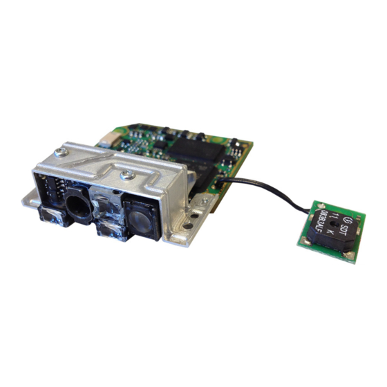
Chapter 1 Mechanical Characteristics Overview DSE0420 SCAN ENGINE Imager module Decoder board Host connector Aim projector Receiving optics Microprocessor Illuminator Beeper connector Beeper board Green Spot projector (*) cable is shown for reference only, it is not included in the assembly and must be provided by the integrator... -
Page 10: Key Parameters
(*) cable is shown for reference only, it is not included in the assembly and must be provided by the integrator Key Parameters Parameter Value Weight (DSE0420) 20 g Max Height (Beeper board not included) 13.65 mm Max Width (Beeper board not included) 40.10 mm... -
Page 11: Optical Characteristics
Chapter 2 Optical Characteristics Key Parameters Parameter Value Optical Format 1/3-inch 4.51mm(H) x 2.88mm(V) Active Imager Size 5.35mm diagonal Active Pixels 752H x 480V LED source Illumination System White emission (wavelength = 400-750 nm) IEC 62471 – EXEMPT RISK GROUP Laser source Red emission (wavelength = 630-680 nm) Aiming System... -
Page 12: Illumination System
Figure 1. Projected pattern at 200 mm Aiming System Parameters Wavelength 630-680 nm 35° (horizontal) x 25° (vertical) – see drawings on Beam Divergence page 25 Maximum pulse duration 15ms Repetition rate 16.6ms Maximum output power page 25 Laser aperture See drawings on DSE0420... -
Page 13: Regulatory
Key Parameters Regulatory • EN/IEC 60825-1:2007 (class 2) • 21 CFR 1040 (CDRH) (class II) Viewing the laser output with certain optical instruments (for example, eye loupes, magnifiers, and microscopes) within a dis- tance of 100mm may pose an eye hazard. WARNING . -
Page 14: Reading Performances
Pitch angle = 10° • Skew angle = 0° • Tilt angle = 10° (1D labels) – 0° (2D labels) Figure 3. Side view Scan Pitch Tilt Engine 10° 10° Distance . Top view Figure 4 Target Distance Skew 0° DSE0420... -
Page 15: Exit Window Recommendations
Key Parameters Exit Window Recommendations The use of a double-sided AR coated exit window is strongly rec- ommended. Avoiding scratched windows Scratches on the exit window can strongly affect the reading performance. It is recommended to use an exit window having a scratch-resistant coating and to position the engine window in a recessed position. - Page 16 Optical Characteristics NOTES DSE0420...
-
Page 17: Electrical Integration
Chapter 3 Electrical Integration Overview = 25° C (unless otherwise noted) PARA- TEST CONDITIONS UNIT METER Input Voltage Shut down μA = 0 V POWER_ON In-rush current at Start-up 3.25 First peak after plug-in Duration of In-rush current at Start-up μs In-rush charge at Start-up μC... -
Page 18: Host Connector Configuration
External power supply 5V +/- 5%, electrically shorted VBUS to Pin #6 0V reference, electrically shorted to Pin #1 USB D- Data N, USB differential pair USB D+ Data P, USB differential pair 0V reference, electrically shorted to Pin #4 DSE0420... -
Page 19: Hw_Trigger Signal
Overview Description: • POWER_ON signal can be used by host to switch-on/off the whole Scan Engine: leave it unconnected if not used • HW_TRIGGER signal can be used to physically • issue a “trigger pressure” event to the Scan Engine: leave it uncon- nected if not used •... - Page 20 Electrical Integration NOTES DSE0420...
-
Page 21: Software Features
USB-COM driver and how it relates to the two interfaces: The DL USB-COM driver is supplied by Datalogic, and provides legacy appli- cations the ability to connect to a ‘virtual’ COM port enumerated by the device during connection to the PC. -
Page 22: Firmware And Configuration Updates
5204h Update with Aladdin 4. The Datalogic USB-COM driver will be provided for inclusion in the host’s image; there will be no need for users to install the driver on the host. Any subsequent updates that may become available will be han- dled through the software update process, if needed. - Page 23 C:\<path> cfirmwareupdate <scanner_name> <”path:file- name”> Where: <path> = the location on the tablet where the Datalogic utilities are installed <scanner_name> = IntegratedImagingBarcodeScanner <”path:filename”> = the path to the update file+update file name 3.
- Page 24 Software Features NOTES DSE0420...
-
Page 25: Quality And Reliability
Chapter 5 Quality and Reliability Test ID Test Description Dynamic Shock: 2000 G ± 5% applied via any mounting surface at -30º C and 70º C for a period of 0.85 ± 0.05 msec. 2500 G ± 5% applied via any mounting surface at 23º C for a period of 0.85 ± 0.05 msec Shock Vibration:... - Page 26 Quality and Reliability NOTES DSE0420...
-
Page 27: Regulatory & Safety
Chapter 6 Regulatory & Safety Item Description IEC 60825 – CLASS 2 LASER PRODUCT Laser Classification Maximum emitted power: 1 mW, Emitted wavelength 630-680 nm Pulsed source: maximum lamp duration 15ms, repetition rate 16.6 ms Lamp Standard IEC 62471 Exempt Radiated Emissions EN 55022 / 2010 Support documentation is available on request to assist the ODM in their sys-... - Page 28 Regulatory & Safety NOTES DSE0420...
-
Page 29: Mtbf Prediction (Calculated)
Appendix A MTBF Prediction (Calculated) Product: DSE0420 System MTBF: DSE0420 MTBF Operating Temperature Operating Temperature Duty Cycle 25ºC 55ºC 100% 218,412 hrs. 60,125 hrs. 399,416 hrs. 109,785 hrs. DSE0420 RAMM Operating Temperature Operating Temperature Duty Cycle 25ºC 55ºC 100% 0.00334 0.01214... -
Page 30: System Model
• All Electronic assembly failure rates calculated from BOM listing using Telcordia model. DATALOGIC HAS DEMONSTRATED A 99% SUCCESS RATE OF MEETING OR EXCEEDING OUR PREDICTION BASED ON ACTUAL PRODUCT DEMONSTRATED LIFE TEST RESULTS AND ACTUAL FIELD DATA. Any requests for reliability information on our products are granted with a clear understanding that MTBF/RAMM numbers are design targets. -
Page 31: Mechanical Drawings
Appendix B Mechanical Drawings This section describes the main mechanical features related to the following key points: • Overall Dimensions • Optical features • Exit Window Positioning Interface Connector Characteristics & Requirements • Integration Guide... -
Page 32: Overall Dimensions
Overall Dimensions DSE0420... -
Page 33: Optical Features
Optical features Integration Guide... -
Page 34: Exit Window Positioning
Exit Window Positioning For additional information about the Scan Engine, please refer to the DE2011-DL Integration Guide DSE0420... -
Page 35: Interface Connector Characteristics & Requirements
Interface Connector Characteristics & Requirements Integration Guide... - Page 36 NOTES DSE0420...
- Page 38 ©2014 Datalogic, Inc. All rights reserved. Datalogic and the Datalogic logo are registered trademarks of Datalogic S.p.A. in many countries, including the U.S.A. and the E.U. Datalogic ADC, Inc. 959 Terry Street Eugene |OR 97402 Telephone: (1) 541-683-5700 Fax: (1) 541-345-7140...