Table of Contents
Advertisement
Advertisement
Table of Contents

Related Manuals for Datalogic DSE0421


Summary of Contents for Datalogic DSE0421
- Page 1 DSE0421, DSE0451 Area Imager Decoded Scan Engine Integration Guide...
- Page 2 All rights reserved. Without limiting the rights under copyright, no part of this documenta- tion may be reproduced, stored in or introduced into a retrieval system, or transmitted in any form or by any means, or for any purpose, without the express written permission of Datalogic S.p.A. and/or its affiliates.
-
Page 3: Table Of Contents
Assembly Calculation Criteria: ................................28 MECHANICAL DRAWINGS ..................................29 DSE0421-DSE0451 Overall Dimensions ............................30 DSE0421-DSE0451 Optical features ..............................31 DSE0421-DSE0451 Interface Connectors Characteristics and Requirements ................32 DSE0421-DSE0451_R Overall Dimensions ............................33 DSE0421-DSE0451_R Optical features ..............................34 DSE0421-DSE0451_R Interface Connector Characteristics and Requirements ................35 Integration Guide... - Page 4 DBC0421-DBC0451Interface Adapters ..............................36 Exit Window Positioning ..................................37 Six Positions Cable with Connector ..............................38 Six Positions Cable with Connector ..............................39 DSE0421, DSE0451...
- Page 5 THE SOFTWARE AND THE END USER IS NOT ALLOWED TO DOWNLOAD, INSTALL OR USE THE SOFTWARE OR THE DATALOGIC PRODUCT This End User License Agreement ("EULA") is between Datalogic IP Tech S.r.l. having its registered office at Via San Vitalino 13, 40012 Calderara di Reno (Bologna), Italy ("Datalogic"), and you, either an individual or a single entity, ("End User or "You"") who has purchased one or more DSE0421 or DSE0451 ("Datalogic Product") subject to the...
- Page 6 Data and Computer Software clause at DFARS 252.227-7013(c)(1)(ii), whichever is applicable. If End User is using the Datalogic Product outside of the United States, End User must comply with the applicable local laws of the country in which the Datalogic Product is used and with U.S.
- Page 7 Italian Court of Bologna shall have exclusive jurisdiction over all matters regarding this Agreement, except that Datalogic shall have the right, at its absolute discretion, to initiate proceedings in the courts of any other state, coun- try, or territory in which End User resides, or in which any of End User's assets are located.
- Page 8 NOTES DSE0421, DSE0451...
-
Page 9: Preface
Preface About this Manual This Integration Guide is provided to give instruction, opto-mechanical details, and design considerations to integrate the DSE0421 and DSE0451 (designated as “scan engine” or “OEM scan engine” in this manual) specifi- cally into equipment-integrated scanning applications. -
Page 10: Technical Support
Telephone Technical Support If you do not have internet or email access, you may contact Datalogic tech- nical support at (541) 349-8283 or check the back cover of your manual for more contact information. -
Page 11: Introduction
USB (model DSE0421) or on a full UART interface (model DSE0451). The DSE04X1 products have also the possibility to place the reading head (camera + illuminator + aimer) in a different location with respect to the decoder board (-R models). -
Page 12: Mechanical Characteristics
Introduction Mechanical Characteristics Overview DSE0421 / DSE0451 DSE0421-R / DSE0451-R Buzzer/LED Buzzer/LED Peripherals’ Cable Peripherals’ Cable Scan Engine Scan Engine Decoder Decoder Host Connection* Host Connection* Scan Engine Scan Engine Buzzer Buzzer Decoder Decoder Green Spot Green Spot Scan Engine... -
Page 13: Key Parameters
Mechanical Characteristics Key Parameters Parameter Value Weight 20 g Max Height (Beeper board not included) 13.65 mm Max Width (Beeper board not included) 40.10 mm Max Length (Beeper board not included) 47.86 mm Dimensions Mechanical Drawings, starting on page 29 for further details on mechanical features. - Page 14 Introduction NOTES DSE0421, DSE0451...
-
Page 15: Optical Characteristics
Chapter 2 Optical Characteristics Key Parameters Parameter Value Optical Format 1/3-inch 4.51mm(H) x 2.88mm(V) Active Imager Size 5.35mm diagonal Active Pixels 752H x 480V LED source Illumination System White emission (wavelength = 400-750 nm) IEC 62471 – EXEMPT RISK GROUP Laser source Red emission (wavelength = 630-680 nm) Pulsed source: maximum lamp duration 15ms, repetition rate... -
Page 16: Illumination System
Aiming System Parameters Parameter Value Wavelength 630-680 nm 35° (horizontal) x 25° (vertical) – see drawings on Beam Divergence page 31 Maximum pulse duration 15ms Repetition rate 16.6ms Maximum output power page 31 Laser aperture See drawings on DSE0421, DSE0451... -
Page 17: Regulatory
Key Parameters Regulatory • EN/IEC 60825-1:2007 (class 2) • 21 CFR 1040 (CDRH) (class II) Viewing the laser output with certain optical instruments (for example, eye loupes, magnifiers, and microscopes) within a dis- tance of 100mm may pose an eye hazard. WARNING . -
Page 18: Reading Performances
“in open air” means without any interposed transparent or semi-trans- parent material • environmental light = 300 lux • Pitch angle = 10° • Skew angle = 0° • Tilt angle = 10° (1D labels) – 0° (2D labels) Figure 3. Performance Test Conditions DSE0421, DSE0451... -
Page 19: Exit Window Recommendations
Key Parameters Exit Window Recommendations The use of a double-sided AR coated exit window is strongly rec- ommended. Avoiding scratched windows Scratches on the exit window can strongly affect the reading performance. It is recommended to use an exit window having a scratch-resistant coating and to position the engine window in a recessed position. - Page 20 Optical Characteristics NOTES DSE0421, DSE0451...
-
Page 21: Electrical Integration
Chapter 3 Electrical Integration Overview = 25° C (unless otherwise noted) PARA- TEST CONDITIONS UNIT METER Input Voltage Shut down μA = 0 V POWER_ON In-rush current at Start-up 3.25 First peak after plug-in Duration of In-rush current at Start-up μs In-rush charge at Start-up μC... -
Page 22: Host Connector (8 Pins)
J2 connector is indicated by the red box: Figure 4 - Top View The following drawing illustrates the way to insert the flat cable (not included in the assembly) into the ZIF connector (Host Port): DSE0421, DSE0451... - Page 23 Host Connector (8 pins) Here the list of pins with related functions explained follows: Signal Name Dir. Description Notes Connected to BJT-Base with the following net: Used to power up the sys- tem: a High POWER_ON logical level allows the system to boot ...
- Page 24 Standard USB DP line pair Transmit Data line for UART, TTL logic USB D+ or UART TXD A 220 Ohm series resistor is mounted GND or RTS 0V reference in USB models only, shorted to pin #4 DSE0421, DSE0451...
-
Page 25: Peripherals' Connector (6 Pins)
Peripherals' Connector (6 Pins) Peripherals' Connector (6 Pins) The Peripherals' port is used to drive the buzzer (if present) and/or the Green Spot LED (if present). The buzzer and/or the Green Spot LED send a feed-back after a good decoding, after the issuing of a command, or for general signaling. - Page 26 Pin 1 connected to the Beeper positive pin and to the White LED’s anode pin 150 mA MAX drained current (not continuous) Pin 2 Negative pin of the beeper BEEPER_NEG used to inject Pin 1 the sound wave DSE0421, DSE0451...
-
Page 27: Hw_Trigger Signal
HW_TRIGGER Signal HW_TRIGGER Signal This paragraph describes different ways to drive the HW_TRIGGER signal in order to instruct the Decoder to start acquisition & decode process. Each of these Scan Modes must be first issued (programmed) to the Decoder before to use it. -
Page 28: Interface Adapters
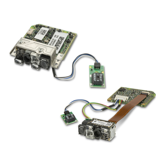
(USB or UART). The figure below shows an example of how to connect the Decoder board (in this case DSE0421 and DSE0451) to a host PC: Figure 6 - USB/RS232 Connections USB Connection... - Page 29 Interface Adapters As illustrated in the Figure 6, it is possible to connect a push button to the Interface Adapter to allow an external trigger signal to be sent to the Decoder board. Such a connection must be carefully designed to avoid ESD (electrical discharges) to reach the Interface Adapter and/or the Decoder board.
- Page 30 Electrical Integration NOTES DSE0421, DSE0451...
-
Page 31: Software Features
USB-COM driver and how it relates to the two interfaces: The DL USB-COM driver is supplied by Datalogic, and provides legacy appli- cations the ability to connect to a ‘virtual’ COM port enumerated by the device during connection to the PC. -
Page 32: Firmware And Configuration Updates
5204h with Aladdin 4. The Datalogic USB-COM driver will be provided for inclusion in the host’s image; there will be no need for users to install the driver on the host. Any subsequent updates that may become available will be han- dled through the software update process, if needed. -
Page 33: Quality And Reliability
Chapter 5 Quality and Reliability Test ID Test Description Dynamic Shock: 2000 G ± 5% applied to the Scan Engine surface at -30º C and 70º C for a period of 0.85 ± 0.05 msec. 2500 G ± 5% applied to the Scan Engine surface at 23º C for a period of 0.85 ±... - Page 34 Quality and Reliability NOTES DSE0421, DSE0451...
-
Page 35: Regulatory & Safety
Chapter 6 Regulatory & Safety Item Description IEC 60825 – CLASS 2 LASER PRODUCT Laser Classification Maximum emitted power: 1 mW, Emitted wavelength 630-680 nm Pulsed source: maximum lamp duration 15ms, repetition rate 16.6 ms Lamp Standard IEC 62471 Exempt Radiated Emissions EN 55022 / 2010 Support documentation is available on request to assist the ODM in their sys-... - Page 36 Regulatory & Safety NOTES DSE0421, DSE0451...
-
Page 37: Mtbf Prediction (Calculated)
Appendix A MTBF Prediction (Calculated) Product: DSE04X1 DSE0421-R MTBF Operating Temperature Operating Temperature Duty Cycle 25ºC 55ºC 100% 147,926 39,085 276,286 73,172 System RAMM: DSE0421-R RAMM Operating Temperature Operating Temperature Duty Cycle 25ºC 55ºC 100% 0.00493 0.01868 0.00264 0.00998 Calculation Method: •... -
Page 38: Assembly Calculation Criteria
• All Electronic assembly failure rates calculated from BOM listing using Telcordia model. DATALOGIC HAS DEMONSTRATED A 99% SUCCESS RATE OF MEETING OR EXCEEDING OUR PREDICTION BASED ON ACTUAL PRODUCT DEMONSTRATED LIFE TEST RESULTS AND ACTUAL FIELD DATA. Any requests for reliability information on our products are granted with a clear understanding that MTBF/RAMM numbers are design targets. -
Page 39: Mechanical Drawings
This section describes the main mechanical features related to the following key points: • DSE0421-DSE0451 Overall Dimensions • DSE0421-DSE0451 Optical features • DSE0421-DSE0451 Interface Connectors Characteristics and Requirements • DSE0421-DSE0451_R Overall Dimensions • DSE0421-DSE0451_R Optical features • DSE0421-DSE0451_R Interface Connector Characteristics and Requirements •... -
Page 40: Dse0421-Dse0451 Overall Dimensions
DSE0421-DSE0451 Overall Dimensions DSE0421, DSE0451... -
Page 41: Dse0421-Dse0451 Optical Features
DSE0421-DSE0451 Optical features Integration Guide... -
Page 42: Dse0421-Dse0451 Interface Connectors Characteristics And Requirements
DSE0421-DSE0451 Interface Connectors Characteristics and Requirements DSE0421, DSE0451... -
Page 43: Dse0421-Dse0451_R Overall Dimensions
DSE0421-DSE0451_R Overall Dimensions Integration Guide... -
Page 44: Dse0421-Dse0451_R Optical Features
DSE0421-DSE0451_R Optical features DSE0421, DSE0451... -
Page 45: Dse0421-Dse0451_R Interface Connector Characteristics And Requirements
DSE0421-DSE0451_R Interface Connector Characteristics and Requirements Integration Guide... -
Page 46: Dbc0421-Dbc0451Interface Adapters
PCB UART USB Interface Adapter for micro-USB RS232 Interface Adapter for EIA<->TTL converison* 40.6 21.6 18.8 12.3 10.3 FASTENER KEEPOUT FASTENER KEEPOUT 12.5 21.8 (*) a standard Datalogic RS232 cable must be used to connect to host PC DSE0421, DSE0451... -
Page 47: Exit Window Positioning
Exit Window Positioning For additional information about the Scan Engine, please refer to the DE2011-DL Integration Guide Integration Guide... -
Page 48: Six Positions Cable With Connector
Six Positions Cable with Connector DSE0421, DSE0451... -
Page 49: Six Positions Cable With Connector
Six Positions Cable with Connector Integration Guide... - Page 50 NOTES DSE0421, DSE0451...
- Page 52 Datalogic and the Datalogic logo are registered trademarks of Datalogic S.p.A. in many countries, including the U.S.A. and the E.U. Touch is a trademark of Datalogic S.p.A. and/or its affiliates, registered in the U.S. Datalogic USA, Inc. 959 Terry Street | Eugene, OR 97402 |USA...