Advertisement
Quick Links
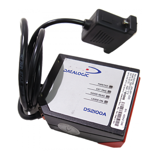
1
Mounting Holes
2
Laser On LED
3
Good Read LED
4
External Trigger LED
For further details on product installation, see the
complete Installation Manual.
DS2100A can be configured through the WinHost
Windows-based software program available on the
installation CD-ROM.
For configuration it is necessary to create a cable
connecting the scanner to the PC as indicated in the
"How To Build A Simple Interface Test Cable" section of
this guide.
POWER SUPPLY
- This product is intended to be installed by Qualified
Personnel only.
- All Models:
This accessory device is intended to be supplied by a UL
Listed or CSA Certified Power Unit with «Class 2» or LPS
power source which supplies power directly to the
scanner via the 25-pin connector.
DS2100A
Laser Barcode Reader
Quick Reference Guide
1
2
3
6
Figure A
Power On / Data TX LED
5
Warning and Device Class Labels
6
Accessory Mounting Holes
7
Laser Beam Output Window
8
The scanner is classified as a Class 2 laser
product according to EN 60825-1 regulations
and as a Class II laser product according to
4
CDRH regulations.
5
Disconnect the power supply when opening the
device during maintenance or installation to
avoid exposure to hazardous laser light.
There is a safety device which allows the laser to
be switched on only if the motor is rotating above
the threshold for its correct scanning speed.
The laser beam can be switched off through a
software command (see also the WinHost Help
On Line).
7
N2468
8
218441
C
Warning and Device Class Labels
The laser diode used in this device is
classified as a class 3B laser product
according to EN 60825-1 regulations and as a
Class IIIb laser product according to CDRH
regulations. As it is not possible to apply a
classification label on the laser diode used in
this device, the following label is reproduced
below.
EMITTED WAVE LENGTH 630~680 nm
Laser Diode Class Label
Any violation of the optic parts in particular
can cause radiation up to the maximum level
of the laser diode (35 mW at 630 to 680 nm).
LASER LIGHT
DO NOT STARE INTO BEAM
CLASS 2 LASER PRODUCT
MAX. OUTPUT RADIATION 1 mW
EMITTED WAVE LENGTH 630~680 nm
TO EN 60825-1:2001
CAUTION-CLASS 3B LASER LIGHT
WHEN OPEN AVOID EXPOSURE TO BEAM
This product conforms to the applicable
requirements of 21CFR1040 at the date
R
of manufacture.
US
LASER LIGHT
AVOID EXPOSURE TO BEAM
CLASS 3B LASER PRODUCT
MAX. OUTPUT RADIATION 35 mW
TO EN 60825-1 (2001)
Advertisement

Related Manuals for Datalogic DS2100A


Summary of Contents for Datalogic DS2100A
- Page 1 Installation Manual. Class IIIb laser product according to CDRH regulations. As it is not possible to apply a DS2100A can be configured through the WinHost classification label on the laser diode used in Windows-based software program available on the this device, the following label is reproduced installation CD-ROM.
- Page 2 DS2100A QUICK GUIDE Model Description: DS2100A - X X X X Optical Resolution Communication Interface Optic Version Performance 1 = Standard resolution 0 = Linear 0 = Standard 2= RS232/RS485main + RS232 aux 2 = High resolution 1 = Raster R1 4 = Testarossa ™...
- Page 3 93ACC1727, 93ACC1728 Electrical Connections: DS2100A is equipped with a cable terminated by a 25-pin female D-sub connector for connection to the power supply and input/output signals. You can bring system cables directly to the 25-pin connector or you can connect the scanner directly to one of the various C-Box models and bring system wiring to it (see the relative C-Box Installation Manual).
- Page 4 EXT TRIG+ 8/11 OUT REF EXT TRIG- 12/22 Signal Ground Output open collector connections Input NPN command using DS2100A power INPUT PNP max = 40 Vdc Vext 30 Vdc max. EXTERNAL TRIGGER DS2100A I max = 40 mA continuous + 5V...
- Page 5 DS2100A QUICK GUIDE Connectivity: RS232 Main Interface Connections RS485 Main Interface Connections RS232 Point-to-point layout RS485 Point-to-point layout DS2100A DS2100A DS2100A Terminal Host Terminal Terminal Host Host Main Serial Interface (RS232) Main Serial Interface (RS485 Full Duplex) Auxiliary Serial Interface (Local Echo) (RS232)
- Page 6 DS2100A QUICK GUIDE Reading Diagrams: DS2100A-1200 (Standard Resolution, 500 scans/s) (in) (mm) 80 100 120 140 160 180 200 220 240 260 CONDITIONS Optic Version = Linear Code = Interleaved 2/5 or Code 39 0.35 mm ≥ 0.50 mm PCS = 0.90 0.20 mm...
- Page 7 DS2100A QUICK GUIDE DS2100A-2200 (High resolution, 500 scans/s) (in) (mm) 20 30 90 100 110 120 130 CONDITIONS ≥ 0.30 mm (12 mils) Optic Version = Linear Code = Interleaved 2/5 or Code 39 PCS = 0.90 0.15 mm Pitch angle = 0°...
- Page 8 Standard - for 0.50 mm (20 mils) codes and greater *Code Reading Condition = Standard * Parameter selectable in Winhost (mm) (in) DS2100A-2204 Testarossa™ - (High Resolution, 1000 scans/s) (in) (m m ) 90 100 110 120 130 CONDITIONS Optic Version = Linear Code = Interleaved 2/5 or Code 39 PCS = 0.90...
- Page 9 The following wiring diagrams show a simple test cable including power, external (push-button) trigger and PC RS232 COM port connections. 25-pin D-sub male 9-pin D-sub female TXAUX RXAUX SGND DS2100A EXT TRIG+ EXT TRIG- Power Supply VS (10 – 30 Vdc) Power GND Trigger Test Cable for DS2100A...
- Page 10 Bologna - Italy dichiara che declares that the déclare que le bescheinigt, daß das Gerät declare que el DS2100A-XXXX Laser Scanner e tutti i suoi modelli and all its models et tous ses modèles und seine modelle y todos sus modelos...