Datalogic DS2100N Reference Manual
Laser
Hide thumbs
Also See for DS2100N:
- Quick reference manual (20 pages) ,
- Brochure & specs (2 pages) ,
- Reference manual (106 pages)
Table of Contents
Advertisement
Advertisement
Table of Contents

Related Manuals for Datalogic DS2100N


Summary of Contents for Datalogic DS2100N
- Page 1 DS2100N Reference Manual...
- Page 2 DS2100N Reference Manual Ed.: 06/2013 © 2007 – 2013 Datalogic Automation S.r.l. ALL RIGHTS RESERVED. Protected to the fullest extent under U.S. and international laws. Copying, or altering of this document is prohibited without express written consent from Datalogic Automation S.r.l.
-
Page 3: Table Of Contents
INSTALLATION ......................24 Package Contents ......................24 Mechanical Installation ....................25 3.2.1 Mounting DS2100N ....................26 3.2.2 Mounting a GFC-2020 Accessory Lateral Output Deflection Mirror ......27 3.2.3 Mounting a GFC-2100 Accessory Lateral Output Deflection Mirror ......28 3.2.4 Mounting a GFC-200 Accessory Contact Reading Mirror .......... 29 3.2.5 Mounting an OM2000N Accessory Oscillating Mirror .......... - Page 4 4.3.2 ID-NET™ Response Time ..................43 4.3.3 ID-NET™ Network Termination .................. 47 Auxiliary RS232 Interface ...................47 Inputs .......................... 48 4.5.1 Code Verifier.......................51 Outputs ........................51 User Interface - Host....................53 25-PIN CABLE ELECTRICAL CONNECTIONS ............54 Power Supply......................55 Main Serial Interface....................55 5.2.1 RS232 Interface......................56 5.2.2 RS485 Full-Duplex Interface..................57 5.2.3 RS485 Half-Duplex Interface ..................
-
Page 5: References
Genius™ Help On Line SUPPORT THROUGH THE WEBSITE Datalogic provides several services as well as technical support through its website. Log on to www.datalogic.com and click on the Industrial Automation links for further information: Products - Industrial Automation - Identification Select your product from the links on the Identification page. -
Page 6: Safety And Compliance Notices
LASER SAFETY The following information is provided to comply with the rules imposed by international authorities and refers to the correct use of the DS2100N scanner. Standard Regulations This scanner utilizes a low-power laser diode. Although staring directly at the laser beam momentarily causes no known biological damage, avoid staring at the beam as one would with any very strong light source, such as the sun. -
Page 7: Fcc Compliance
FCC COMPLIANCE Modifications or changes to this equipment without the expressed written approval of Datalogic could void the authority to use the equipment. This device complies with PART 15 of the FCC Rules. Operation is subject to the following two conditions: (1) This device may not cause harmful interference, and (2) this device must accept any interference received, including interference which may cause undesired operation. -
Page 8: Ce Compliance
HANDLING The DS2100N is designed to be used in an industrial environment and is built to withstand vibration and shock when correctly installed, however it is also a precision product and therefore before and during installation it must be handled correctly to avoid damage. - Page 9 do not fine tune the positioning by striking the scanner or bracket. do not weld the scanner into position which can cause electrostatic, heat or output window damage. do not spray paint near the scanner which can cause output window damage.
-
Page 10: General View
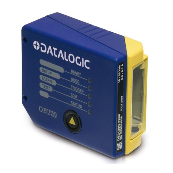
GENERAL VIEW DS2100N Figure A Laser Beam Output Window Warning and Device Class Labels "COM" LED "POWER ON" LED "STATUS" LED Mounting Holes "READY" LED Push Button "GOOD" LED Accessory Mounting Holes "TRIGGER" LED... -
Page 11: Rapid Configuration
When On-Line Operating mode is used, the scanner is activated by an External Trigger (photoelectric sensor) when the object enters its reading zone. PG 6000 MAIN DS2100N CBX100/500 Host * Presence Sensor I/O, AUX P.S. (for On-Line mode) Figure 1 – DS2100N in Stand Alone Layout... - Page 12 DS2100N REFERENCE MANUAL CBX100/500 Pinout for DS2100N The table below gives the pinout of the CBX100/500 terminal block connectors. Use this pinout when the DS2100N reader is connected by means of the CBX100/500: CBX100/500 Terminal Block Connectors Input Power Outputs...
- Page 13 25-pin Connector Pinout for DS2100N The table below gives the pinout of the 25-pin male D-sub connector for connection to the power supply and input/output signals. Use this pinout when the DS2100N reader is connected by means of the 25-pin connector:...
-
Page 14: Step 2 - Mounting And Positioning The System
DS2100N REFERENCE MANUAL STEP 2 – MOUNTING AND POSITIONING THE SYSTEM 1. To mount the DS2100N, use the mounting bracket to obtain the most suitable position for the reader as shown in the figures below. Skew Tilt Pitch Skew Figure 3 - Positioning with Mounting Bracket 2. -
Page 15: Step 3 - X-Press™ Configuration
RAPID CONFIGURATION STEP 3 – X-PRESS™ CONFIGURATION X-PRESS™ is the intuitive Human Machine Interface designed to improve ease of installation and maintenance. Status and diagnostic information are clearly presented by means of the five colored LEDs, whereas the single push button gives immediate access to the following relevant functions: AutoSetup to self-optimize and auto-configure ... -
Page 16: Auto Learn
DS2100N REFERENCE MANUAL Auto Learn If you are configuring your scanner using X-PRESS™, you must start with the Auto Learn procedure. 1. Enter the Auto Learn function by holding the X-PRESS™ push button pressed until the LEARN LED is on. - Page 17 RAPID CONFIGURATION Auto Setup (Optional) At the end of the Auto Learn procedure, you have the possibility to follow the Auto Setup procedure to set up the reading parameters. 1. Enter the Auto Setup function by holding the X-PRESS™ push button pressed until the SETUP LED is on.
-
Page 18: Step 4 - Installing Genius™ Configuration Program
DS2100N REFERENCE MANUAL STEP 4 – INSTALLING GENIUS™ CONFIGURATION PROGRAM ™ Genius is a Datalogic scanner configuration tool providing several important advantages: Wizard approach for new users; Multi-language version; Defined configuration directly stored in the reader; Communication protocol independent from the physical interface allowing to consider the reader as a remote object to be configured and monitored. - Page 19 RAPID CONFIGURATION 1. Select the Create a new configuration button. You will be guided through the configuration being asked to define the following parameters: Barcode selection and definition...
- Page 20 DS2100N REFERENCE MANUAL Operating mode selection and definition Digital Outputs configuration...
- Page 21 RAPID CONFIGURATION Hardware interface selection Output data format configuration The On Line operating Mode requires the reader to be connected to an External Trigger/Presence Sensor using I1A and I1B inputs. The Automatic operating mode does not require connection to an external Presence Sensor.
- Page 22 DS2100N REFERENCE MANUAL 2. After defining the parameter values the following window appears allowing to complete the reader configuration as follows: Saving the configuration to disk; Switching to Advanced mode; Sending the configuration to the scanner. 3. After sending the configuration to the 4.
-
Page 23: Step 5 - Test Mode
STEP 5 – TEST MODE Use a code suitable to your application to test the system. Alternatively, you can use the Datalogic Test Chart (Code 39, Code Interleaved 2/5). 1. Enter the Test mode function by holding the X-PRESS™ push button pressed until the TEST LED is on. -
Page 24: Advanced Scanner Configuration
interconnection. ID-NET™ is in addition to the Main and Auxiliary serial interfaces. If you need to install an ID-NET™ network refer to this DS2100N Reference Manual. The scanner can also be configured for alternative layouts by reading programming barcodes. See the "Setup Procedure Using Programming Barcodes" printable from the CD-ROM. -
Page 25: Introduction
2 INTRODUCTION 2.1 PRODUCT DESCRIPTION The DS2100N laser scanner satisfies the most advanced needs of a wide range of users. It has been developed focusing on the realistic requirements of its target market. The outstanding result is an extremely compact, cost-effective and easy to use industrial scanner. -
Page 26: Indicators
DS2100N REFERENCE MANUAL 2.1.1 Indicators The five LEDs on the side of the scanner (Figure A) indicate the following: This LED indicates the device is ready to operate. READY (green) This LED confirms successful reading. GOOD (green) This LED indicates the status of the reading phase. *... - Page 27 INTRODUCTION ID-NET™ M/S Multidata: Multiple stations – single scanner CBX100 CBX100 CBX100 ID-NET™ interface allows connection of scanners reading objects placed on independent conveyors. All scanners are typically located far away from each other and they use a dedicated presence sensor. At the end of each reading phase, each scanner transmits its own data message to the host.
-
Page 28: How To Setup/Configure The Scanner Network
DS2100N REFERENCE MANUAL 2.2.1 How To Setup/Configure the Scanner Network A complete ID-NET™ scanner network can be rapidly setup, as follows: Mounting & Connection 1. Mechanically mount/install all the readers (refer to par. 3.2 and 3.2.4). 2. Wire ID-NET™ (refer to par. 4.3 or 5.3). -
Page 29: X-Press™ Human Machine Interface
INTRODUCTION 2.3 X-PRESS™ HUMAN MACHINE INTERFACE X-PRESS™ is the intuitive Human Machine Interface designed with the precise goal of improving ease of installation and maintenance. Status and diagnostic information are clearly presented by means of five-colored LEDs, whereas the single multi-function key gives immediate access to relevant functions: Autosetup to self-optimize reading performance... -
Page 30: X-Press™ Functions
DS2100N REFERENCE MANUAL 2.3.2 X-PRESS™ Functions READY Quick access to the following functions is provided by an easy procedure using the push button: GOOD SETUP 1 – Press the button (the STATUS LED will give a TRIGGER visual feedback). LEARN 2 –... - Page 31 INTRODUCTION AutoLearn Function Once entered, the reader starts a procedure to automatically detect and recognize barcodes (by type and length), which are presented to it . The laser turns on and the LEARN LED blinks to indicate the ongoing process. The procedure is as follows: place the desired barcode on the scanline.
-
Page 32: Model Description
Environmental parameters are reset, all LEDs blink simultaneously 3 times and the message "Default Set" is shown on the display. 2.4 MODEL DESCRIPTION The DS2100N scanner is available in versions that differ in regard to the following parameters: Resolution ... -
Page 33: Accessories
INTRODUCTION 2.5 ACCESSORIES The following accessories are available on request for the DS2100N: Name Description Part Number Mirrors GFC-200 85° Contact Reading Mirror 93A201108 GFC-2100 2KN 90° Lateral Output Window 93A201000 GFC-2020 2KN 102° Lateral Output Mirror 93ACC1871 OM2000N Oscillating Mirror... -
Page 34: Installation
DS2100N REFERENCE MANUAL 3 INSTALLATION 3.1 PACKAGE CONTENTS Verify that the DS2100N reader and all the parts supplied with the equipment are present and intact when opening the packaging; the list of parts includes: DS2100N reader with cable DS2100N Quick Guide ... -
Page 35: Mechanical Installation
INSTALLATION 3.2 MECHANICAL INSTALLATION DS2100N can be installed to operate in different positions. The four screw holes (M4 x 5) on the body of the reader are for mechanical fixture (Figure A, 3). The diagrams below give the overall dimensions of the scanner and mounting bracket and may be used for installation. -
Page 36: Mounting Ds2100N
DS2100N REFERENCE MANUAL 3.2.1 Mounting DS2100N Using the DS2100N mounting bracket you can obtain the most suitable position for the reader as shown in the figure below: Tilt Skew Skew Pitch Figure 14 – Positioning with Mounting Bracket... -
Page 37: Mounting A Gfc-2020 Accessory Lateral Output Deflection Mirror
INSTALLATION 3.2.2 Mounting a GFC-2020 Accessory Lateral Output Deflection Mirror The GFC-2020 accessory is a 102° Lateral Output deflection mirror which helps to position the scanner body in a different orientation with respect to the code, for limited space applications. The installation of the deflection mirror is very easy. -
Page 38: Mounting A Gfc-2100 Accessory Lateral Output Deflection Mirror
DS2100N REFERENCE MANUAL 3.2.3 Mounting a GFC-2100 Accessory Lateral Output Deflection Mirror The GFC-2100 accessory is a 90° Lateral Output deflection mirror which helps to position the scanner body in a different orientation with respect to the code, for limited space applications. -
Page 39: Mounting A Gfc-200 Accessory Contact Reading Mirror
3.2.4 Mounting a GFC-200 Accessory Contact Reading Mirror The GFC-200 is an 85° contact reading mirror that is mounted directly to the DS2100N Scanner. The GFC-200 allows contact reading, eliminating the external optical path. Figure 23 - GFC-200 General View The overall dimensions are provided in the figure below and can be used for proper installation. - Page 40 DS2100N REFERENCE MANUAL To fix a DS2100N Scanner to the GFC-200, use the two M 4 x 6 mm screws supplied with the GFC Kit. Refer to the following figure. Figure 25 - Fixing DS2X00N Scanner to GFC-200 The GFC-200 85° contact reading mirror assures that the minimum skew angle is maintained to avoid direct light reflection which can degrade reading performance.
- Page 41 The internal optical path from the scanner reading window to the GFC-200 window is 51 mm. The reading distance of the DS2100N scanner with the GFC-200 is shifted by 51 mm towards the scanner because of the internal optical path between the scanner and the GFC- 200 output window.
-
Page 42: Mounting An Om2000N Accessory Oscillating Mirror
(see Figure 30). It therefore operates exclusively at low power, between 10 and 30 VDC. The following figure gives the overall dimensions of the DS2100N + OM2000N and may be used for its installation in the application. - Page 43 INSTALLATION The installation of the deflection mirror is very easy. 1) Clean the OM2000N mirror surface and output window (internally and externally) with a clean soft cloth and alcohol before assembling it to the scanner. All abrasive substances must be absolutely avoided as they cause irreparable damage to the transparency of the glass.
- Page 44 DS2100N REFERENCE MANUAL The reading distance of the scanner with the OM2000N is shifted by 10 mm towards the scanner because of the internal optical path between the scanner and the OM2000N output window. The reading performance also decreases in typical conditions by about 10% due to the optical signal passing through the output window of the OM2000N and the reflection on the mirror surface.
-
Page 45: Positioning
INSTALLATION 3.3 POSITIONING The DS2100N scanner is able to decode moving barcode labels at a variety of angles, however significant angular distortion may degrade reading performance. When mounting the DS2100N take into consideration these three ideal label position angles: Skew 10° to 30°, Tilt 0° and Pitch 0°. -
Page 46: Cbx Electrical Connections
DS2100N REFERENCE MANUAL 4 CBX ELECTRICAL CONNECTIONS All DS2100N models are equipped with a cable terminated by a 25-pin male D-sub connector for connection to the power supply and input/output signals. We recommend making system connections through one of the CBX connection boxes since they offer the advantages of easy connection, easy device replacement and filtered reference signals. -
Page 47: Power Supply
CBX ELECTRICAL CONNECTIONS To avoid electromagnetic interference when the scanner is connected to a CBX connection box, verify the jumper positions in the CBX as indicated in its Installation Manual. NOTE 4.1 POWER SUPPLY Power can be supplied to the scanner through the CBX100/500 spring clamp terminal pins as shown in Figure 38: Power Supply VGND... -
Page 48: Rs232 Interface
IDLE IDLE Figure 40 - RS232 Control Signals If the RTS/CTS handshaking protocol is enabled, the DS2100N activates the RTS output to indicate a message is to be transmitted. The receiving unit activates the CTS input to enable the transmission. -
Page 49: Rs485 Full-Duplex Interface
CBX ELECTRICAL CONNECTIONS 4.2.2 RS485 Full-Duplex Interface The RS485 full-duplex (5 wires + shield) interface is used for non-polled communication protocols in point-to-point connections over longer distances (max 1200 m / 3940 ft) than those acceptable for RS232 communications or in electrically noisy environments. The CBX pinout follows: CBX100/500 Function... -
Page 50: Rs485 Half-Duplex Interface
The RS485 half-duplex (3 wires + shield) interface is used for polled communication protocols. It can be used for Multidrop connections with a Datalogic Multiplexer, (see par. 6.5) exploiting a proprietary protocol based on polled mode called MUX32 protocol, where a master device polls slave devices to collect data. - Page 51 RS485 HD Termination Resistor. PG-6000 Earth Figure 44 - DS2100N Multidrop Connection to a Multiplexer * When using CBX500, the Main interface multidrop network signals: Shield, SGND, RTX+and RTX- are repeated on terminal connector row 4 to facilitate system cabling.
-
Page 52: Id-Net™ Interface
1200 m 900 m 700 m * Application dependent, contact your Datalogic Automation representative for details. The default ID-NET™ baudrate is 500 kbps. Lower ID-NET™ baudrates allow longer cable lengths. The baudrate is software configurable by authorized Datalogic Automation personnel only. -
Page 53: Id-Net™ Response Time
CBX ELECTRICAL CONNECTIONS 4.3.2 ID-NET™ Response Time The following figure shows the response time of the ID-NET™ network. This time is defined as the period between the Trigger activation and the beginning of data transmission to the Host. Max ID-NET™ Response Time 14 15 Number of Nodes 500 kbps... - Page 54 DS2100N REFERENCE MANUAL Figure 46 – ID-NET™ Network Connections with isolated power blocks...
- Page 55 CBX ELECTRICAL CONNECTIONS Figure 47 - ID-NET™ Network Connections with Common Power Branch Network...
- Page 56 DS2100N REFERENCE MANUAL Figure 48 – ID-NET™ Network Connections with Common Power Star Network...
-
Page 57: Id-Net™ Network Termination
CBX ELECTRICAL CONNECTIONS 4.3.3 ID-NET™ Network Termination The network must be properly terminated in the first and last scanner of the network. This is done by setting the ID-NET™ Termination Resistance Switch in the CBX100/500 to ON. 4.4 AUXILIARY RS232 INTERFACE The auxiliary serial interface is used exclusively for RS232 point-to-point connections. -
Page 58: Inputs
This input is optocoupled and can be driven by both an NPN and PNP type command. The connections are indicated in the following diagrams: EXTERNAL TRIGGER INPUT CONNECTIONS USING DS2100N POWER PH-1 Photocell (PNP) (brown) (black) (blue) Figure 51 – PH-1 (PNP) External Trigger Using DS2100N Power... - Page 59 NPN Photocell Power to Input Photocell Signal Photocell Reference Figure 52 - NPN External Trigger Using DS2100N Power EXTERNAL TRIGGER INPUT CONNECTIONS USING EXTERNAL POWER PNP Photocell Input Signal Pulled down to External Input Device Reference Figure 53 - PNP External Trigger Using External Power...
- Page 60 DS2100N REFERENCE MANUAL CBX100/500 Function Power Source - Inputs Input 2 A (polarity insensitive) Input 2 B (polarity insensitive) Power Reference - Inputs INPUT 2 CONNECTIONS USING DS2100N POWER Input Device Power to Input Device Input Input Device Signal Reference...
-
Page 61: Code Verifier
Figure 56 - NPN Input 2 Using External Power 4.5.1 Code Verifier If the DS2100N is used as a Code Verifier, the verifier code can be configured in software through the Genius™ configuration program. However it is also possible to use one of the inputs to trigger when the scanner should store a code read as the verifier code. - Page 62 OUTPUT CONNECTIONS USING DS2100N POWER Output Device Power to Output Output device Signal Output device Reference Figure 57 - Open Emitter Output Using DS2100N Power Output Device Power to Output device Output device Reference Output Signal Figure 58 - Open Collector Output Using DS2100N Power...
-
Page 63: User Interface - Host
CBX ELECTRICAL CONNECTIONS 4.7 USER INTERFACE - HOST The following table contains the pinout for standard RS232 PC Host interface. For other user interface types please refer to their own manual. RS232 PC-side connections 9-pin male connector 25-pin male connector Name Name... -
Page 64: 25-Pin Cable Electrical Connections
DS2100N REFERENCE MANUAL 5 25-PIN CABLE ELECTRICAL CONNECTIONS All DS2100N models are equipped with a cable terminated by a 25-pin male D-sub connector for connection to the power supply and input/output signals. The details of the connector pins are indicated in the following table. -
Page 65: Power Supply
5.2 MAIN SERIAL INTERFACE The signals relative to the following serial interface types are available on the input/output connector of DS2100N. If the interface type is not compatible with the current communication handshaking, then the system forces the handshake to none. -
Page 66: Rs232 Interface
IDLE IDLE Figure 64 - RS232 Control Signals If the RTS/CTS handshaking protocol is enabled, the DS2100N activates the RTS output to indicate a message is to be transmitted. The receiving unit activates the CTS input to enable the transmission. -
Page 67: Rs485 Full-Duplex Interface
Function RS485 Transmit Data + RS485 Receive Data + RS485 Transmit Data - RS485 Receive Data - Ground DS2100N USER INTERFACE RX485 TX485 Chassis Figure 65 - RS485 Full-duplex Connections For applications that do not use RX signals, do not leave these lines floating but connect them to GND as shown below. -
Page 68: Rs485 Half-Duplex Interface
The RS485 half-duplex (3 wires + shield) interface is used for polled communication protocols. It can be used for Multidrop connections with a Datalogic Multiplexer, (see par. 6.5) exploiting a proprietary protocol based on polled mode called MUX32 protocol, where a master device polls slave devices to collect data. - Page 69 25-PIN CABLE ELECTRICAL CONNECTIONS Figure 68 - DS2100N Multidrop Connection to a Multiplexer...
-
Page 70: Id-Net™ Interface
1200 m 900 m 700 m * Application dependent, contact your Datalogic Automation representative for details. The default ID-NET™ baudrate is 500 kbps. Lower ID-NET™ baudrates allow longer cable lengths. The baudrate is software configurable by authorized Datalogic Automation personnel only. -
Page 71: Id-Net™ Response Time
25-PIN CABLE ELECTRICAL CONNECTIONS 5.3.2 ID-NET™ Response Time The following figure shows the response time of the ID-NET™ network. This time is defined as the period between the Trigger activation and the beginning of data transmission to the Host. Max ID-NET™ Response Time 14 15 Number of Nodes 500 kbps... - Page 72 DS2100N REFERENCE MANUAL Figure 70 – ID-NET™ Network Connections with isolated power blocks...
- Page 73 25-PIN CABLE ELECTRICAL CONNECTIONS Figure 71 - ID-NET™ Network Connections with Common Power Branch Network...
- Page 74 DS2100N REFERENCE MANUAL Figure 72 – ID-NET™ Network Connections with Common Power Star Network...
-
Page 75: Id-Net™ Network Termination
Genius™ based Host Mode Programming installed from the CD-ROM. The following pins of the 25-pin connector are used to connect the RS232 auxiliary interface: Name Function Receive Data Transmit Data Ground DS2100N USER INTERFACE Chassis Figure 73 - RS232 Auxiliary Interface Connections... -
Page 76: Inputs
This input is optocoupled and can be driven by both an NPN and PNP type command. The connections are indicated in the following diagrams: EXTERNAL TRIGGER INPUT PNP PH-1 DS2100N PNP PH-1 wires (brown) +10-30 Vdc (black) NO (blue) 0 V Figure 74 - PH-1 Photocell (PNP) External Trigger Using DS2100N Power... - Page 77 25-PIN CABLE ELECTRICAL CONNECTIONS EXTERNAL TRIGGER INPUT CONNECTIONS USING DS2100N POWER EXTERNAL TRIGGER DS2100N Signal Ground Figure 75 - PNP External Trigger Using DS2100N Power DS2100N EXTERNAL TRIGGER Signal Ground Figure 76 - NPN External Trigger using DS2100N Power EXTERNAL TRIGGER INPUT CONNECTIONS USING EXTERNAL POWER Vext 30 Vdc max.
- Page 78 Power Reference - Inputs INPUT 2 CONNECTIONS USING DS2100N POWER INPUT DEVICE DS2100N Signal Ground Figure 79 - PNP Input 2 Using DS2100N Power DS2100N INPUT DEVICE Signal Ground Figure 80 - NPN Input 2 Using DS2100N Power INPUT 2 CONNECTIONS USING EXTERNAL POWER Vext 30 Vdc max.
-
Page 79: Code Verifier
25-PIN CABLE ELECTRICAL CONNECTIONS 5.5.1 Code Verifier If the DS2100N is used as a Code Verifier, the verifier code can be configured in software through the Genius™ configuration program. However it is also possible to use one of the inputs to trigger when the scanner should store a code read as the verifier code. -
Page 80: User Interface - Host
The following wiring diagram shows a simple test cable including power, external (push- button) trigger and PC RS232 COM port connections. 25-pin D-sub male 9-pin D-sub female DS2100N Power Supply Vdc (10 – 30 Vdc) Power GND Trigger Test Cable for DS2100N... -
Page 81: Typical Layouts
When On-Line Operating mode is used, the scanner is activated by an External Trigger (photoelectric sensor) when the object enters its reading zone. Host PG6000 DS2100N Terminal Main Serial Interface (RS232 or RS485 Full-Duplex) ... - Page 82 DS2100N REFERENCE MANUAL In this layout a single scanner functions as a Slave node on a Fieldbus network. The data is transmitted to the Host through an accessory Fieldbus interface board installed inside the CBX500 connection box. Scanner configuration can be accomplished through the Auxiliary interface using the Genius™...
-
Page 83: Pass-Through
Pass-through mode allows two or more devices to be connected to a single external serial interface. Each DS2100N transmits the messages received by the Auxiliary interface onto the Main interface. All messages will be passed through this chain to the host. - Page 84 (Master and Slaves) to accept input on the Auxiliary interface, for example to connect a device such as a hand-held reader for manual code reading capability. Each DS2100N transmits its own messages plus any messages received by its Auxiliary interface onto the ID-NET™ interface. The Master passes all messages to the Host.
-
Page 85: Id-Net
TYPICAL LAYOUTS 6.3 ID-NET™ The ID-NET™ connection is used to collect data from several scanners to build a multi-point or a multi-sided reading system; there can be one master and up to 31 slaves connected together. The slave scanners are connected together using the ID-NET™ interface. Every slave scanner must have a ID-NET™... - Page 86 DS2100N REFERENCE MANUAL For a Master/Slave Multidata layout each scanner has its own reading phase independent from the others; each single message is sent from the master scanner to the Host computer. Master Slave#1 Slave#n Terminal Power Host Main Serial Interface (RS232 or RS485) ...
- Page 87 BA600 ID-NET™ Out BA400 Ext. Power BA500 Trigger Ethernet CBX500 w BM200 BA300 Service CAB-AUX03 Figure 91 – ID-NET™ M/S Synchronized Layout DS2100N Master with CBX500 + DS2100N Slaves with QL100 QL500 QL100 QL100 ID-NET™ CBL-1480-xx CBL-1480-xx Slave Nodes...
- Page 88 Slave#n Master Host Ethernet Interface (CBX500 with BM2x0) External Trigger (for On-Line Mode) ID-NET™ (up to 16 devices - practical limit) Figure 93 – ID-NET™ M/S Synchronized Layout DS2100N Master with BM200/210 TCP/IP Ethernet Interface to Host...
- Page 89 TYPICAL LAYOUTS Alternatively, the Master scanner can communicate to the Host as a Slave node on a Fieldbus network. This requires using an accessory Fieldbus interface board installed inside the CBX500 connection box. System configuration can be accomplished through the Auxiliary interface of the Master scanner (internal CBX500 9-pin connector) using the Genius™...
- Page 90 PRESS INTERFAC E Terminator QLM600 to next Profibus Slave CBL-1480-xx Profibus Master (Host) Figure 96 - ID-NET™ Synchronized Network - DS2100N Master with QLM600 + DS2100N Slaves with QL100s Profibus Slave Node Configuration PC ID-NET™ Slave ID-NET™ Slave ID-NET™ Master...
-
Page 91: Rs232 Master/Slave
The Slave scanners use RS232 only on the main and auxiliary serial interfaces. Each slave DS2100N transmits the messages received by the auxiliary interface onto the main interface. All messages will be passed through this chain to the Master. -
Page 92: Multiplexer Layout
DS2100N REFERENCE MANUAL 6.5 MULTIPLEXER LAYOUT This interface is provided for backward compatibility. We recommend using the more efficient ID-NET™ network for Master/Slave or Multiplexer layouts. NOTE Each scanner is connected to a Multiplexer (for example MX4000) with the RS485 half- duplex main interface through a CBX connection box. -
Page 93: Reading Features
READING FEATURES 7 READING FEATURES 7.1 ADVANCED CODE RECONSTRUCTION (ACR-LITE) The traditional way of barcode reading could be called “Linear Reading”. In this case, the laser beam crosses the barcode symbol from its beginning to its end as shown in the following figure: Laser Beam Figure 100 –... -
Page 94: Important Acr-Lite Reading Conditions
DS2100N REFERENCE MANUAL ACR-Lite is disabled by default but can be enabled for the following code types: 2/5 Interleaved Code 128/GS1-128 Code 39 Family EAN/UPC (without ADD-Ons) Codabar Code 93 GS1 DataBar GS1 DataBar Expanded ... - Page 95 No Read No Read No Read Laser Beam Figure 104 – Reading Zones with Max While tilt angles of 45° can be obtained, DS2100N scanners are not designed to create omni-directional reading stations using two scanners in an X-pattern. NOTE...
-
Page 96: Advanced Code Reconstruction Reading Conditions
DS2100N REFERENCE MANUAL 7.1.3 Advanced Code Reconstruction Reading Conditions The following tables describe the minimum code height requirements (in mm) for standard ACR-Lite applications depending on the code symbology and the given reading conditions. ANSI Grade B minimum ... -
Page 97: Linear Code Reading
Direction of code movement at LS speed DS2100N Laser beam Figure 105 - "Step-Ladder" Scanning Mode For example, the DS2100N (500 scans/sec.) for a 25 mm high code moving at 1000 mm/s performs: [(25/1000) * 500] - 2 = 10 effective scans. -
Page 98: Picket-Fence Mode
For example, for a 60 mm wide code moving in a point where the reading field is 160 mm wide at a 1500 mm/s speed, the DS2100N (500 scans per sec.), performs: [((160-60)/1500) * 500] - 2 = 31 effective scans... -
Page 99: Performance
READING FEATURES 7.3 PERFORMANCE The DS2100N scanner is available in different versions according to the reading performance. Version Max Code Resolution Speed mm (mils) scans/s 12X0 0.20 (8) 500 to 800 12X4 0.15 (6) 800 to 1000 22X0 0.15 (6) -
Page 100: Reading Diagrams
DS2100N REFERENCE MANUAL 7.4 READING DIAGRAMS DS2100N-1200 (Standard Resolution) (in) (mm) 80 100 120 140 160 180 200 220 240 260 0.35 mm (14 mils) 0.50 mm 0.20 mm 0.30 mm (8 mils) (12 mils) (20 mils) (mm) (in) NOTE: (0,0) is the center of the laser beam output window. - Page 101 READING FEATURES DS2100N-1200 Reading Distance vs Scanning Speed Distance (in) (mm) 80 100 120 140 160 180 200 220 240 260 0.50 mm 0.35 mm 0.30 mm 0.20 mm 500 scans/s Code 800 scans/s Resolution...
- Page 102 DS2100N REFERENCE MANUAL DS2100N-2200 (High resolution) (in) (mm) 90 100 110 120 130 0.30 mm (12 mils) 0.15 mm (6 mils) 0.20 mm (8 mils) (mm) (in) NOTE: (0,0) is the center of the laser beam output window. CONDITIONS...
- Page 103 READING FEATURES DS2100N-2200 Reading Distance vs Scanning Speed Distance (in) (mm) 90 100 110 120 130 0.30 mm 0.20 mm 0.15 mm 500 scans/s 800 scans/s Code Resolution...
- Page 104 DS2100N REFERENCE MANUAL DS2100N-1204 High Performance (Standard Resolution) (in) (mm) 80 100 120 140 160 180 200 220 240 260 0.15 mm (6 mils) 0.50 mm 0.30 mm (20 mils) (12 mils) 0.20 mm (8 mils) (mm) (in) NOTE: (0,0) is the center of the laser beam output window.
- Page 105 READING FEATURES DS2100N-2204 High Performance (High Resolution) (in) (m m ) 90 100 110 120 130 0.20 m m (8 mils) 0.12 m m (5 mils) 0.15 m m (6 mils) (m m ) (in) NOTE: (0,0) is the center of the laser beam output window.
-
Page 106: Maintenance
Repeat the operation frequently in particularly dirty environments. Use soft material and alcohol to clean the window and avoid any abrasive substances. Clean the window of the DS2100N when the scanner is turned off or, at least, when the laser beam is deactivated. -
Page 107: Troubleshooting
Help/Parameters Help/2K_4K Software Configuration Parameters Guide from the command menu. If you’re unable to fix the problem and you’re going to contact your local Datalogic office or Datalogic Partner or ARC, we suggest providing (if possible) the Device Configuration files (*.ddc). - Page 108 DS2100N REFERENCE MANUAL TROUBLESHOOTING GUIDE Problem Suggestions Power On: Is power connected? the “Power If using a power adapter (like PG 6000), is it connected to a wall On”/”Ready” LED is not outlet? If using rail power, does rail have power?
- Page 109 Also check the Code Field Length and Fill Character values. Are the COM port parameters correctly assigned? Communication: Contact your local Datalogic office or Datalogic Partner or Always returns the ARC, because either a Motor or Laser failure has occurred. Reader Failure ...
-
Page 110: Technical Features
DS2100N REFERENCE MANUAL 10 TECHNICAL FEATURES ELECTRICAL FEATURES DS2100N-XXX0 DS2100N-XXX4 Input Power Supply Voltage 10 to 30 Vdc Power consumption max. 0.3 to 0.1 A; 3 W 0.5 to 0.17 A; 5 W Serial Interfaces Main Serial Interface Sw programmable: RS232; RS485 FD and HD... - Page 111 TECHNICAL FEATURES SOFTWARE FEATURES READABLE CODES * EAN/UPC (including Add-on 2 and Add-on 5) * Code 93 * 2/5 Interleaved * Code 128 * Code 39 (Standard and Full ASCII) * GS1-128 (ex EAN 128) * Codabar ISBT 128 ABC Codabar Pharmacode *GS1 DataBar Plessey...
-
Page 112: Glossary
This organization (a service of the Food and Drug Administration) is responsible for the safety regulations governing acceptable limitations on electronic radiation from laser devices. Datalogic devices are in compliance with the CDRH regulations. Code Positioning Variation in code placement that affects the ability of a scanner to read a code. The terms Pitch, Skew, and Tilt deal with the angular variations of code positioning in the X, Y and Z axes. - Page 113 Full Duplex Simultaneous, two-way, independent transmission in both directions. Half Duplex Transmission in either direction, but not simultaneously. Host A computer that serves other terminals in a network, providing services such as network control, database access, special programs, supervisory programs, or programming languages.
- Page 114 RS232 Interface between data terminal equipment and data communication equipment employing serial binary data interchange. RS485 Interface that specifies the electrical characteristics of generators and receivers for use in balanced digital multipoint systems such as on a Multidrop line. Scanner A device that examines a printed pattern (barcode) and either passes the uninterpreted data to a decoder or decodes the data and passes it onto the Host system.
-
Page 115: Index
25-Pin Cable Electrical Connections, 54 Main Serial Interface, 37, 55 Mechanical Installation, 25 Accessories, 23 Model Description, 22 Advanced Code Reconstruction (ACR- Mounting DS2100N, 26 Lite), 83 Multiplexer Layout, 82 Auxiliary RS232 Interface, 47, 65 Outputs, 51, 69 CBX Electrical Connections, 36... -
Page 116: Declaration Of Conformity
Via Lavino 265 40050 Monte San Pietro Bologna - Italy www.automation.datalogic.com declares that the DS2100N; Laser Scanner and all its models are in conformity with the requirements of the European Council Directives listed below: 2004 / 108 / EC EMC Directive ______________________________________________... - Page 117 EC-127 DECLARATION OF CONFORMITY Rev.: 1 Pag.: 1 di 1 Datalogic Automation S.r.l. Via Lavino 265 40050 Monte San Pietro Bologna - Italy www.automation.datalogic.com declares that the CBX100; Connection Box Compact CBX500; Connection Box Modular BM100; Backup module BM150; Display module...
- Page 118 EC-128 DECLARATION OF CONFORMITY Rev.: 2 Pag.: 1 di 1 Datalogic Automation S.r.l. Via Lavino 265 40050 Monte San Pietro Bologna - Italy www.automation.datalogic.com declares that the QLxxx and QLMxxx; Connection module and all its models are in conformity with the requirements of the European Council Directives listed below:...
- Page 119 www.datalogic.com...