
Related Manuals for Xantrex XPR 10-600


Summary of Contents for Xantrex XPR 10-600
-
Page 1: Power Supply
XPR 6000 Watt Series Programmable DC Power Supply XPR 10-600 XPR 20-300 XPR 30-200 XPR 40-150 XPR 60-100 XPR 80-75 XPR 100-60 XPR 150-40 XPR 300-20 XPR 600-10 Operating Manual... - Page 3 Operating Manual for XPR 6000 Watt Series Programmable DC Power Supply...
- Page 4 What does this warranty cover and how long does it last? Warranty This Limited Warranty is provided by Xantrex Technology, Inc. (“Xantrex”) and covers defects in workmanship and materials in your XPR 6000 Watt Series DC Power Supply. This warranty lasts for a Warranty Period of 5 years from the date of purchase at point of sale to you, the original end user customer.
- Page 5 Direct returns may be performed according to the Xantrex Return Material Authorization Policy described in your product manual. For some products, Xantrex maintains a network of regional Authorized Service Centers. Call Xantrex or check our website to see if your product can be repaired at one of these facilities. In any warranty claim, dated proof of purchase must accompany the product and the product must not have been disassembled or modified without prior written authorization by Xantrex.
- Page 6 Disclaimer Product THIS LIMITED WARRANTY IS THE SOLE AND EXCLUSIVE WARRANTY PROVIDED BY XANTREX IN CONNECTION WITH YOUR XANTREX PRODUCT AND IS, WHERE PERMITTED BY LAW, IN LIEU OF ALL OTHER WARRANTIES, CONDITIONS, GUARANTEES, REPRESENTATIONS, OBLIGATIONS AND LIABILITIES, EXPRESS OR IMPLIED, STATUTORY OR OTHERWISE IN CONNECTION WITH THE PRODUCT, HOWEVER ARISING (WHETHER BY CONTRACT, TORT, NEGLIGENCE, PRINCIPLES OF MANUFACTURER’S LIABILITY, OPERATION OF LAW, CONDUCT, STATEMENT OR OTHERWISE), INCLUDING WITHOUT RESTRICTION ANY IMPLIED WARRANTY...
- Page 7 Please record the following information when you first open your Power Supply package: About Your Power Model Number Supply Serial Number Purchased From Purchase Date Release Release 1.1 (2003-04) © Copyright Printed in Canada Release 1.1 ______________________________________________ ______________________________________________ ______________________________________________ ______________________________________________ 2002 Xantrex Technology Inc. All rights reserved.
- Page 8 Warnings, Warnings, cautions, and notes are defined and formatted in this manual as shown below. Cautions, and Notes WARNING Describes a potential hazard which could result in injury or death, or, a procedure which, if not performed correctly, could result in injury or death. CAUTION Describes a procedure which, if not performed correctly, could result in damage to data, equipment, or systems.
- Page 9 About This Manual Who Should Use This Manual This manual is designed for users who understand basic electrical theory, especially as applied to the operation of power supplies. This implies a recognition of constant voltage and constant current operating modes and the control of input and output power, as well as the observance of safe techniques while making connections to the supply and any changes in settings.
- Page 10 About This Manual viii Operating Manual for XPR Series Power Supply...
-
Page 11: Table Of Contents
Contents About This Manual ........... vii Contents . -
Page 12: Contents
Contents Isolation ............41 Single Load . - Page 13 Appendix A. Specifications and Characteristics Electrical Specifications—Summary ........66 AC Line Input Specifications.
- Page 14 Contents Operating Manual for XPR Series Power Supply...
-
Page 15: List Of Tables
List of Tables Table 1.1 Table 1.2 Table 2.1 Table 2.2 Table 2.3 Table 3.1 Table 3.2 Table 3.3 Table 4.1 Table 4.2 Table 4.3 Table 4.4 Table A.1 Table A.2 Table A.3 Table A.4 Table A.5 Release 1.1 Rear Panel S1 Switch Assignments ......21 Rear Panel J1 Connector Terminals and Functions . - Page 16 List of Tables Operating Manual for XPR Series Power Supply...
-
Page 17: List Of Figures
List of Figures Figure 1.1 Figure 1.2 Figure 1.3 Figure 1.4 Figure 1.5 Figure 2.1 Figure 2.2 Figure 2.3 Figure 2.4 Figure 2.5 Figure 2.6 Figure 2.7 Figure 2.8 Figure 4.1 Figure A.1 Release 1.1 Front Panel ..........18 Front Panel Display, Status Annunciators . - Page 18 List of Figures Operating Manual for XPR Series Power Supply...
-
Page 19: Section 1. About The Xpr Power Supply
Section 1. About The XPR Power Supply Overview The XPR Series of programmable DC power supplies is designed for use in OEM, ATE, burn-in, magnet charging, and other high power systems for a broad range of applications. The XPR uses “Soft Switching” technology which provides superior performance combined with a high level of user control through both front panel and remote interfaces. -
Page 20: Front Panel
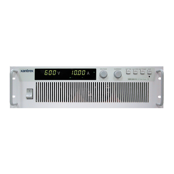
Front Panel Front Panel Figure 1.1 Front Panel 1. Rack mount brackets 2. Handles 3. On/Off switch 4. Air intake vents 5. Front panel display. See 6. Voltage knob: Turn knob to increase or decrease output voltage. 7. Current knob: Turn knob to increase or decrease output current limit. 8. -
Page 21: Status Annunciators
Status Annunciators Figure 1.2 Front Panel Display, Status Annunciators 1. AC: The AC input is out of range and has caused the output of the supply to be shut down (red) 2. OTP: The internal Over Temperature Protection threshold has been exceeded, disabling the supply output until the sensors cool to within the normal operating temperature range (red) 3. -
Page 22: Rear Panel Connectors And Switch
Rear Panel Connectors and Switch Rear Panel Connectors and Switch Figure 1.3 Rear panel 1. Fan Exhaust Vents: Do Not Obstruct. 2. Remote Sensing Ports: From the rear panel point of view, left is negative; right is positive. 3. DC Output: Bus bars are shown. Terminal blocks are used for higher voltages (150 Vdc and higher). - Page 23 1 Resistive Programming of Output Voltage 2 Resistive Programming of Output Current Limit 3 Selects Output Voltage Programming and Monitor Range select 4 Selects Output Current Limit Programming and Monitor Range select 5 Selects Output Voltage Control: Local or Remote 6 Selects Output Current Control: Local or Remote 7 Selects Remote Interlock Logic 8 Selects Over Temperature Shutdown Reset Mode...
-
Page 24: Rear Panel J1 Connector
Rear Panel Connectors and Switch Rear Panel J1 The J1 Programming and Monitoring connector is a 15-terminal wire clamp connector located on the power supply’s rear panel. See Connector provides access to the following functions: Remote programming of output voltage AND/OR current limit •... - Page 25 Table 1.2 Rear Panel J1 Connector Terminals and Functions Reference Name J1-1 VPGM Output Voltage Programming Input J1-2 IPGM Output Current Limit Programming Input J1-3 RTN-P Program Return J1-4 VMON Output Voltage Monitor J1-5 IMON Output Current Monitor J1-6 RTN-M Monitor Return J1-7 No connection...
- Page 26 About The XPR Power Supply Rear Panel Connectors and Switch Operating Manual for XPR Series Power Supply...
-
Page 27: Section 2. Installation
Section 2. Installation Overview Section 2 provides recommendations and procedures for inspecting, installing, and testing the power supply. For more information about controls and connectors, refer to the front panel diagram Section Basic Setup Procedure Table 2.1 provides a summary of the setup procedure and an overview of the subsections in this chapter. -
Page 28: Inspection, Cleaning, And Packaging
Inspection, Cleaning, and Packaging Inspection, Cleaning, and Packaging Initial When you receive your power supply, do a quick visual check. Inspection 1. Ensure that the box contains the power supply, the operating manual, the AC input cover and strain relief, and the output cover. 2. -
Page 29: Returning Power Supplies To The Manufacturer
This warranty will not apply where the product is damaged due to improper packaging. 2. Include the following: The RMA number supplied by Xantrex Technology Inc clearly marked on • the outside of the box. -
Page 30: Packaging For Shipping Or Storage
Returning Power Supplies to the Manufacturer Packaging for Follow these instructions to prepare the unit for shipping or storage. Shipping or 1. When returning the unit or sending it to the service center, attach a tag to the unit Storage stating its model number (available from the front panel label) and its serial number (available from the rear panel label). -
Page 31: Location, Mounting, And Ventilation
Location, Mounting, and Ventilation Use the power supply in rack-mounted applications only. The power supply is designed to fit in a standard 19 in. (483mm) equipment rack. Rack Mounting WARNING- High Energy and High Voltage Ensure that the 8-32 rack mounting screws do not extend more than 1/8 in. (3.0mm) into the sides of the power supply. - Page 32 Installation Location, Mounting, and Ventilation Figure 2.2 Unpacking the Power Supply Operating Manual for XPR Series Power Supply...
-
Page 33: Ventilation
Installation Location, Mounting, and Ventilation Figure 2.3 Mounting the Power Supply in the Rack With Support Rails Ventilation Allow cooling air to reach the ventilation inlets on the front of the unit and allow 4 in. (10 cm) of unrestricted air space at the rear of the unit for the fan exhaust. Ventilation inlets are located on the top and sides;... -
Page 34: Ac Input Power
AC Input Power AC Input Power WARNING Disconnect AC power from the unit before removing the connector cover. Live line voltages may be exposed when the cover is removed. WARNING A safety ground wire must be connected to the unit as shown in operator safety. -
Page 35: Ac Input Wire
AC Input Wire The manufacturer recommends the AC input wire specified in be permanently connected to an approved AC distribution box with suitably rated over-current protection. If you require a special cord, contact the manufacturer. Table 2.2 AC Wire Specification for 6000 Watt units AC Input Voltage Range 190–242Vac, 47–63Hz, 3-phase, 4 wire (standard) - Page 36 Installation AC Input Power It is now safe to turn the power supply on. Figure 2.5 Attaching the AC Input Wires Operating Manual for XPR Series Power Supply...
-
Page 37: Basic Tests
Basic Tests WARNING The factory setting for Power ON is 0V and 0A. These settings can be changed by end users. If you suspect that the power supply has been used by someone else since it was received from the factory, be prepared for the unit to power ON with a live DC output. -
Page 38: Power On Check
Basic Tests Power ON To complete the power on check: Check 1. Ensure that the AC power switch is OFF. 2. Connect the unit to an AC outlet. 3. Turn the front panel AC power switch to ON. After a short power-on delay, the front panel meters and the CV annunciator illuminate. -
Page 39: Voltage Mode Operation Check
Voltage Mode 1. Ensure the voltage and current controls on the front panel are turned fully Operation counter-clockwise. Check 2. Connect a DVM to the output terminals on the rear panel, observing correct polarity. 3. Turn the current control a 1/2-turn clockwise. Slowly turn the voltage control clockwise and observe both the front panel voltmeter and the DVM. -
Page 40: Front Panel Function Checks
Basic Tests Front Panel 1. Turn the front panel power switch to ON. Function 2. Set voltage and current controls fully clockwise. Push the OUT ON/OFF switch Checks to its IN position and check that the voltmeter reading falls to zero and the OFF (OUTPUT OFF) LED turns on. -
Page 41: Load Wiring
Load Wiring When connecting load wiring to the power supply, consider the following factors: Current carrying capacity of the wire • Maximum load wiring length for operation with sense lines • Noise and impedance effects of the load lines • Current As a minimum, load wiring must have a constant capacity greater than the output current rating of the power supply. -
Page 42: Load Wiring Length For Operation With Sense Lines
Load Wiring Load Wiring For applications using remote sensing, or for improved voltage regulation at the load, you must limit the voltage drop across each load line. We recommend that you use Length for larger load wiring to ensure a smaller voltage drop (1V maximum under full load Operation conditions), although units will compensate for up to 5V drop in each line with the with Sense... -
Page 43: Load Connections
Load Connections WARNING Exercise caution when operating the power supply. High energy levels can be stored at the output terminals on a power supply in normal operation. In addition, potentially lethal voltages exist in the power circuit and on the output and sense connectors of a power supply with a rated output greater than 40V. -
Page 44: Single Load
Load Connections Single Load To connect a single load to the DC output bus bars (5–80V outputs): 1. Ensure that the power supply is powered OFF. 2. Place a 5/16 in. (M8) bolt in the connecting hole of the negative bus bar, and fasten the negative wire or bus bar, a flatwasher, lockwasher, and a nut to the bolt. -
Page 45: Multiple Loads
Multiple To connect multiple loads in parallel: Loads Follow the • To minimize interaction between loads, bring the wiring for each load directly • back to the supply output. When each load to the power supply is wired separately, the loads will see only the precisely regulated output from the supply. If 2 loads share a single cable, the fluctuation in current to one load will cause the voltage to vary on the others. -
Page 46: Output Strain Relief/Cover
Load Connections Output Strain Figure 2.7 Relief/Cover from accidental contact with the bus bars and to clamp output cables in place. Figure 2.7 Output Bus Bar Cover Figure 2.8 Output Cover with Strain Relief for installation of the output cover. Use this cover to protect users (Low and Medium Voltage) (High Voltage 100–600V) Operating Manual for XPR Series Power Supply... -
Page 47: Remote Sensing
Remote Sensing The power supply regulates the output voltage at the output connectors in its normal configuration without remote sense lines connected. Remote sensing lets the power supply track and regulate the output voltage at the load, and thereby compensate for the voltage drop in the load lines. The power supply will only compensate within the limitations of its voltage rating, to a maximum of 5V per load line. - Page 48 Installation Remote Sensing Operating Manual for XPR Series Power Supply...
-
Page 49: Section 3. Operation
Section 3. Operation Overview Once you have installed the power supply and connected both the AC input power and the load as explained in configuration and is ready to operate in local control mode. Section 3 then provides information about configuring the power supply, and also gives procedures for operating the supply via the front panel controls. -
Page 50: Power Supply Operating States
Power Supply Operating States Power Supply Operating States The power supply has 4 operating states: Power-On • Output Shutdown • Soft Start • Normal Operation • Power-On This is the period between the time that AC power is applied to the supply (AC breaker turned on) and the time that the power supply is ready for operation. -
Page 51: Power Supply Regulation Modes
Power Supply Regulation Modes The power supply has 2 regulation modes while in the Normal Operation State: Constant Voltage (CV) • Constant Current (CC) • The CV and CC annunciators indicate the regulation mode. Constant In this mode, the supply’s output voltage is constant while the current and power vary with the load. -
Page 52: Front Panel Controls
Front Panel Controls Front Panel Controls The power supply is shipped ready to operate in local mode using the front panel knobs and function buttons. This section describes the function buttons and control knobs that you use to operate the power supply. (Additional details about the front panel keys, control knobs, and display annunciators are provided in The next section provides details about configuring and operating the power supply. -
Page 53: Using Over Voltage Protection (Ovp)
Using Over Voltage Protection (OVP) The OVP circuit protects the load in the event of a remote programming error, an incorrect voltage control adjustment, or a power supply failure. The protection circuit monitors the output voltage at the output of the power supply and will shut down the main power converter whenever a preset voltage limit is exceeded. -
Page 54: Resetting The Ovp Circuit
Using Over Voltage Protection (OVP) Resetting the To reset the OVP circuit after it activates: OVP Circuit 1. Reduce the power supply’s output voltage setting to below the OVP set point. 2. Press the OUT ON/OFF switch IN. The OFF LED on the front panel turns on. The OVP LED turns off. -
Page 55: Using The Shutdown Function (Output On/Off)
Using the Shutdown Function (Output ON/OFF) Use the shutdown function to disable or enable the supply’s output so that you can make adjustments to either the load or the power supply without shutting off the power supply. Activate this function from the front panel at any time by using the OUT ON/OFF switch. -
Page 56: Over Temperature Protection (Otp)
Over Temperature Protection (OTP) Note If switch S1-7 is ON but there is no signal applied, the INT LED turns on and the power supply will not provide an output until the HIGH signal level is applied. Any of the eight switches on S1 is OFF when it has been flipped up to break contact, ON when flipped down to close contact. -
Page 57: User Diagnostics
User Diagnostics If your power supply is not performing as described in this manual, run through the procedures and checks in this section before calling your service technician. These procedures are confined to operator level functions only and do not require cover-off servicing. - Page 58 User Diagnostics Table 3.3 User Diagnostics Symptom Check No output and the Is input voltage within specified display is blank. range? Power switch ON? Internal circuit? No output but the OVP LED turned on? display turns on. Front panel INT LED turned on? OTP LED turned on? Current limit set to zero? Voltage control set to zero?
-
Page 59: Alarms
Alarms WARNING- Fire Hazard If an over-voltage, over-current, or over-power protection error persists without apparent cause, press OUT ON/OFF button to disable the output, and turn the AC switch OFF. Inspect the load and power supply for evidence of an electrical fault. The power supply should not be brought back into operation if there is any evidence of an electrical fire or other safety hazards. - Page 60 Operation Alarms Operating Manual for XPR Series Power Supply...
-
Page 61: Section 4. Remote Operation
Section 4. Remote Operation Introduction The rear panel switches and connector on the power supply allow you to program the supply with an analog device or to output readback signals. This section covers the following topics: “Remote Analog Programming of Output Voltage and Current Limit” on •... -
Page 62: Making Connections For Remote Control
Making Connections for Remote Control Making Connections for Remote Control Figure 4.1 Figure 4.1 Location of J1 and S1 Remote The interlock input may be configured for use with an external voltage free contact. Connect pins as shown: Shutdown Using a Table 4.1 Analog Pin Connections with a Contact Closure Contact Programming Line Pin #... -
Page 63: Remote Analog Programming Of Output Voltage And Current Limit
Remote Analog Programming of Output Voltage and Current Limit Remote analog programming allows control of the power supply’s output voltage and/or current limit to shift from local operation at the front panel voltage and current controls to external analog sources. As you vary the external programming source, the power supply’s output varies proportionally over its output range. -
Page 64: Remote Analog Programming Procedure
Select Remote Control Function Resistive programming is selected at rear panel switch S1: S1-1 and S1-2 are ON. CAUTION Before turning on the power supply in resistive programming mode, make sure that the resistors are connected at J1-1 to J1-3 and J1-2 to J1-3. Remote Analog Programming... - Page 65 Table 4.3 Power Supply Settings for Different Programming Sources Power Supply Output Current Limit: Programming Source 0-5 Vdc S1-1= S1-2= S1-3= S1-4= S1-5=ON S1-6=ON S1-1= S1-2= S1-3=ON S1-4= S1-5=ON S1-6=ON S1-1=ON S1-2= S1-3= S1-4= S1-5=ON S1-6=ON S1-1=ON S1-2= S1-3=ON S1-4= S1-5=ON S1-6=ON S1-1=...
-
Page 66: Remote Monitoring Of Output Voltage And Current
Remote Monitoring of Output Voltage and Current Remote Monitoring of Output Voltage and Current Readback The J1 connector on the rear panel provides access to calibrated readback signals for remote monitoring of the output voltage and current. Rear panel switches S1-3 and Signals S1-4 allow you to select either a 0-5 Vdc or a 0-10 Vdc range for the output. -
Page 67: Appendix A. Specifications And Characteristics
Appendix A. Specifications and Characteristics Notes • These specifications are represented over the full operating temperature range. • Nominal line input voltage assumed unless otherwise stated. • All sense lines are configured for default local operation. • All specifications are subject to change without notice. Release 1.1... -
Page 68: Electrical Specifications-Summary
Electrical Specifications—Summary Electrical Specifications—Summary Table A.1Specifications for 6000 Watt units (10V to 60V Models) Models Output Ratings: Output Voltage Output Current Output Power Line Regulation: Voltage (0.01% of Vmax) Current (0.05% of Imax) Load Regulation: Voltage (0.05% of Vmax + 5 mV) Current (0.1% of Imax + 20 mA) Meter Accuracy: Voltage (0.5% of Vmax + 1 count) - Page 69 Table A.2Drift Specifications for 6000 Watt units (10V to 60V Models) Models Drift (30 minutes): Voltage (0.04% of Vmax) Current (0.6% of Imax) Drift (8 hours): Voltage (0.02% of Vmax) Current (0.04% of Imax) Temperature Coefficient: Voltage (0.04% of Vmax/°C) Current (0.06% of Imax/°C) 1.
- Page 70 Electrical Specifications—Summary Table A.3Specifications for 6000 Watt units (80V to 600V Models) Models Output Ratings: Output Voltage Output Current Output Power Line Regulation: Voltage (0.01% of Vmax) Current (0.05% of Imax) Load Regulation: Voltage (0.05% of Vmax + 5 mV) Current (0.1% of Imax + 20 mA) Meter Accuracy: Voltage (0.5% of Vmax + 1 count)
- Page 71 Table A.4Drift Specifications for 6000 Watt units (80V to 600V Models) Models Drift (30 minutes): Voltage (0.04% of Vmax) Current (0.6% of Imax) Drift (8 hours): Voltage (0.02% of Vmax) Current (0.04% of Imax) Temperature Coefficient: Voltage (0.04% of Vmax/°C) Current (0.06% of Imax/°C) 1.
-
Page 72: Ac Line Input Specifications
AC Line Input Specifications AC Line Input Specifications The input to the power supply requires the following specifications. AC Line Input Voltage Operating Ranges Table A.5AC Line Input Specifications Operating Range nominal 208V nominal 400V Frequency Range Maximum Peak In-rush Current at turn on 35 A Minimum Power Factor nominal 208V nominal 400V... -
Page 73: Output Performance Specifications
Output Performance Specifications These specifications define the electrical performance specifications of the power supply output. These specifications apply to both local and remote sense configurations, except where noted. These specifications apply to all programming sources, except where noted. Rated Output Range Voltage Current Efficiency... - Page 74 Output Performance Specifications Programming Accuracy Remote Analog Programming Interface Voltage Programming Resistive Programming Readback Accuracy Front Panel or Remote Analog Programming Interface Voltage Readback Current Readback 30 Minute Drift Voltage Current 8 Hour Drift Temperature Stability Voltage Current Temperature Coefficients Front Panel or Analog Programming Interface Voltage Programming Current Programming...
- Page 75 Analog Programming Interface Programming Lines, Impedance 0-5 V range 0-10 V range Readback Lines, Impedance 0-5 V range 0-10 V range Isolation, all program and readback lines Interlock - Remote Shutdown 4-15 V signal or TTL-compatible output, selectable logic TTL input impedance Maximum Supply Voltage Minimum Supply Voltage User Supply Voltage...
- Page 76 Output Performance Specifications Fall Time For a programmed 95% to 5% step in output voltage. Load Condition No Load Full Load Time Delay From Power On Until Output Stable 5 s maximum (Within regulation envelope) Time Delay From Output Enable Until Output Stable 2 s maximum (Within regulation envelope) Output Hold-Up Time –...
-
Page 77: Environmental Specification
Maximum Remote Sense Line Drop Compensation Minimum 3.8 V for each line, 5 V typical Isolation AC Input to Output AC Input to Chassis Output to Chassis Environmental Specification Thermal Specification Operating Temperature Range Storage Temperature Range Consult the factory for operation below 0°C and above 50°C. -
Page 78: Mechanical Specification
Mechanical Specification Mechanical Specification Weight 6000 W: approx. 75 lb. (34 kg) for 10 V-600 A unit, without packaging Size 5.2 in. 133 mm Figure A.1 Power Supply Dimensions 18.2 in. 462 mm 19 in. 483 mm Operating Manual for XPR Series Power Supply 21 in. - Page 80 Xantrex Technology Inc. 8999 Nelson Way Burnaby, British Columbia Canada V5A 4B5 604 422 8595 Tel 604 421 3056 Fax 800 667 8422 Toll Free North America prg.info@xantrex.com www.xantrex.com TM-P6OP-01XN PRINTED IN CANADA...