
Related Manuals for Xantrex XPF 60-20


Summary of Contents for Xantrex XPF 60-20
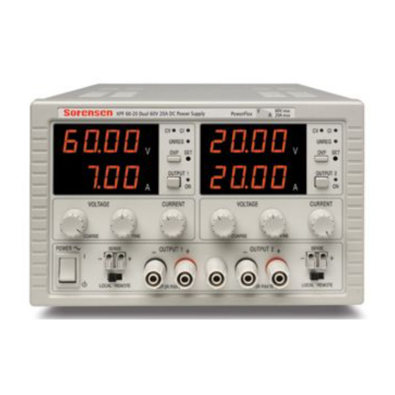
- Page 1 XPF Series Dual Output 60V 20A Powerflex DC Power Supply XPF 60-20 Operating Manual...
-
Page 2: Contact Information
About Xantrex Xantrex Technology Inc. is a world-leading supplier of advanced power electronics and controls with products from 50 watt mobile units to one MW utility-scale systems for wind, solar, batteries, fuel cells, microturbines, and backup power applications in both grid-connected and stand-alone systems. -
Page 3: Table Of Contents
Specification Safety Installation Connections Operation Maintenance Calibration Instructions en Francais Sécurité Installation Connexions Opération Maintenance Bedienungsanleitung auf Deutsch Sicherheit Installation Anschlüsse Betrieb Wartung Istruzioni in Italiano Sicurezza Installazione Collegamento Funzionamento Manutenzione Instrucciones en Español Seguridad Instalación Conexiones Funcionamiento Mantenimiento Warranty Information Table of Contents... -
Page 4: Specification
Change in output for any load change within PowerFlex envelope, remote sense connected: Constant voltage: <0.01% of maximum output Constant current: <0.05% of maximum output 4mVrms max; typically <2mVrms, <10mV pk-pk, at maximum load, CV mode. Specification XPF 60-20 POWER ENVELOPE... - Page 5 Transient Load Response: Temperature Coefficient: Status Indication: METER SPECIFICATIONS Meter Types: Meter Resolutions: Meter Accuracies: GENERAL AC Input: Power Consumption: Operating Range: Storage Range: Environmental: Safety: EMC: Size: Weight: <250us to within 50mV of set level for a 5% to 95% load change. Typically <100ppm/°C Output on lamp.
-
Page 6: Safety
This power supply is a Safety Class I instrument according to IEC classification and has been designed to meet the requirements of EN61010-1 (Safety Requirements for Electrical Equipment for Measurement, Control and Laboratory Use). It is an Installation Category II instrument intended for operation from a normal single phase supply. -
Page 7: Emc
This instrument has been designed to meet the requirements of the EMC Directive 89/336/EEC. Compliance was demonstrated by meeting the test limits of the following standards: Emissions EN61326 (1998) EMC product standard for Electrical Equipment for Measurement, Control and Laboratory Use. Test limits used were: a) Radiated: Class B b) Conducted:... -
Page 8: Installation
Mains Operating Voltage This instrument has a universal input range and will operate from a nominal 115V or 230V mains supply without adjustment. Check that the local supply meets the AC Input requirement given in the Specification. Mains Lead Connect the instrument to the AC supply using the mains lead provided. Should a mains plug be required for a different mains outlet socket, a suitably rated and approved mains lead set should be used which is fitted with the required wall plug and an IEC60320 C13 connector for the instrument end. -
Page 9: Operation
Power Limit The maximum output at different voltage settings is limited by the power envelope illustrated below: Operation XPF 60-20 POWER ENVELOPE... -
Page 10: Connection To The Load
The power envelope is set to give 62V/7A, 42V/10A and 20V / 20A under all supply conditions (both outputs loaded); at lower output voltages the output power is restricted by the 20A current maximum. When the power limit is exceeded, the status indication will change from CV or CI to UNREG. For example, if the supply is set to 20V, with the current limit at maximum, and is connected to a 2Ω... -
Page 11: Maintenance
When the output is tripped the OUTPUT lamp will still be ON but the displays will show ‘OP trip’ and the UNREG lamp will also light. Turn the output off; the trip message should be replaced with the normal preset V and I readings. When the cause of the trip has been removed the output can be switched on again. -
Page 12: Calibration
Allow at least 5 minutes warm-up before commencing calibration. Access to Calibration Adjustments All routine calibration adjustments are on the front panel control board which is mounted directly behind the board carrying the front panel controls. Component adjustment references are given as Output 1/Output 2, e.g. -
Page 13: Voltage Calibration
Voltage Calibration Set the sense switch to local. Switch output ON and set output volts to exactly 0.02V on the display. Switch output OFF and adjust VR16/116 (preset Volts offset compensation) for exactly 0.02V on the display. Connect the DMM (set to Volts) across the output. Switch output ON (check LED is on) and check the Amps display reads 0.00 ±... -
Page 14: Sécurité
Cet instrument est de Classe de sécurité 1 suivant la classification IEC et il a été construit pour satisfaire aux impératifs EN61010-1 (impératifs de sécurité pour le matériel électrique en vue de mesure, commande et utilisation en laboratoire). Il s'agit d'un instrument d'installation Catégorie II devant être exploité... -
Page 15: Installation
Tension d’utilisation secteur Cet instrument a une plage d'entrée universelle et il fonctionne sur une alimentation secteur de 115 V ou de 230 V, tension nominale, sans ajustement aucun. Vérifier que l'alimentation locale satisfait aux impératifs d'entrée c.a. indiqués aux Caractéristiques techniques. Câble secteur Branchez cet instrument sur l’alimentation secteur en utilisant le câble d’alimentation fourni. -
Page 16: Opération
Limite de puissance La sortie maximale à différents réglages de tension est limitée par l’enveloppe de puissance illustrée ci-dessous: Opération XPF 60-20 ENVELOPPE DE PUISSANCE... - Page 17 L’enveloppe de puissance est réglée pour donner 62 V/7 A, 42 V/10 A et 20 V/20 A à toutes les conditions d’alimentation (les deux sorties chargées); à de plus basses tensions de sortie, la puissance de sortie est restreinte par le courant de 20 A maximum. Si la limite de puissance est dépassée, l’indication de l’état passe de CV ou de CI à...
-
Page 18: Maintenance
potentiomètre pour augmenter la limite, puis appuyer sur le bouton sous le potentiomètre pour lire les valeurs directement sur l’affichage de l’utilisateur. Si, pour une raison quelconque, la tension de sortie dépasse la tension de protection OVP préréglée, y compris la tension forcée de manière externe, il se produira un déclenchement de la sortie. -
Page 19: Sicherheit
Dieses Gerät wurde nach der Sicherheitsklasse (Schutzart) I der IEC-Klassifikation und gemäß den europäischen Vorschriften EN61010-1 (Sicherheitsvorschriften für elektrische Mess-, Steuer, Regel- und Laboranlagen) entwickelt. Es handelt sich um ein Gerät der Installationskategorie II, das für den Betrieb mit einer normalen einphasigen Versorgung vorgesehen ist. Das Gerät wurde gemäß... -
Page 20: Installation
Netzbetriebsspannung Das Gerät besitzt einen universellen Eingangsbereich und kann ohne jede weitere Einstellung mit einer Nenn-Netzversorgung von 115 oder 230 V betrieben werden. Stellen Sie sicher, daß die Versorgung am Ort den in der Spezifikation aufgeführten Eingangsanforderungen entspricht. Netzkabel Schließen Sie das Instrument unter Verwendung des mitgelieferten Netzkabels an die Wechselstromversorgung an. -
Page 21: Betrieb
Bei Kurzschließung des Ausgangs wird ein kurzer Stromimpuls erzeugt, wenn sich der Kondensator entlädt, welcher unabhängig vom eingestellten Stromgrenzwert ist. Leistungsgrenze Der maximale Ausgang bei unterschiedlichen Spannungseinstellungen wird durch die unten ab gebildete Leistungshüllkurve (power envelope) begrenzt: ) und Eingeschaltet ( l ). Im Bereitschaftszustand bleibt der Betrieb XPF 60-20 LEISTUNGS-HÜLLKURVE... - Page 22 Die Leistungshüllkurve ist so eingestellt, dass unter Versorgungsbedingungen (wenn beide Ausgänge belastet sind) 62V/7A, 42V/10A und 20V/20A abgegeben werden. Bei niedrigeren Ausgangsspannungen wird die Ausgangsleistung durch den maximalen Strom von 20A begrenzt. Beim Überschreiten der Leistungsgrenze verändert sich die Statusanzeige von DV oder CI auf UNREG.
- Page 23 Zu beachten ist, dass die Ausgangsklemmen für maximal 30 A vorgesehen sind. Werden zwei oder mehr Ausgänge parallel betrieben, um höhere Ströme als diesen zu liefern, so sollte die Verbindung an einer getrennten Stelle vorgenommen werden, nicht an einer der Klemmen. Überspannungsschutz Der Überspannungsschutz lässt sich im Bereich 10 % bis 110 % der maximalen Ausgangsstufe der Stromversorgung variieren.
-
Page 24: Wartung
Die Hersteller bzw. deren Vertretungen im Ausland bieten die Reparatur von Geräten an, bei denen eine Störung aufgetreten ist. Wenn der Eigentümer die Wartungsarbeiten selbst durchführen möchte, hat er dafür Sorge zu tragen, dass diese Arbeiten ausschließlich von entsprechend qualifiziertem Personal und gemäß Wartungshandbuch ausgeführt werden, das direkt von den Herstellern oder deren Vertretungen im Ausland bezogen werden kann. -
Page 25: Sicurezza
Questo strumento appartiene alla Categoria di Sicurezza 1 secondo la classifica IEC ed è stato progettato in modo da soddisfare i criteri EN61010-1 (requisiti di Sicurezza per Apparecchiature di misura, controllo e per uso in laboratorio). E’ uno strumento di Categoria II di installazione e inteso per funzionamento con un’alimentazione normale monofase. -
Page 26: Installazione
Tensione d’esercizio Questo strumento è dotato di un’entrata universale e funziona con un’alimentazione a 115V o 230V senza regolazione. Controllare che la rete locale soddisfi i requisiti d’entrata indicati nella specifica. Cavo d’Alimentazione Collegare lo strumento all’alimentazione di rete in corrente alternata utilizzando il cavo fornito. Se dovesse essere necessaria una spina di alimentazione diversa, utilizzare un set completo della spina necessaria e di un connettore tipo IEC60320 C13 adeguatamente dimensionati e omologati. -
Page 27: Funzionamento
L’inviluppo di potenza è impostato per dare 62V/7A, 42V/10A e 20V/20A sotto tutte le condizioni di carico (ambedue le uscite sotto carico); a tensioni in uscita più basse la potenza in uscita viene ristretta dal limite massimo di corrente di 20A. Funzionamento XPF 60-20 INVILUPPO DIPOTENZA... - Page 28 Quando si eccede il limite di potenza, l’indicazione di stato cambia da CV (tensione costante) o CI (corrente costante) in UNREG (non regolata). Ad es., se l’alimentazione è impostata a 20 V con il limite di corrente al massimo ed è collegata a un carico di 2Ω, la corrente sarà di 10 A e l’alimentazione rimane in modalità...
-
Page 29: Manutenzione
Se per qualsiasi ragione la tensione sull’uscita eccede il limite di protezione di sovratensione impostato, anche a causa di una tensione esterna forzata, scatta l’interruzione dell’uscita. L’uscita viene interrotta anche se si tenta di prelevare potenza dai cavi di rilevamento. Dopo lo scatto d’interruzione dell’uscita, la lampada OUTPUT rimane accesa ma la visualizzazione mostra ‘OP trip’... -
Page 30: Seguridad
Este es un instrumento de Clase de Seguridad I según la clasificación del IEC y ha sido diseñado para cumplir con los requisitos del EN61010-1 (Requisitos de Seguridad para Equipos Eléctricos para la Medición, Control y Uso en Laboratorio). Es un instrumento de Categoría de Instalación II propuesto para ser usado con un suministro monofásico normal. -
Page 31: Instalación
Voltaje de trabajo de alimentación Este instrumento tiene un rango de entrada universal y funcionará sin necesidad de ajustes en suministros eléctricos de 115V o 230V. Compruebe que el suministro local satisface los requisitos de entrada CA que se estipulan en Especificaciones. Cable de red Conectar el instrumento al suministro de CA usando el cable de la red incluido. -
Page 32: Funcionamiento
Límite de potencia La salida máxima a distintos ajustes de voltaje está limitada por la envoltura de potencia que se ilustra debajo: Funcionamiento XPF 60-20 ENVOLTURA DE POTENCIA... - Page 33 La envoltura de potencia está fijada para producir 62V/7A, 42V/10A y 20V/20A bajo toda condición de suministro (con ambas salidas cargadas); para salidas de voltaje inferiores, la potencia de salida está limitada por la corriente máxima de 20A. Al superar el límite de potencia, el indicador de estado cambiará de CV o CI a UNREG. Por ejemplo, si la fuerza está...
-
Page 34: Mantenimiento
leerse directamente en el visualizador presionando el botón debajo del prefijado. Si el voltaje de la salida supera al OVP fijado por cualquier motivo, incluyendo un voltaje forzado externamente, la salida se "disparará", cortándose. La salida también se disparará si se tratara de extraer fuerza de los cables detectores. -
Page 35: Warranty Information
Warranty What does this warranty cover? This Limited Warranty is provided by Xantrex Technology, Inc. ("Xantrex") and covers defects in workmanship and materials in your XPF series. This warranty lasts for a Warranty Period of three years (3 years) from the date of purchase at point of sale to you, the original end user customer. - Page 36 What does this warranty not cover? This Limited Warranty does not cover normal wear and tear of the product or costs related to the removal, installation, or troubleshooting of the customer's electrical systems. This warranty does not apply to and Xantrex will not be responsible for any defect in or damage to: a) the product if it has been misused, neglected, improperly installed, physically damaged or altered, either internally or externally, or damaged from improper use or use in an unsuitable environment;...
- Page 37 Xantrex Technology Inc. 9250 Brown Deer Road San Diego, CA USA, 92121 858-450-0085 Tel 858-678-4482 Fax 800 733-5427 Toll Free North America prg.info@xantrex.com www.xantrex.com M370043-01 Rev A 48511-1080 Issue 1...