Table of Contents
Advertisement
Advertisement
Table of Contents

Related Manuals for Xantrex 42V 10A


Summary of Contents for Xantrex 42V 10A
-
Page 1: Power Supply
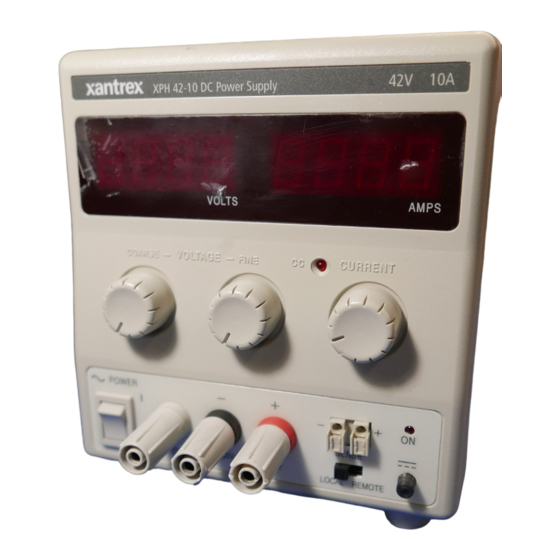
XPH Series 42V 10A DC Power Supply XPH 42-10 Operating Manual... -
Page 2: Contact Information
About Xantrex Xantrex Technology Inc. is a world-leading supplier of advanced power electronics and controls with products from 50 watt mobile units to one MW utility-scale systems for wind, solar, batteries, fuel cells, microturbines, and backup power applications in both grid-connected and stand-alone systems. -
Page 3: Table Of Contents
The XPH 42-10 is an exceptionally compact and lightweight single output laboratory dc power supply providing 0 to 42V at 0 to 10A. The XPH 42-10 uses mixed−mode regulation technology which combines switch−mode pre−regulation with linear post−regulation. Special techniques are used to maintain very high efficiency whilst achieving noise levels that are close to that of a pure linear regulator. -
Page 4: Specification
OUTPUT Voltage Range: Current Range: Output Voltage Setting: Output Current Setting: Operating Mode: Output Switch: Output Terminals: Output Impedance: Output Protection: Over-temperature Protection: Load & Line Regulation: Ripple & Noise (20MHz bandwidth): Transient Response: Temperature Coefficient: Status Indication: METER SPECIFICATIONS Meter Types: Meter Resolutions: Meter Accuracies:... -
Page 5: Safety
This power supply is a Safety Class I instrument according to IEC classification and has been designed to meet the requirements of EN61010-1 (Safety Requirements for Electrical Equipment for Measurement, Control and Laboratory Use). It is an Installation Category II instrument intended for operation from a normal single phase supply. -
Page 6: Emc
This instrument has been designed to meet the requirements of the EMC Directive 89/336/EEC. Compliance was demonstrated by meeting the test limits of the following standards: Emissions EN61326 (1998) EMC product standard for Electrical Equipment for Measurement, Control and Laboratory Use. Test limits used were: Radiated: Class B Conducted: Class B... -
Page 7: Installation
Mains Operating Voltage Check that the instrument operating voltage marked on the rear panel is suitable for the local supply. Mains Lead When a three core mains lead with bare ends is provided this should be connected as follows: BROWN BLUE GREEN/YELLOW When fitting a fused plug a 5 amp fuse should be fitted inside the plug. -
Page 8: Operation
Setting Up the Output With the POWER switch on ( accurately preset using the VOLTAGE and CURRENT controls; the left-hand meter shows the set voltage and the right-hand meter shows the set maximum current. When the output switch is switched on, the ON lamp lights; the left-hand meter now shows the actual voltage and the right-hand meter the actual load current. -
Page 9: Maintenance
Series or Parallel Connection with Other Outputs The outputs of the power supply are fully floating and may be used in series with other power supply units to generate high DC voltages up to 300V DC. The maximum permissible voltage between any terminal and earth ground ( WARNING! Such voltages are exceedingly hazardous and great care should be taken to shield the output terminals for such use. -
Page 10: Instructions En Francais
Ce système alimentation est un instrument de classe de sécurité 1 conforme à la classification IEC et il a été conçu pour satisfaire aux exigences de la norme EN61010-1 (Exigences de sécurité pour les équipements électriques de mesure, de contrôle et d'utilisation en laboratoire). Il s'agit d'un instrument de Catégorie II d'installation devant être exploité... - Page 11 Tension d’utilisation secteur Vérifier que la tension opérationnelle de l'instrument indiquée sur le panneau arrière est appropriée pour l'alimentation locale. Câble secteur Relier de la manière suivante tout câble secteur à trois conducteurs à fils nus: MARRON BLEU VERT/JAUNE Lors du montage d'une fiche à fusible, mettre un fusible de 5 A à l'intérieur de la fiche. Il est possible que les couleurs des fils du câble secteur de cet appareil ne correspondent pas aux marques de couleur d'identification des bornes de la fiche, et par suite, il est recommandé...
- Page 12 Réglage de la sortie L’interrupteur POWER (alimentation) sur ( précision la limite de tension et de courant de sortie au moyen des commandes VOLTAGE (Tension) et CURRENT (Courant); l’appareil de mesure gauche indique la tension réglée et l’appareil droit le courant maximum réglé. Lorsque le commutateur de sortie l’appareil de mesure gauche indique alors la tension véritable et l’appareil droit le courant de charge véritable.
- Page 13 Connexion en série ou en parallèle avec d’autres sorties Les sorties de l’alimentation sont entièrement flottantes et elles peuvent être utilisées en série avec d’autres blocs d’alimentation, afin de produire des tensions c.c. jusqu’à 300 V c.c. La tension maximale admissible entre une borne et la terre ( AVERTISSEMENT! Des tensions de ce genre sont extrêmement dangereuses et il faut prendre toutes les précautions d’usage pour protéger les bornes de sortie en conséquence.
-
Page 14: Bedienungsanleitung Auf Deutsch
Diese Stromversorgung wurde nach der Sicherheitsklasse (Schutzart) I der IEC-Klassifikation und gemäß den europäischen Vorschriften EN61010-1 (Sicherheitsvorschriften für Elektrische Meß-, Steuer, Regel- und Laboranlagen) entwickelt. Es handelt sich um ein Gerät der Installationskategorie II, das für den Betrieb von einer normalen einphasigen Versorgung vorgesehen ist. - Page 15 Netzbetriebsspannung Sicherstellen, daß die auf der Geräterückwand angegebene Betriebsspannung mit der Versorgungsspannung am Ort übereinstimmt. Netzkabel Steht nur ein Netzkabel ohne Stecker zur Verfügung, so ist es wie folgt anzuschließen: BRAUN BLAU GRÜN/GELB Bei Steckern mit eingebauten Sicherungen sollte eine 5 Ampere-Sicherung verwendet werden. Da die Farben der Netzkabeladern nicht unbedingt mit den Farbmarkierungen der Klemmen Ihres Steckers übereinstimmen, ist wie folgt vorzugehen: Die grün/gelbfarbene Ader ist an die mit E oder mit dem oben abgebildeten Schutzleitersymbol...
- Page 16 Einstellung des Ausgangs Bei eingeschaltetem POWER-Schalter (Netz I) und ausgeschaltetem Ausgang Ausgangsspannung und Strombegrenzung mit Hilfe der Knöpfe VOLTAGE (Spannung) und CURRENT (Strom) genau voreinstellen. Die linke Anzeige zeigt die eingestellte Spannung und die rechte den eingestellten Maximalstrom an. Wenn der Ausgangsschalter wird auf der linken Anzeige die Istspannung und an der rechten Anzeige der Ist-Laststrom angezeigt.
- Page 17 Abtastleitung gegeben ist. Dies lässt sich auf zweierlei Arten erreichen: entweder indem die Leitungen miteinander verdrillt werden oder indem ein koaxial geschirmtes Kabel (Abtastung über den Innerleiter) verwendet wird. Auch ein Elektrolytkondensator direkt am Lastanschlusspunkt kann hier von Nutzen sein. Der Spannungsabfall darf bei keiner Ausgangsleitung mehr als 0.5 Volt betragen.
- Page 18 Die Hersteller bzw. deren Vertretungen im Ausland bieten die Reparatur von Geräten an, bei denen eine Störung aufgetreten ist. Wenn der Eigentümer die Wartungsarbeiten selbst durchführen möchte, hat er dafür Sorge zu tragen, daß diese Arbeiten ausschließlich von entsprechend qualifiziertem Personal und gemäß Wartungshandbuch ausgeführt werden, das direkt von den Herstellern oder deren Vertretungen im Ausland bezogen werden kann.
-
Page 19: Istruzioni In Italiano
Questo alimentatore appartiene alla Categoria di Sicurezza 1 secondo la classifica IEC ed è stato progettato in modo da soddisfare i criteri EN61010-1 (requisiti di Sicurezza per Apparecchiature di misura, controllo e per uso in laboratorio). È uno strumento di Categoria II di installazione e inteso per funzionamento con un’alimentazione normale monofase. - Page 20 Tensione d’esercizio Controllare che la tensione d’esercizio dello strumento segnata sul pannello posteriore sia uguale a quella della rete elettrica locale. Cavo d’alimentazione Quando viene fornito un cavo a tre fili con le estremità nude, collegare come segue: MARRONE VERDE/GIALLO Quando si collega una spina dotata di portafusibile, in essa bisogna inserire un fusibile da 5A.
- Page 21 Corrente costante Se la resistenza al carico è sufficientemente bassa da far sì che, con la tensione di uscita impostata, scorra una corrente superiore al limite impostato, l’alimentazione assumerà automaticamente un funzionamento a corrente costante. L’uscita di corrente viene regolata con il comando CURRENT, mentre i comandi VOLTAGE impostano la tensione massima che è...
- Page 22 corrente impostato; a questo punto la tensione in uscita impostata scende al valore dell’impostazione più alta immediatamente inferiore e così via. In modalità di corrente costante, vari gruppi possono essere collegati in parallelo per erogare una corrente uguale alla somma dei limiti di corrente impostati.
-
Page 23: Instrucciones En Español
Esta fuente de alimentación es un dispositivo de Clase de Seguridad I según la clasificación del IEC y ha sido diseñado para cumplir con los requisitos de la norma EN61010-1 (Requisitos de Seguridad para Equipos Eléctricos para la Medición, Control y Uso en Laboratorio). Es un instrumento de Categoría de Instalación II propuesto para ser usado con un suministro monofásico normal. - Page 24 Tensión de la Red Eléctrica Verificar que la tensión de funcionamiento del instrumento que figura en el panel trasero concuerde con el suministro local. Cable de Red Cuando se suministra un cable de tres conductores con puntas peladas, se deberá conectar como sigue: MARRON AZUL...
- Page 25 Corriente Constante Si la resitencia de carga es suficientemente baja tal que, con la tensión de salida ajustada, correrá una corriente mayor que el límite de corriente ajustado, y la a,imentación eléctrica cambiará automáticamente a operación con corriente constante. Se ajusta la salida de corriente con el control ‘CURRENT’...
- Page 26 sucesivamente. En la modalidad de corriente constante, las unidades pueden conectarse en paralelo para proporcionar una corriente igual a la suma de los límites de corriente fijados. Se debe observar que la salida de los bornes está clasificada a un máximo de 15A; si varias salidas funcionan en paralelo para suministrar corrientes superiores a ésta, la junta debe efectuarse en un punto distinto y no en los bornes.
-
Page 27: Warranty Information
Warranty What does this warranty cover? This Limited Warranty is provided by Xantrex Technology, Inc. ("Xantrex") and covers defects in workmanship and materials in your XPH series. This warranty lasts for a Warranty Period of three years (3 years) from the date of purchase at point of sale to you, the original end user customer. - Page 28 What does this warranty not cover? This Limited Warranty does not cover normal wear and tear of the product or costs related to the removal, installation, or troubleshooting of the customer's electrical systems. This warranty does not apply to and Xantrex will not be responsible for any defect in or damage to: a) the product if it has been misused, neglected, improperly installed, physically damaged or altered, either internally or externally, or damaged from improper use or use in an unsuitable environment;...
-
Page 29: Return Material Authorization Policy
2. Include the following: • The RMA number supplied by Xantrex Technology, Inc. clearly marked on the outside of the box. • A return address where the unit can be shipped. Post office boxes are not acceptable. - Page 30 Xantrex Technology Inc. 8999 Nelson Way Burnaby, British Columbia Canada V5A 4B5 604 422 8595 Tel 604 421 3056 Fax 800 667 8422 Toll Free North America prg.info@xantrex.com www.xantrex.com 975-0105-01-01 48511-0750...