
Related Manuals for Xantrex XPD 120-4.5


Summary of Contents for Xantrex XPD 120-4.5
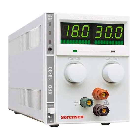
- Page 1 XPD 500 Watt Series Programmable DC Power Supply XPD 7.5-67 XPD 18-30 XPD 33-16 XPD 60-9 XPD 120-4.5 Operating Manual...
- Page 3 Operating Manual for XPD Series Programmable DC Power Supply...
- Page 4 What does this warranty cover and how long does it last? Warranty This Limited Warranty is provided by Xantrex Technology, Inc. (“Xantrex”) and covers defects in workmanship and materials in your XPD 500 Watt Series DC Power Supply. This warranty lasts for a Warranty Period of 5 years from the date of purchase at point of sale to you, the original end user customer.
- Page 5 Direct returns may be performed according to the Xantrex Return Material Authorization Policy described in your product manual. For some products, Xantrex maintains a network of regional Authorized Service Centers. Call Xantrex or check our website to see if your product can be repaired at one of these facilities. In any warranty claim, dated proof of purchase must accompany the product and the product must not have been disassembled or modified without prior written authorization by Xantrex.
- Page 6 Disclaimer Product THIS LIMITED WARRANTY IS THE SOLE AND EXCLUSIVE WARRANTY PROVIDED BY XANTREX IN CONNECTION WITH YOUR XANTREX PRODUCT AND IS, WHERE PERMITTED BY LAW, IN LIEU OF ALL OTHER WARRANTIES, CONDITIONS, GUARANTEES, REPRESENTATIONS, OBLIGATIONS AND LIABILITIES, EXPRESS OR IMPLIED, STATUTORY OR OTHERWISE IN CONNECTION WITH THE PRODUCT, HOWEVER ARISING (WHETHER BY CONTRACT, TORT, NEGLIGENCE, PRINCIPLES OF MANUFACTURER’S LIABILITY, OPERATION OF LAW, CONDUCT, STATEMENT OR OTHERWISE), INCLUDING WITHOUT RESTRICTION ANY IMPLIED WARRANTY...
- Page 7 Please record the following information when you first open your Power Supply package: About Your Power Model Number Supply Serial Number Purchased From Purchase Date Release Release A (2003-06) © Copyright Printed in Canada Release A ______________________________________________ ______________________________________________ ______________________________________________ ______________________________________________ 2002 Xantrex Technology Inc. All rights reserved.
- Page 8 Warnings Warnings and cautions are defined and formatted in this manual as shown below. Cautions WARNING Describes a potential hazard which could result in injury or death, or, a procedure which, if not performed correctly, could result in injury or death. CAUTION Describes a procedure which, if not performed correctly, could result in damage to data, equipment, or systems.
-
Page 9: About This Manual
About This Manual This Operating Manual contains operating information for the high-performance, switching, laboratory power supplies, available in several voltage models at 500 watts. It provides information on features and specifications, installation procedures, and basic functions testing, as well as operating procedures for using both front panel control and remote analog programming functions. - Page 10 Power Supply Safety Markings Alternating Current Earth (Ground) Terminal Protective Conductor Terminal viii Off (Supply) On (Supply) Caution (Check manual for additional information.) Operating Manual for XPD Series Power Supply...
-
Page 11: Table Of Contents
Contents About This Manual ........... vii Section 1. - Page 12 Section 3. Introduction ............35 Local Standard Operation .
-
Page 13: Description
Section 1. Features and Specifications Description current for a broad range of development and system requirements. The units use high-frequency soft-switching technology to achieve high power density and retain a small package size. They feature a built-in analog programming interface, with optional RS-232 and IEEE-488 controlled programming, making this series the first choice in flexible power system design. -
Page 14: Front Panel Controls
Front Panel Controls This unit may be equipped with an optional internal GPIB or RS-232 control for • remote digital programming and readback. Remote output sensing provides load cable compensation up to 5 V/line • (3 V/line for 7.5 V model). A rack mount kit (Option RM) is also available for this product. -
Page 15: Rear Panel Connectors
Rear Panel Connectors Remote Sensing Port: Remove Default Jumpers to use Remote Sensing Programming and Readback Output Busbars Figure 1.2 500 Watt Power Supply Rear Panel (7.5 V and 18 V) Remote Sensing Port: Remove Default Jumpers to use Remote Sensing 33 V, 60 V and 120 V models Figure 1.3 500 Watt Power Supply Rear Panel (33 V to 120 V) -
Page 16: Output Connectors
Rear Panel Connectors Output Low Voltage Models Equipped with positive and negative busbars. The busbars are offset to facilitate load cable connections. Connectors WARNING Disconnect the AC input before making any connections to the unit. Figure 1.4 Output Busbars - note polarity markings High Voltage Models High voltage models are equipped with a 4-terminal output block. -
Page 17: Rear Panel J210 Connector
Rear Panel The J210 Analog Interface connector is a 15-pin female DSUB connector located on the rear panel. See J210 shutdown 15 pin DSUB connector for remote programming and monitoring Connector functions. See recommend that you mate the J210 connector with a 15-pin male connector, such as a Tyco 747908-2 or equivalent. - Page 18 Rear Panel Connectors Table 1.2 Rear Panel J210 Connector Pins and Functions J210-1 J210-2 J210-3 J210-4 J210-5 J210-6 J210-7 J210-8 J210-9 J210-10 N/C J210-11 N/C J210-12 IMON J210-13 PGM/MON J210-14 VPGM J210-15 VMON 1. The TTL shutdown circuit is isolated to 500 V from the power supply output and chassis. 2.
-
Page 19: Making J210 Connections
Making J210 Connections CAUTION Program/monitor signal and return are internally connected to the power supply negative output. Do not attempt to bias these away from that potential. CAUTION To maintain the isolation of the power supply output and prevent ground loops, use an isolated (ungrounded) programming source when operating the power supply via remote analog control at the J210 connector. -
Page 20: Electrical Specifications
Electrical Specifications Electrical Specifications These specifications are warranted over a temperature range of 0 °C to 50 °C with local sense. Above 50 °C, derate output linearly to zero at 70 °C. Nominal line voltages are 100/120/200/230/240 Vac. Specifications and characteristics refer to a single output model unless otherwise stated, and specifications apply to either front or rear outputs unless noted. -
Page 21: Additional Specifications
1. Front output current limited to 30 A maximum. 2. For input voltage variation over the AC input voltage range, with constant rated load. 3. For 0 to 100% load variation, with constant nominal line voltage (rear output only). 4. Current mode noise is measured from 10% to 100% of rated output voltage, full current, resistive load. 5. -
Page 22: Additional Characteristics
Additional Characteristics Additional Characteristics Over Temperature Protection (OTP) OVP Control Switching Frequency Output Hold-up Time Insulation Resistance Isolation Voltage Remote Programming and Monitoring Remote S/D and Interlock Remote Analog Programming (Full Scale Input) Remote Monitoring Remote Programming and Monitoring Accuracy Maximum Remote Sense Line Drop Compensation Optional Digital Control... -
Page 23: Environmental Specifications
Environmental Specifications Operating Temperature Range Storage Temperature Range Humidity Range Operating Altitude Storage Altitude Installation Category Pollution Degree Mechanical Specifications Front Panel Voltage and Current Control Front Panel Voltage Control Resolution 0.02% of maximum voltage Front Panel Current Control Resolution 0.02% of maximum current Front Panel Voltage and Current Meters AC Input Connector Type... - Page 24 Mechanical Specifications Mounting Maximum Dimensions (single output) Weight Approvals Accessories Options Optional 19 in. (483 mm) rack mount kit (mounts 4 units). Free standing: Height: 5.55 in. (140 mm) Width: 4.24 in (108 mm) Mounted: Height: 5.25 in.(133 mm) (3 U). Width: 1/4 rack (4 per 19 in.
-
Page 25: Introduction
Section 2. Installation Introduction This section provides recommendations and procedures for inspecting, installing, and testing the power supply. Basic Setup Procedure Table 2.1 subsections in this section. Use this procedure as a quick reference if you are unfamiliar with the installation requirements for the power supply. Each step in the procedure refers to subsequent sections which contain more details. -
Page 26: Inspection, Cleaning, And Packaging
Inspection, Cleaning, and Packaging Inspection, Cleaning, and Packaging Initial When you first receive your unit, perform a quick physical check. Inspection 1. Inspect the unit for scratches and cracks in the chassis and front panel, and for broken switches, connectors, and displays. 2. -
Page 27: Returning Power Supplies To The Manufacturer
This warranty will not apply where the product is damaged due to improper packaging. 2. Include the following: The RMA number supplied by Xantrex Technology Inc clearly marked on • the outside of the box. -
Page 28: Packaging For Shipping Or Storage
Returning Power Supplies to the Manufacturer Packaging for Follow these instructions to prepare the unit for shipping or storage. Shipping or 1. When returning the unit or sending it to the service center, attach a tag to the unit Storage stating its model number (available from the front panel label) and its serial number (available from the rear panel label). -
Page 29: Location, Mounting, And Ventilation
Location, Mounting, and Ventilation You may use the 500 watt power supply in rack-mounted or in benchtop applications. Rack Mounting WARNING Ensure that any mounting screws do not penetrate more than 1/8 in. (3.0 mm) into the bottom and/or back of the unit The power supply is designed to fill 1/4 of a standard 19 in. -
Page 30: Ac Input Power Connection
AC Input Power Connection AC Input Power Connection WARNING There is a potential shock hazard if the power supply chassis and cover are not connected to an electrical ground via the safety ground in the AC input connector. Ensure that the power supply is connected to a grounded AC outlet with the recommended AC input cord configured for the available line voltage as described in this section. -
Page 31: Functional Tests
Functional Tests These functional test procedures include power-on and front panel function checks as well as voltage and current mode operation checks. Power-on 1. Ensure that the front panel power switch is in the extended (OFF) position and Check the voltage and current controls are in their fully counter-clockwise positions. 2. -
Page 32: Load Connection
Load Connection Load Connection This section provides recommendations for load wires and covers single and multiple load configurations. Load Wiring Make load connections at the rear of the power supply at the positive (+) and negative (−) terminals. To select wiring for connecting the load to the power supply, consider the following factors: insulation rating of the wire •... -
Page 33: Making Load Connections
Figure 2.2 Maximum Load Wire Length for 1 V Line Drop Noise and Impedance Effects To minimize noise pickup or radiation, use shielded pair wiring of shortest possible length for load wires. Connect the shield to the power supply chassis. Where shielding is impossible or impractical, simply twisting the wires together will offer some noise immunity. -
Page 34: Inductive Loads
Load Connection Inductive To prevent damage to the power supply from inductive kickback, connect a diode across the output. The diode must be rated at least 20% greater than the supply’s Loads output voltage and have a current rating greater than or equal to the supply’s output rating. -
Page 35: Remote Sensing
Remote Sensing Remote sensing permits you to shift the regulation point of the power supply from the output terminals to the load or other distribution terminals. It compensates for voltage losses of up to a total of 5 V in the power leads supplying the load (3 V on 7.5 V unit). -
Page 36: Sense Wiring
Remote Sensing To compensate for losses in power leads connected to the output, your power supply provides sense connections beside the output terminals. With remote sense leads in place, the supply regulates to the displayed voltage at the point where the sense lines are connected to the output leads (provided the sum of these lead losses does not exceed 5 V per line or 3.5 V per line for a 7.5 V unit). -
Page 37: Introduction
Section 3. Local Operation Introduction Once you have installed the power supply, it is ready to operate in local control mode (that is, operation at the unit’s front panel). • “Standard Operation” Constant Current Mode operation. • “Using Over Voltage Protection (OVP)” on page Function”... -
Page 38: Constant Voltage Mode Operation
Standard Operation Output Voltage Figure 3.1 Operating Modes The control circuits have been designed to allow you to set output voltage and Note current up to 1.5% over the model-rated maximum values. The power supply will operate within these extended ranges, but we cannot guarantee full performance to specification. -
Page 39: Setting The Supply To Operate In Ci Mode
4. Disconnect the shorting lead from the output terminals. The power supply will now automatically switch into current limiting mode (current regulation) as soon as the preset current level is reached. Setting the To operate the supply in CI mode: Supply to 1. -
Page 40: Using Over Voltage Protection (Ovp)
Using Over Voltage Protection (OVP) Using Over Voltage Protection (OVP) The OVP circuit protects the load in the event of a remote programming error, an incorrect voltage control adjustment, or a power supply failure. The protection circuit monitors the output voltage at the output of the power supply and will shut down the main power converter whenever a preset voltage limit is exceeded. -
Page 41: Using The Shutdown Function
Using the Shutdown Function Use the shutdown function to disable or enable the supply’s output via a logic level signal so that you can make adjustments to either the load or the power supply without shutting off the power supply. Activate this function via remote control through the rear panel J210 Programming and Monitoring connector, using a transistor-transistor logic (TTL) or CMOS compatible signal. -
Page 42: Using Multiple Supplies
Using Multiple Supplies Using Multiple Supplies WARNING There is a shock hazard at the load when using a power supply with a rated or combined output greater than 40 V. To protect personnel against accidental contact with hazardous voltages created by series connection, ensure that the load, including connections, has no live parts which are accessible. - Page 43 Configuring Multiple Supplies for Series Operation (Voltage Mode Only) Connect power supplies in series to obtain a single output supply with higher output voltage. Connect the negative (–) terminal of one supply to the positive (+) terminal of the next supply. The total voltage available is the sum of the maximum voltages of each supply (add voltmeter readings).
-
Page 44: Configuring Multiple Supplies For Parallel Operation
Using Multiple Supplies Configuring Multiple Supplies for Parallel Operation CAUTION For parallel operation , set all OVP trip points higher than the maximum output voltage. Connect power supplies in parallel to obtain a single output supply with a higher output current limit. Set all of the outputs to the same voltage before connecting the positive (+) and negative (−) terminals in parallel. -
Page 45: Configuring Multiple Supplies For Split Supply Operation
Configuring Multiple Supplies for Split Supply Operation Split supply operating uses two power supplies to obtain two positive voltages with a common ground, or to obtain a positive-negative supply. Two Positive Voltages To obtain two positive voltages, connect the negative output terminals of both supplies together in a common connection. - Page 46 Using Multiple Supplies Positive-negative supply To obtain a positive-negative supply, connect the negative output terminal of one supply to the positive terminal of the second supply. The positive output terminal of the first supply now provides a positive voltage relative to the common connection. The negative output terminal of the second supply provides the negative voltage.
-
Page 47: User Diagnostics
User Diagnostics If your power supply is not performing as described in this manual, run through the procedures and checks in this section before calling your service technician. These procedures are confined to operator level functions only. They do not require cover-off servicing. - Page 48 User Diagnostics Table 3.2 User Diagnostics Symptom No output and the display is blank. No output but the display turns on. Output voltage not adjustable. Check Further Checks and Corrections In input voltage within Connect to appropriate voltage specified range? source.
- Page 49 Symptom Output voltage fluctuating or regulation poor. Output oscillating. Release A Check Further Checks and Corrections Is unit at current limit? Increase current limit setting or reduce load. See Operation” on page 35 Is input voltage within Connect to appropriate AC voltage specified range? source.
- Page 50 Section 3. Local Operation User Diagnostics Operating Manual for XPD Series Power Supply...
-
Page 51: Introduction
Section 4. Remote Operation Introduction The switches and connector on the rear panel of the power supply allow you to program the supply with an analog device or to readback analog signals. Remote You can operate the power supply from a computer if you have the optional GPIB or RS-232 interface card installed. -
Page 52: Remote Programming Options
Readback and Status Indicators Remote Table 4.1 voltage and current limit using an analog source. Programming Options Table 4.1 Remote Programming Options Control of... Output voltage Current limit Programming 1. Connect J210 pin 6 (remote voltage program select) to J210 pin 8 (auxiliary Output ground). -
Page 53: Status Flags
Status Flags The power supply has 5 status flags to indicate the operating state. The S/D LED on the front panel, and 4 LEDs visible from the top of the unit. The flags, listed in order from front to rear, are OTP, OVP, SNS-PROT and AC-FAIL. SNS-PROT AC-FAIL In the event of one of the flags being tripped, the flag is raised along with S/D flag... - Page 54 Section 4. Remote Operation Status Flags Operating Manual for XPD Series Power Supply...
- Page 56 Xantrex Technology Inc. 8999 Nelson Way Burnaby, British Columbia Canada V5A 4B5 604 422 8595 Tel 604 421 3056 Fax 800 667 8422 Toll Free North America prg.info@xantrex.com www.xantrex.com TM-PDOP-01XN PRINTED IN CANADA...