
Related Manuals for Xantrex XFR 6-200


Summary of Contents for Xantrex XFR 6-200
-
Page 1: Power Supply
XFR 6-200 XFR 7.5-140 XFR 12-100 XFR 20-60 XFR 35-35 XFR 40-30 XFR 60-20 XFR 100-12 XFR 150-8 XFR 300-4 XFR 600-2 Operating Manual XFR 1200 Watt Series Programmable DC Power Supply... - Page 3 Operating Manual for XFR 1200 Watt Series Programmable DC Power Supply...
- Page 4 What will Xantrex do? Xantrex will, at its option, repair or replace the defective product free of charge, provided that you notify Xantrex of the product defect within the Warranty Period, and provided that Xantrex through inspection establishes the existence of such a defect and that it is covered by this Limited Warranty.
- Page 5 Xantrex or its authorized service centers (hereafter “ASCs”);...
- Page 6 LIMITED IN DURATION TO THE PERIOD STIPULATED UNDER THIS LIMITED WARRANTY. IN NO EVENT WILL XANTREX BE LIABLE FOR ANY SPECIAL, DIRECT, INDIRECT, INCIDENTAL OR CONSEQUENTIAL DAMAGES, LOSSES, COSTS OR EXPENSES HOWEVER ARISING WHETHER IN CONTRACT OR TORT INCLUDING WITHOUT...
- Page 7 Please refer to your product user manual for limitations on uses of the product. Specifically, please note that this power supply is not intended for use in connection Limitations with life support systems and Xantrex makes no warranty or representation in on Use connection with any use of the product for such purposes.
- Page 8 Warnings Warnings and cautions are defined and formatted in this manual as shown below. Cautions WARNING Describes a potential hazard which could result in injury or death, or, a procedure which, if not performed correctly, could result in injury or death. CAUTION Describes a procedure which, if not performed correctly, could result in damage to data, equipment, or systems.
-
Page 9: About This Manual
About This Manual This Operating Manual contains user information for the XFR Series of variable DC output power supplies, available in several voltage models at 1200 Watts. It provides information about features and specifications, installation procedures, and basic functions testing, as well as operating procedures for using both front panel control and remote analog programming functions. - Page 10 About This Manual Power Supply Safety Markings Alternating Current Off (Supply) Earth (Ground) Terminal Caution (Hot Surface) Protective Conductor Terminal Caution (Check manual additional information.) On (Supply) viii Operating Manual for XFR 1.2kW Series Power Supply...
-
Page 11: Table Of Contents
Contents About This Manual ........... vii List of Figures . - Page 12 Connecting Single Loads ......... 50 Connecting Multiple Loads .
-
Page 13: List Of Figures
List of Figures Figure 1.3 Programming and Monitoring SW1 Switch ..... 19 Figure 1.4 Programming and Monitoring J2 Connector ....20 Figure 1.5 Typical Input Current Characteristics, 85-130 Vac Range. - Page 14 List of Figures Operating Manual for XFR 1.2kW Series Power Supply...
-
Page 15: List Of Tables
List of Tables Table 1.1 Available Voltage and Current Ranges ......15 Table 1.2 Rear Panel SW1 Switch Assignments......19 Table 1.3 Rear Panel J2 Connector Terminals and Functions . - Page 16 List of Tables Operating Manual for XFR 1.2kW Series Power Supply...
-
Page 17: Description
Section 1. Features and Specifications Description This series of power supplies provides low-noise, precisely regulated, variable DC output at 1200 Watts of output power. Over voltage protection (OVP) and thermal shutdown are standard. Front panel controls and indicators are extensive. Select from several remote control choices: standard analog programming, optional isolated programming or readback, and optional GPIB programming or RS-232 control. -
Page 18: Features And Options
Features and Specifications Features and Options Features and Options • Simultaneous digital display of both voltage and current. • Ten-turn front panel voltage and current controls for high resolution setting of the output voltage and current from zero to the rated output. •... -
Page 19: Front Panel Controls
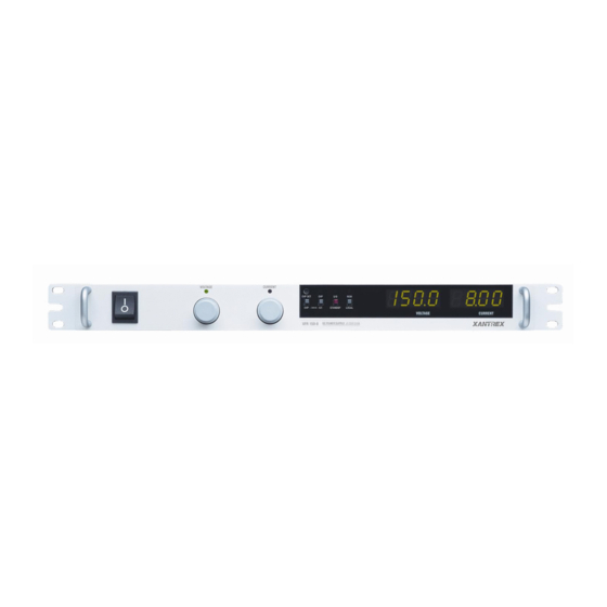
Features and Specifications Front Panel Controls Front Panel Controls See Figure 1.1 to review the controls, LEDs, and meters located on the power supply’s front panel. Check the following sections for additional descriptions of front panel controls and functions. • “Mechanical Specifications”... -
Page 20: Rear Panel Connectors And Switch
Features and Specifications Rear Panel Connectors and Switch Rear Panel Connectors and Switch Use the rear panel SW1 Programming, Monitoring, and Shutdown Select switch and the rear panel J2 Programming and Monitoring connector to choose among several remote programming and monitoring options. See Figure 1.2 for the switches and connectors available at the rear panel. -
Page 21: Rear Panel Sw1 Switch
Features and Specifications Rear Panel Connectors and Switch Rear Panel The SW1 Programming, Monitoring, and Shutdown Select switch is an 8-position piano DIP switch located on the power supply’s rear panel. See Figure 1.3. The SW1 SW1 Switch switch enables you to choose: •... -
Page 22: Rear Panel J2 Connector
Features and Specifications Rear Panel Connectors and Switch Resetting the Switches Before making any changes to the switch settings, disable the power supply output by pushing the front panel STANDBY switch to its IN position. This temporarily shuts down the power supply. The front panel S/D LED turns on. - Page 23 Features and Specifications Rear Panel Connectors and Switch Table 1.3 Rear Panel J2 Connector Terminals and Functions Connector Reference Name Function J2-1 VRMT Remote Output Voltage Selects remote output voltage Programming Select programming when jumpered to pin 3. J2-2 IRMT Remote Output Current Limit Selects remote output current limit Programming Select...
- Page 24 Features and Specifications Rear Panel Connectors and Switch Making J2 Connections CAUTION Do not attempt to bias program/monitor signal return (J2 terminals 5, 7, 9, and 11) relative to the supply output because control ground (J2-3) and the program/monitor signal returns are at the same potential as the power supply return in a standard unit.
-
Page 25: Specifications
Features and Specifications Specifications Specifications These specifications are warranted over a temperature range of 0 °C to 50 °C. Electrical Specifications Nominal ambient temperature assumed is 25 °C. Nominal line voltages are 120 Vac and 230 Vac. See Table 1.4 and Table 1.5 for maximum values for model-dependent specifications. - Page 26 Features and Specifications Specifications Table 1.4 Electrical Specifications for 6 V to 35 V Models Models 6-200 7.5-140 12-100 20-60 35-35 Output Ratings: Output Voltage 0-6 V 0-7.5 V 0-12 V 0-20 V 0-35 V Output Current 0-200 A 0-140 A 0-100 A 0-60 A 0-35 A...
- Page 27 Features and Specifications Specifications 1. Minimum output voltage is <0.15% of rated voltage at zero output setting. 2. Minimum output current is <0.5% of model-rated current at zero output setting, when measured on minimum 10% of full power load. 3. For rack mounted 6 V models, derate output current by 1.5 A per °C for operating temperatures between 30 °C and “Environmental Specification”...
- Page 28 Features and Specifications Specifications Table 1.5 Electrical Specifications for 40 V to 600 V Models Models 40-30 60-20 100-12 150-8 300-4 600-2 Output Ratings: Output Voltage 0-40 V 0-60 V 0-100 V 0-150 V 0-300 V 0-600 V Output Current 0-30 A 0-20 A 0-12 A...
- Page 29 Features and Specifications Specifications 1. Minimum output voltage is <0.15% of rated voltage at zero output setting. 2. Minimum output current is <0.5% of model-rated current at zero output setting, when measured on minimum 10% of full power load. 3. For input voltage variation over the AC input voltage range, with constant rated load. 4.
-
Page 30: Additional Specifications
Features and Specifications Specifications Additional Specifications Rise Time (No Load, Full Load): 6 V to 60 V models: 100 ms; 100 V to 600 V models: 170 ms Fall Time (No Load): 6 V model: 1.5 s; 7.5 V to 60 V models: 3 s; 100 V to 600 V models: 4 s Fall Time (Full Load): 6 V model: 10 ms;... -
Page 31: Figure 1.5 Typical Input Current Characteristics, 85-130 Vac Range
Features and Specifications Specifications 100% at 85 Vac 100% at 130 Vac 50% at 85 Vac 50% at 130 Vac 100% OUTPUT VOLTAGE Figure 1.5 Typical Input Current Characteristics, 85-130 Vac Range (Based on 60 V, 20 A model.) 100% at 190 Vac 100% at 264 Vac 50% at 190 Vac 50% at 264 Vac... -
Page 32: Additional Features
Features and Specifications Specifications Additional Features Switching Frequency 6 V to 40 V models: nominal 78 kHz (156 kHz output ripple); 60 V to 600 V models: nominal 62.5 kHz (125 kHz output ripple). Output Hold-up Time Greater than 20 ms (6 V model: 16 ms) with interruption of AC line, for nominal AC input and full load. -
Page 33: Remote Programming And Monitoring
Features and Specifications Specifications Remote Programming Monitoring Remote Start/Stop and Interlock 2.5-15 V signal or TTL-compatible input, selectable logic. TTL input impedance: 2 k (in series with one diode drop). Remote Analog Programming (Full Voltage and current programming inputs Scale Input) (source must be isolated): 0-5 k, 0-10 k resistances;... -
Page 34: Environmental Specification
Features and Specifications Specifications Environmental Specification Operating Temperature Range 0 °C to 50 °C. 6 V model: for rack mounted units, derate output current by 1.5 A per °C for operating temperatures between 30 °C and 50 °C. See Figure 1.7. Storage Temperature Range -20 °C to +70 °C Humidity Range... -
Page 35: Mechanical Specifications
Features and Specifications Specifications Mechanical Specifications Front Panel V and I Control 10-turn voltage and current potentiometers Front Panel Voltage Control 0.02% of maximum voltage Resolution Front Panel Voltage and Current 3.5-digit green numeric LED displays. For Meters accuracy specifications, see Table 1.4 and Table 1.5. -
Page 36: Figure 1.8 Dimensional Drawings
Features and Specifications Specifications Fuses are located on the A4 PCB (printed circuit board). The fuses are NOT operator-replaceable. 19 in. (483 mm) 1.71 in. (43.4 mm) 16.9 in. (429mm) 20 in. (508 mm) 20" (508 mm) 17.475 in. (444 mm) 1 in. -
Page 37: Introduction
Section 2. Installation Introduction This section provides recommendations and procedures for inspecting, installing, and testing the power supply. Basic Setup Procedure See Table 2.1 for a summary of the basic setup procedure and an overall view of the subsections in this section. Use the procedure as a quick reference if you are familiar with the installation requirements for the power supply. -
Page 38: Inspection, Cleaning, And Packaging
Installation Inspection, Cleaning, and Packaging Inspection, Cleaning, and Packaging Initial When you first receive your unit, perform a quick physical check. Inspection 1. Inspect the unit for scratches and cracks, and for broken switches, connectors, and displays. 2. Ensure that the packing box contains the AC input cover and strain relief kit (see Figure 2.2). -
Page 39: Returning Power Supplies To The Manufacturer
Returning Power Supplies to the Manufacturer Returning Power Supplies to the Manufacturer Return Before returning a product directly to Xantrex you must obtain a Return Material Authorization (RMA) number and the correct factory “Ship To” address. Products Material must also be shipped prepaid. Product shipments will be refused and returned at your... -
Page 40: Packaging For Shipping Or Storage
Installation Returning Power Supplies to the Manufacturer Packaging for Follow these instructions to prepare the unit for shipping or storage. Shipping or 1. When returning the unit or sending it to the service center, attach a tag to the unit Storage stating its model number (available from the front panel label) and its serial number (available from the rear panel label). -
Page 41: Location, Mounting, And Ventilation
Installation Location, Mounting, and Ventilation Location, Mounting, and Ventilation Use the power supply in rack-mounted or in benchtop applications. Rack Mounting WARNING Ensure that any mounting screws do not penetrate more than 1/8 in. (3.0 mm) into the sides of the unit. The power supply is designed to fit in a standard 1 in. -
Page 42: Ac Input Power Connection
Installation AC Input Power Connection AC Input Power Connection WARNING Disconnect AC power from the unit before removing the cover. Even with the front panel power switch in the OFF position, live line voltages are exposed when the cover is removed. Repairs must be made by experienced service technicians only. -
Page 43: Ac Input Cord
Installation AC Input Power Connection Table 2.2 Operational AC Input Voltage Ranges and Frequency AC Voltage Range Frequency 85-130 Vac 1 (20 A maximum at 120 Vac) 47-63 Hz φ 190-264 Vac 1 (12 A maximum at 230 Vac) 47-63 Hz φ... -
Page 44: Figure 2.2 Ac Input Cover And Strain Relief
Installation AC Input Power Connection 3. Slide the helix-shaped body onto the AC cable. Insert the stripped wires through the strain relief base until the outer cable jacket is flush with the edge of the base. Tighten the body to the base while holding the cable in place. The cable is now securely fastened inside the strain relief. -
Page 45: Functional Tests
Installation Functional Tests Functional Tests These functional test procedures include power-on and front panel function checks as well as voltage and current mode operation checks. • Equipment Digital voltmeter (DVM) rated better than 0.5% accuracy. Required • DC shunt 1mV/A (±0.25%) with connecting wire. The recommended current ratings for the DC shunt and the wire must be at least 10% more than the output current of the power supply. -
Page 46: Current Mode Operation Check
Installation Functional Tests Current Mode 1. Ensure that the front panel power switch is set to OFF. Operation 2. Turn the voltage and current controls on the front panel fully counter-clockwise. Check 3. Connect the DC shunt across the output terminals on the rear panel. 4. -
Page 47: Load Connection
Installation Load Connection Load Connection This section provides recommendations for load wires and how to connect them for both single and multiple load configurations. Load Wiring To select wiring for connecting the load to the power supply, consider the following factors: •... -
Page 48: Figure 2.3 Maximum Load Wire Length For 1 V Line Drop
Installation Load Connection Load Wiring Length for Operation with Sense Lines For applications using remote sensing, you must limit the voltage drop across each load line. Figure 2.3 shows some maximum allowable wire lengths for a given load current and wire size. We recommend that you use the larger load wiring to ensure a smaller voltage drop (1 V typical maximum), although units will compensate for up to 5 V drop in each line. -
Page 49: Making Load Connections
Installation Load Connection Making Load Connections WARNING There is a shock hazard at the load when using a power supply with a rated output greater than 40 V. To protect personnel against accidental contact with hazardous voltages, ensure that the load, including connections, has no live parts which are accessible. -
Page 50: Figure 2.5 Typical Load Connection Hardware
Installation Load Connection To make load connections to a 7.5 V, 140 A power supply: 1. Install a connecting wire terminal lug to load wiring (see Figure 2.5). 2. Fasten wire terminal lugs to bus bars with 1/4 in. x 1/2 in. (M6 x 12 mm) screws, 1/4 in. -
Page 51: Figure 2.6 Output Voltage Connector With Shield
Installation Load Connection The 60 V to 600 V (high voltage) models have a 4-terminal, wire clamp output connector. See inset of Figure 2.6 for a labelled drawing of the wire clamp connector. The units are shipped with a protective shield attached (see Figure 2.6). To prepare and connect the load wiring: 3. -
Page 52: Inductive Loads
Installation Load Connection Inductive To prevent damage to the power supply from inductive kickback, connect a diode across the output. The diode must be rated at greater than or equal to the supply’s Loads output voltage and have a current surge rating greater than or equal to the supply’s output rating. -
Page 53: Connecting Multiple Loads
Installation Load Connection Connecting Proper connection of distributed loads is an important aspect of power supply use. Two common methods of connection are the parallel power distribution method and Multiple the radial power distribution method. Loads Parallel Power Distribution This distribution method involves connecting leads from the power supply to one load, from that load to the next load, and so on for each load in the system. -
Page 54: Figure 2.10 Multiple Loads With Remote Sensing
Installation Load Connection Figure 2.10 Multiple Loads with Remote Sensing Operating Manual for XFR 1.2kW Series Power Supply... -
Page 55: Local And Remote Sensing
Installation Local and Remote Sensing Local and Remote Sensing Use connections at the rear panel J10 sense connector to configure the power supply for local or remote sensing of output voltage. See Figure 2.11 for a drawing of the sense connector. Sense Wiring WARNING There is a potential shock hazard at the sense connector when using a power... -
Page 56: Using Remote Sensing
Installation Local and Remote Sensing Table 2.5 Rear Panel J10 Sense Connector Terminals and Functions Terminal Name Function J10-1 Return Sense (–SNS) Remote negative sense connection. Default connection to terminal 2. J10-2 Negative Output (Return or RTN) Connected internally to negative output. J10-3 No connection. - Page 57 Installation Local and Remote Sensing To connect remote sense lines: 1. Turn OFF the power supply. 2. Remove the local sense jumpers connecting J10 mating connector terminal 5 (positive sense) to terminal 4 (positive output) and terminal 1 (return sense) to terminal 2 (power supply return).
-
Page 58: Figure 2.12Connecting Remote Sense Lines
Installation Local and Remote Sensing Figure 2.12Connecting Remote Sense Lines Operating Manual for XFR 1.2kW Series Power Supply... -
Page 59: Introduction
Section 3. Local Operation Introduction Once you have installed the power supply and have connected both the AC input power and the load as covered in Section 2. Installation, the power supply is ready to operate in local control mode (that is, operation at the unit’s front panel). •... -
Page 60: Figure 3.1 Operating Modes
Local Operation Standard Operation Output Voltage > Constant Voltage Mode Region Crossover Point V SET < Constant Current Mode Region Where: = Load Resistance = Output Voltage Setting Output Current = Output Current Setting I SET Figure 3.1 Operating Modes Constant Voltage Mode Operation The power supply will operate in constant voltage mode whenever the load current I is less than the current limit setting I... -
Page 61: Shipped Configuration
Local Operation Standard Operation Shipped The factory ships units already configured for local control (front panel) operation. Configuration See Table 3.1 for a summary of this configuration. Table 3.1 Shipped Configuration (Local Control Mode) Local Control Configuration Additional References Use the front panel controls to adjust the output See Section 3 for front panel voltage and current limit settings. -
Page 62: Setting Output Voltage And Current Limit
Local Operation Standard Operation Setting Install the power supply and connect the load as described in Section 2. Installation. Ensure that the power supply is set up for local control as described in “Shipped Output Configuration” on page 59. Then, set the output voltage and current limit at the front Voltage and panel with the following procedure. -
Page 63: Using Over Voltage Protection (Ovp)
Local Operation Using Over Voltage Protection (OVP) Using Over Voltage Protection (OVP) The OVP circuit protects the load in the event of a remote programming error, an incorrect voltage control adjustment, or a power supply failure. The protection circuit monitors the output voltage at the output of the power supply and will shut down the main power converter whenever a preset voltage limit is exceeded. -
Page 64: Resetting The Ovp Circuit
Local Operation Using Over Voltage Protection (OVP) Resetting the To reset the OVP circuit after it activates: OVP Circuit 1. Reduce the power supply’s output voltage setting to below the OVP set point. 2. Press the STANDBY switch IN. The red S/D LED on the front panel turns on. The OVP LED turns off. -
Page 65: Using The Shutdown Function
Local Operation Using the Shutdown Function Using the Shutdown Function Use the shutdown function to disable or enable the supply’s output so that you can make adjustments to either the load or the power supply without shutting off the power supply. Activate this function from the front panel at any time by using the STANDBY switch. - Page 66 Local Operation Using the Shutdown Function Table 3.2 Switch Settings for Shutdown Circuit Logic Switch SW1-7 Setting Source Signal Signal Level Supply Output S/D LED OFF (OPEN) 2-15 V HIGH (Active low, default) 0-0.4 V ON (CLOSED) 2-15 V HIGH (Active high) 0-0.4 V If switch SW1-7 is ON but there is no signal applied, the S/D LED turns on and...
-
Page 67: Using Multiple Supplies
Local Operation Using Multiple Supplies Using Multiple Supplies WARNING There is a shock hazard at the load when using a power supply with a rated or combined output greater than 40 V. To protect personnel against accidental contact with hazardous voltages created by series connection, ensure that the load, including connections, has no live parts which are accessible. -
Page 68: Configuring Multiple Supplies For Series Operation
Local Operation Using Multiple Supplies Configuring Multiple Supplies for CAUTION Do not use remote sensing during series operation. Series Operation CAUTION The maximum allowable sum of the output voltages is 600 Vdc. Use series operation to obtain a single higher voltage output using two or more supplies. -
Page 69: Configuring Multiple Supplies For Parallel Operation
Local Operation Using Multiple Supplies Configuring Use parallel operation to obtain a higher current through a single output using two or more supplies. Set all of the OVP setpoints to maximum. (See “Using Over Voltage Multiple Protection (OVP)” on page 61.) Set all of the outputs to the same voltage before Supplies for connecting the positive (+) output terminals and negative (–) output terminals in Parallel... -
Page 70: Configuring Multiple Supplies For Split Supply Operation
Local Operation Using Multiple Supplies Configuring Split supply operation uses two power supplies to obtain two positive voltages with a common ground, or to obtain a positive-negative supply. Multiple Supplies for Two Positive Voltages To obtain two positive voltages, connect the negative Split Supply output terminals of both supplies together in a common connection. -
Page 71: Figure 3.5 Split Supply Operation Of Multiple Supplies
Local Operation Using Multiple Supplies Figure 3.5 Split Supply Operation of Multiple Supplies (Positive-negative Supply) (Local sense lines shown are default J10 connections.) Release 3.1... -
Page 72: Over Temperature Protection (Otp)
Local Operation Over Temperature Protection (OTP) Over Temperature Protection (OTP) The OTP function allows you to select how the power supply recovers from an over temperature shutdown using the rear panel switch SW1-8. See Table 3.3 for the switch settings and selections. See “Rear Panel Connectors and Switch” on page 18 for more information about the switch. -
Page 73: User Diagnostics
Local Operation User Diagnostics User Diagnostics If your power supply is not performing as described in this manual, run through the procedures and checks in this section before calling your service technician. These procedures are confined to operator level functions only and do not require cover-off servicing. - Page 74 Local Operation User Diagnostics Table 3.4 User Diagnostics Symptom Check Further Checks and Corrections No output and the Is input voltage within specified Connect to appropriate voltage source. display is blank. range? See page 40. Power switch ON? Turn on power. Internal circuit? See your service technician.
-
Page 75: Introduction
Section 4. Remote Operation Introduction The rear panel switches and connector on the power supply allow you to program the supply with an analog device or to output readback signals. This section covers the following topics: • See “Remote Analog Programming of Output Voltage and Current Limit” on page 74 for procedures covering remote analog programming of output voltage and current limit with 0-5 V and 0-10 V voltage sources and 0-5 k and 0-10 k resistances. -
Page 76: Remote Analog Programming Of Output Voltage And Current Limit
Remote Operation Remote Analog Programming of Output Voltage and Current Limit Remote Analog Programming of Output Voltage and Current Limit Remote analog programming allows control of the power supply’s output voltage and/or current limit to shift from local operation at the front panel voltage and current controls to external analog sources. - Page 77 Remote Operation Remote Analog Programming of Output Voltage and Current Limit 5. Set the programming sources to the desired levels and turn the power supply ON. The REM LED turns on. Adjust the external programming source to change the power supply’s output. Please remember: 1.
- Page 78 Remote Operation Remote Analog Programming of Output Voltage and Current Limit Table 4.2 Power Supply Settings for Different Programming Sources Output Output Current Limit Programming Source Voltage 0-5 Vdc 0-10 Vdc 0-5 k Resistor 0-10 k Resistor None (Front Programming Panel Control) Source 0-5 Vdc...
-
Page 79: Figure 4.1 Connecting Programming Sources To J2 Connector
Remote Operation Remote Analog Programming of Output Voltage and Current Limit Figure 4.1 Connecting Programming Sources to J2 Connector Release 3.1... -
Page 80: Remote Monitoring Of Output Voltage And Current
Remote Operation Remote Monitoring of Output Voltage and Current Remote Monitoring of Output Voltage and Current Readback The J2 connector on the rear panel provides access to calibrated readback signals for remote monitoring of the output voltage and current. Rear panel switches SW1-5 and Signals SW1-6 allow you to select either a 0-5 Vdc or a 0-10 Vdc range for the output. -
Page 81: Introduction
Section 5. Calibration Introduction WARNING HIGH ENERGY AND HIGH VOLTAGE WARNING Exercise caution when using and calibrating a power supply. High energy levels can be stored at the output voltage terminals on a power supply in normal operation. In addition, potentially lethal voltages exist in the power circuit and on the output and sense connectors of a power supply with a rated output greater than 40 V. -
Page 82: Accessing Calibration Potentiometer
Calibration Calibration Setup Accessing Calibration Potentiometer WARNING Disconnect AC power from the unit before removing the cover. Even with the front panel power switch in the OFF position, live line voltages are exposed when the cover is removed. Repairs and adjustments must be made by experienced service technicians only. -
Page 83: Calibration Calibration Setup
Calibration Calibration Setup Figure 5.1 Programming and Monitoring Calibration Locations (Top view.) Release 3.1... -
Page 84: Calibrating For Programming Accuracy
Calibration Calibrating for Programming Accuracy Calibrating for Programming Accuracy The factory calibrates the offset and range of the voltage and current programming circuits to within 1% for the default 0-10 Vdc programming signals. You may need to recalibrate when you use 0-5 Vdc programming or when you switch back to 0-10 Vdc programming after previously calibrating for 0-5 Vdc programming. -
Page 85: Current Limit Programming Circuit Calibration
Calibration Calibrating for Programming Accuracy Current Limit 1. Ensure that the power supply is turned OFF. Disconnect any load. Programming 2. Connect the program source between J2 connector terminals 8 (output current Circuit limit programming input) and 7 (current program signal return). Calibration 3. -
Page 86: Calibrating For Readback Accuracy
Calibration Calibrating for Readback Accuracy Calibrating for Readback Accuracy The factory calibrates the offset and range of the output voltage and current monitor circuits to within 1% for the default 0-10 Vdc scales. You may need to recalibrate when you select the 0-5 Vdc scale or when you switch back to the 0-10 Vdc scale after previously calibrating for 0-5 Vdc operation. -
Page 87: Output Current Monitor Circuit Calibration
Calibration Calibrating for Readback Accuracy Output 1. Ensure that the power supply is turned OFF. Disconnect any load. Current 2. Set SW1 switch 6 OPEN to select 0-5 V output current monitor range, CLOSED Monitor for 0-10 V. Circuit 3. Connect the shunt and DVM across the power supply output to read the output Calibration current. - Page 88 Calibration Calibrating for Readback Accuracy Operating Manual for XFR 1.2kW Series Power Supply...
- Page 90 Xantrex Technology Inc. 8999 Nelson Way Burnaby, British Columbia Canada V5A 4B5 604 422 8595 Tel 604 421 3056 Fax 800 667 8422 Toll Free North America prg.info@xantrex.com www.xantrex.com TM-F1OP-C1XN PRINTED IN CANADA...