Table of Contents
Advertisement
Available languages
Available languages
Quick Links
Advertisement
Table of Contents

Related Manuals for Xantrex XPH 35-5


Summary of Contents for Xantrex XPH 35-5
-
Page 1: Power Supply
XPH 35-5 Operating Manual XPH Series 35V 5A DC Power Supply... -
Page 2: Contact Information
Trademarks XPH series is a trademark of Xantrex International. Xantrex is a registered trademark of Xantrex International. Other trademarks, registered trademarks, and product names are the property of their respective owners and are used herein for identification purposes only. -
Page 3: Table Of Contents
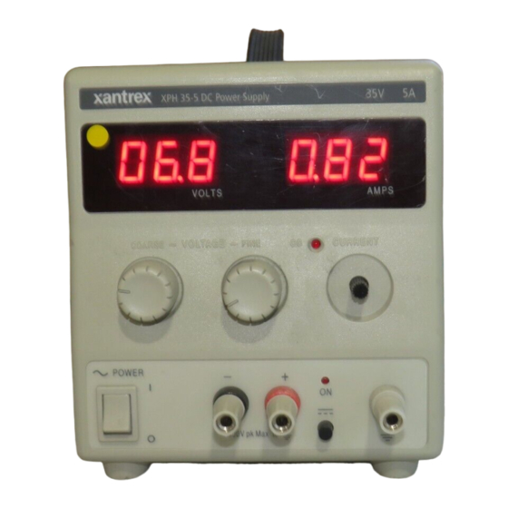
Introduction The XPH 35-5 is an exceptionally compact and lightweight single output laboratory dc power supply providing 0 to 35V at 0 to 5A. The XPH 35-5 uses mixed−mode regulation technology which combines switch−mode pre−regulation with linear post−regulation. Special techniques are used to maintain very high efficiency whilst achieving noise levels that are close to that of a pure linear regulator. -
Page 4: Specification
Specification OUTPUT Voltage Range: 0V to 35V minimum Current Range: 0A to 5A minimum Output Voltage Setting: By coarse and fine controls. Output Current Setting: By single logarithmic control. Operating Mode: Constant voltage or constant current with automatic cross-over. Output Switch: Electronic. -
Page 5: Safety
Safety This power supply is a Safety Class I instrument according to IEC classification and has been designed to meet the requirements of EN61010-1 (Safety Requirements for Electrical Equipment for Measurement, Control and Laboratory Use). It is an Installation Category II instrument intended for operation from a normal single phase supply. -
Page 6: Emc
This instrument has been designed to meet the requirements of the EMC Directive 89/336/EEC. Compliance was demonstrated by meeting the test limits of the following standards: Emissions EN61326 (1998) EMC product standard for Electrical Equipment for Measurement, Control and Laboratory Use. Test limits used were: Radiated : Class B Conducted : Class B Harmonics: EN61000-3-2 (2000) Class A;... -
Page 7: Installation
Installation Mains Operating Voltage This instrument has a universal input range and will operate from a nominal 115V or 230V mains supply without adjustment. Check that the local supply meets the AC Input requirement given in the Specification. Mains Lead When a three core mains lead with bare ends is provided this should be connected as follows: BROWN MAINS LIVE... -
Page 8: Operation
Operation Setting Up the Output With the POWER switch on ( ) and the output off the output voltage and current limit can be accurately preset using the VOLTAGE and CURRENT controls; the left-hand meter shows the set voltage and the right-hand meter shows the set maximum current. When the output switch is switched on, the ON lamp lights;... -
Page 9: Maintenance
Note that the output terminals are rated at 15A maximum; if several outputs are operated in parallel to source higher currents than this the junction should be made at a separate point, not one of the terminals. Ventilation The power supply is very efficient but nevertheless can generate significant heat at full power. The supply relies on convection cooling only and it is therefore important that ventilation is never restricted if performance and safety are to be maintained. -
Page 10: Calibration
Calibration Allow at least 5 minutes warm-up before commencing calibration. Access to Calibration Adjustments All adjustments are on the front panel control board; all the trimmers are adjusted from the reverse side of the board through holes in the board. To gain access to the board it is necessary to remove the top cover. -
Page 11: Current Calibration
Current Calibration Switch output OFF. Set output voltage to nominally 2V. Set current control to minimum. Connect the DMM (set to Amps) and load in series across the output. Switch output ON. Adjust VR8 (offset compensation of current control error amp) for a reading of 0.003A ±... - Page 12 Sécurité Cet instrument est de Classe de sécurité 1 suivant la classification IEC et il a été construit pour satisfaire aux impératifs EN61010-1 (impératifs de sécurité pour le matériel électrique en vue de mesure, commande et utilisation en laboratoire). Il s'agit d'un instrument d'installation Catégorie II devant être exploité...
- Page 13 Installation Tension d’utilisation secteur Cet instrument a une plage d'entrée universelle et il fonctionne sur une alimentation secteur de 115 V ou de 230 V, tension nominale, sans ajustement aucun. Vérifier que l'alimentation locale satisfait aux impératifs d'entrée c.a. indiqués aux Caractéristiques techniques. Câble secteur Relier de la manière suivante tout câble secteur à...
-
Page 14: Bedienungsanleitung Auf Deutsch
Fonctionnement Réglage de la sortie L’interrupteur POWER (alimentation) sur ( ) et la sortie éteinte, il est possible de régler avec précision la limite de tension et de courant de sortie au moyen des commandes VOLTAGE (Tension) et CURRENT (Courant); l’appareil de mesure gauche indique la tension réglée et l’appareil droit le courant maximum réglé. - Page 15 celle du bloc de réglage de tension de sortie le plus élevé, jusqu’à ce que le courant consommé dépasse le réglage de limite de courant, auquel cas la sortie descend à celle du réglage le plus haut suivant, etc. En mode de courant constant, les blocs peuvent être reliés en parallèle, afin de donner un courant égal à...
- Page 16 Sicherheit Dieses Gerät wurde nach der Sicherheitsklasse (Schutzart) I der IEC-Klassifikation und gemäß den europäischen Vorschriften EN61010-1 (Sicherheitsvorschriften für elektrische Meß-, Steuer, Regel- und Laboranlagen) entwickelt. Es handelt sich um ein Gerät der Installationskategorie II, das für den Betrieb von einer normalen einphasigen Versorgung vorgesehen ist. Das Gerät wurde gemäß...
- Page 17 Installation Netzbetriebsspannung Das Gerät besitzt einen universellen Eingangsbereich und kann ohne jede weitere Einstellung mit einer Nenn-Netzversorgung von 115 oder 230 V betrieben werden. Stellen Sie sicher, daß die Versorgung am Ort den in der Spezifikation aufgeführten Eingangsanforderungen entspricht. Netzkabel Steht nur ein Netzkabel ohne Stecker zur Verfügung, so ist es wie folgt anzuschließen: BRAUN STROMFÜHRENDER LEITER...
-
Page 18: Istruzioni In Italiano
Betrieb Einstellung des Ausgangs Bei eingeschaltetem POWER-Schalter (Netz I) und ausgeschaltetem Ausgang läßt sich die Ausgangsspannung und Strombegrenzung mit Hilfe der Knöpfe VOLTAGE (Spannung) und CURRENT (Strom) genau voreinstellen. Die linke Anzeige zeigt die eingestellte Spannung und die rechte den eingestellten Maximalstrom an. Wenn der Ausgangsschalter eingeschaltet wird, leuchtet die ON (Ein)-Leuchte auf. - Page 19 Das Gerät kann zur Erzeugung einer höheren Stromabgabe mit anderen Geräten parallel zu diesen geschaltet werden. Wenn mehrere Geräte parallel geschaltet werden, entspricht die Ausgangsspannung der Ausgangsspannung des Geräts, bei dem der Einstellwert für die Ausgangsspannung am höchsten ist, bis die Stromaufnahme den bei diesem Gerät eingestellten Grenzwert überschreitet, woraufhin der Ausgang auf die zweilhöchste Einstellung abfällt, und so weiter.
- Page 20 Sicurezza Questo strumento appartiene alla Categoria di Sicurezza 1, secondo la classifica IEC, ed è stato progettato in modo da soddisfare i criteri EN61010-1 (requisiti di Sicurezza per Apparecchiature di misura, controllo e per uso in laboratorio). È uno strumento di Categoria d’installazione II ed è inteso per il funzionamento con un’alimentazione normale monofase.
- Page 21 Installazione Tensione d’esercizio Questo strumento è dotato di un’entrata universale e funziona con un’alimentazione a 115V o 230V senza regolazione. Controllare che la rete locale soddisfi i requisiti d’entrata indicati nella specifica. Cavo d’alimentazione Quando viene fornito un cavo a tre fili con le estremità nude, collegare come segue: MARRONE LINEA NEUTRO...
-
Page 22: Instrucciones En Español
Funzionamento Impostazione dell’uscita Con l’interruttore POWER (alimentazione) regolato su ( ) e l’uscita su off (spenta), la tensione di uscita ed il limite di corrente possono essere preimpostati accuratamente usando i comandi VOLTAGE (tensione) e CURRENT (corrente) ; il misuratore di sinistra mostra la tensione impostata mentre quello di destra indica la corrente massima impostata. - Page 23 corrente impostato; a questo punto la tensione in uscita impostata scende al valore dell’impostazione più alta immediatamente inferiore e così via. In modalità di corrente costante, vari gruppi possono essere collegati in parallelo per erogare una corrente uguale alla somma dei limiti di corrente impostati.
- Page 24 Seguridad Este es un instrumento de Clase de Seguridad I según la clasificación del IEC y ha sido diseñado para cumplir con los requisitos del EN61010-1 (Requisitos de Seguridad para Equipos Eléctricos para la Medición, Control y Uso en Laboratorio). Es un instrumento de Categoría de Instalación II propuesto para ser usado con un suministro monofásico normal.
- Page 25 Instalación Tensión de la Red Eléctrica Este instrumento tiene un rango de entrada universal y funcionará sin necesidad de ajustes en suministros eléctricos de 115V o 230V. Compruebe que el suministro local satisface los requisitos de entrada CA que se estipulan en Especificaciones. Cable de Red Cuando se suministra un cable de tres conductores con puntas peladas, se deberá...
- Page 26 Operación Ajuste de la Salida Con el interruptor POWER conectado ( ) y se pueden preajustar la salida de la tensión de salida y el límite de corriente con precisión usando los controles de VOLTAGE y CURRENT; el medidor a la izquierda indica la tensión ajustada y el medidor a la derecha indica la corriente máxima preajustada.
- Page 27 sucesivamente. En la modalidad de corriente constante, las unidades pueden conectarse en paralelo para proporcionar una corriente igual a la suma de los límites de corriente fijados. Se debe observar que la salida de los bornes está clasificada a un máximo de 15A; si varias salidas funcionan en paralelo para suministrar corrientes superiores a ésta, la junta debe efectuarse en un punto distinto y no en los bornes.
-
Page 28: Warranty Information
Direct returns may be performed according to the Xantrex Return Material Authorization Policy described in your product manual. For some products, Xantrex maintains a network of regional Authorized Service Centers. Call Xantrex or check our website to see if your product can be repaired at one of these facilities. - Page 29 Xantrex product specifications including high input voltage from generators and lightning strikes; c) the product if repairs have been done to it other than by Xantrex or its authorized service centers (hereafter "ASCs");...
-
Page 30: Return Material Authorization Policy
2. Include the following: • The RMA number supplied by Xantrex Technology, Inc. clearly marked on the outside of the box. • A return address where the unit can be shipped. Post office boxes are not acceptable. - Page 31 Xantrex Technology Inc. 8999 Nelson Way Burnaby, British Columbia Canada V5A 4B5 604 422 8595 Tel 604 421 3056 Fax 800 667 8422 Toll Free North America prg.info@xantrex.com www.xantrex.com 975-0103-01-02 48511-0730 Issue 2...