
Related Manuals for Endress+Hauser Teqwave F


Summary of Contents for Endress+Hauser Teqwave F
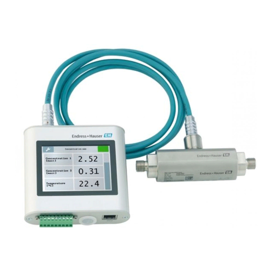
- Page 1 Products Solutions Services BA01823D/06/EN/02.19 71452947 2019-09-10 Valid as of version 2.2.zz (Device firmware) Operating Instructions Teqwave F/I Modbus TCP Measuring device with acoustic surface wave technology...
- Page 2 • The manufacturer reserves the right to modify technical data without prior notice. Your Endress+Hauser Sales Center will supply you with current information and updates to these instructions. Endress+Hauser...
-
Page 3: Table Of Contents
Teqwave F/I Modbus TCP Table of contents Table of contents About this document ....6 Electrical connection ....19 Document function . - Page 4 11.4.2 Graph tools ....50 13.2 Endress+Hauser services ....63 11.4.3 Switching auto scale on and off .
- Page 5 Teqwave F/I Modbus TCP Table of contents 16.15 Documentation ..... . . 75 Index ........76...
-
Page 6: About This Document
About this document Teqwave F/I Modbus TCP About this document Document function These Operating Instructions contain all the information that is required in various phases of the life cycle of the device: from product identification, incoming acceptance and storage, to mounting, connection, operation and commissioning through to troubleshooting, maintenance and disposal. -
Page 7: Symbols For
• W@M Device Viewer (www.endress.com/deviceviewer): Enter the serial number from nameplate • Endress+Hauser Operations App: Enter the serial number from the nameplate or scan the 2D matrix code (QR code) on the nameplate Detailed list of the individual documents along with the documentation code →... -
Page 8: Standard Documentation
About this document Teqwave F/I Modbus TCP 1.3.1 Standard documentation Document type Purpose and content of the document Technical Information Planning aid for your device The document contains all the technical data on the device and provides an overview of the accessories and other products that can be ordered for the device. -
Page 9: Basic Safety Instructions
Teqwave F/I Modbus TCP Basic safety instructions Basic safety instructions Requirements for the personnel The personnel for installation, commissioning, diagnostics and maintenance must fulfill the following requirements: ‣ Trained, qualified specialists must have a relevant qualification for this specific function and task. -
Page 10: Operational Safety
Conversions to the device Unauthorized modifications to the device are not permitted and can lead to unforeseeable dangers. ‣ If, despite this, modifications are required, consult with Endress+Hauser. Repair To ensure continued operational safety and reliability, ‣ Carry out repairs on the device only if they are expressly permitted. -
Page 11: Product Description
Teqwave F/I Modbus TCP Product description Product description The measuring system consists of a sensor and a transmitter. The sensor and transmitter are mounted in physically separate locations. A connecting cable with a push-pull connector interconnects the sensor and transmitter. -
Page 12: Transmitter
Applicator → 67. If you require a concentration app that is not already listed in the Applicator, Endress+Hauser requires a sample of the fluid to create the concentration app. Every transmitter can use a maximum of 25 concentration apps. -
Page 13: Incoming Acceptance And Product
Is a CD-ROM provided with the Technical Documentation (depends on device version) and documents? • If one of the conditions is not satisfied, contact your Endress+Hauser Sales Center. • Depending on the device version, the CD-ROM might not be part of the delivery! The Technical Documentation is available via the Internet or via the Endress+Hauser Operations App, see the "Product identification"... -
Page 14: Nameplate
Incoming acceptance and product identification Teqwave F/I Modbus TCP 4.2.1 Nameplate Order code: Ser. no.: Ext. ord. cd.: Device ID FW Device Rev. A0035638 3 Example of a nameplate on a transmitter Place of manufacture Order code Serial number (Ser. no.) Extended order code (Ext. -
Page 15: Storage And Transport
Teqwave F/I Modbus TCP Storage and transport Storage and transport Storage conditions Observe the following notes for storage: • store in the original packaging to ensure protection from shock • protect from direct sunlight to avoid unacceptably high surface temperatures •... -
Page 16: Installation
Installation Teqwave F/I Modbus TCP Installation Mounting requirements 6.1.1 Mounting position Mounting location A0032998 4 Mounting location Ideally, the sensor should be installed in an ascending pipe, while ensuring a sufficient distance is kept to the next pipe elbow: h ≥ 5 × DN. -
Page 17: Mounting The Measuring Device
‣ Use clean, undamaged seals only. ‣ Secure the seals correctly. Mounting the sensor: Teqwave F NOTICE Damage to the sensor Twisting the sensor when tightening the threaded joints can damage the sensor. ‣ When tightening the threaded joint, always use a second open-ended wrench or pipe wrench to apply counter-pressure (prevents twisting). -
Page 18: Mounting The Transmitter
Installation Teqwave F/I Modbus TCP 6.2.2 Mounting the transmitter A0035459 7 Mounting the transmitter DIN rail holder DIN rail according to DIN EN 60715 TH 35 Mount the transmitter on the DIN rail using the DIN rail holder. Post-mounting check... -
Page 19: Electrical Connection
Teqwave F/I Modbus TCP Electrical connection Electrical connection The measuring device does not have an internal circuit breaker. For this reason, assign the measuring device a switch or power-circuit breaker that allows the power supply line to be easily disconnected from the mains. -
Page 20: Requirements For Supply Unit
Electrical connection Teqwave F/I Modbus TCP Terminal Assignment alarm Relay output max. 50 V, 1 A 7.1.3 Requirements for supply unit Supply voltage DC 24 V (nominal voltage: DC 18 to 35 V) Power unit The power unit must be tested to ensure it meets safety requirements (e.g. PELV, SELV). -
Page 21: Connecting The Signal Cables
Teqwave F/I Modbus TCP Electrical connection 7.2.3 Connecting the signal cables The signal can be transmitted using analog technology via the analog output and using digital technology via Ethernet (Modbus protocol). The connection to the "Teqwave Viewer" operating tool is also established via the Ethernet interface. - Page 22 Electrical connection Teqwave F/I Modbus TCP Relay output A0035461 11 Connection example for relay output, passive Automation system with switch input (e.g. PLC) Power supply: max. 50 V AC/DC Transmitter Digital input (elective inputs) The digital input can create up to four measured variables on the analog output.
-
Page 23: Post-Connection Check
Teqwave F/I Modbus TCP Electrical connection Post-connection check Are the cables and measuring device undamaged (visual inspection)? Do the cables used comply with the requirements ? Do the cables have adequate strain relief? Are all the connectors firmly seated? ... -
Page 24: Operating Options
Operating options Teqwave F/I Modbus TCP Operating options Overview of the operating options The measuring device can be operated in the following ways: • Operation via the local display (transmitter with touch screen) • Operation via the "Teqwave Viewer" operating tool supplied... - Page 25 Teqwave F/I Modbus TCP Operating options Functions of the display and operating elements Button Description Settings menu Opens the settings. Navigation Navigate between the menus or submenus. Status indication Indicates the current status, and navigation to more detailed status messages in text format.
-
Page 26: Led Status Indication (Transmitter With Led Status Indication)
Operating options Teqwave F/I Modbus TCP Input mask The following input symbols are available in the input mask of the numeric and text editor: Input and operating symbols in the editors Symbol Meaning Selection of letters from A to Z …... -
Page 27: System Requirements
Teqwave F/I Modbus TCP Operating options 8.3.1 System requirements Computer hardware Interface The computer must have an Ethernet RJ45 interface. Connection Standard Ethernet cable with RJ45 connector. Screen Recommended screen resolution: min. 1024 x 768 pixels. Computer software Recommended operating system Microsoft Windows 7 or higher. - Page 28 Operating options Teqwave F/I Modbus TCP 6. Settings menu → "Network settings" → "Gateway" 7. Settings menu → "Network settings" → "DHCP" Navigation using the Viewer 1. Menu "Teqwave Transmitter" → "Network settings" → "IP address" 2. Menu "Teqwave Transmitter" → "Network settings" → "Subnet mask"...
-
Page 29: User Interface
Teqwave F/I Modbus TCP Operating options Parameter Description Selection/entry/display Factory setting Gateway Enter the IP address for a Character string with the 0.0.0.0 gateway in the local following format: w.x.y.z network. DHCP (transmitter) Enable DHCP to allow the Enable or disable the... -
Page 30: General Control And Operating Elements
Operating options Teqwave F/I Modbus TCP A0035470-EN 14 User interface Menu bar Measured variable display Status indication IP address Graph Menu bar Menu Description File Functions for starting and stopping measured value transmission and for saving the graph. Teqwave Viewer Functions that are required to configure the operating tool. - Page 31 Teqwave F/I Modbus TCP Operating options Button Description Close button Exit the function. A0035495-EN Active button Enable function or parameter. A bright-green arrow A0035496 indicates that functions and parameters are enabled. Inactive button Disable function or parameter. A dark-green arrow A0035497 indicates that functions and parameters are disabled.
-
Page 32: System Integration
System integration Teqwave F/I Modbus TCP System integration Overview of device description files Current version data for the device Firmware version 2.2.zz • On title page of the Operating Instructions • On nameplate • On local display: settings • Via "Teqwave Viewer" operating tool: Help →... - Page 33 Teqwave F/I Modbus TCP System integration Register name Data type Register address Length Density / kg/m³ IEEE754 32bit 0x0014:0x0015 Dispersion IEEE754 32bit 0x001A:0x001B System status 32bit unsigned 0x0050:0x0051 While values are transmitted in "big-endian" format during Modbus communication, in line with specifications, the content of the registers is saved in "little-endian" format for performance reasons.
-
Page 34: Commissioning
Commissioning Teqwave F/I Modbus TCP Commissioning NOTICE Damage to the touch surface Sharp objects, electrostatic discharge, water and the use of pens not designed for touch screens, such as standard pencils, can cause a malfunction of touch-control transmitters or damage the touch surface. -
Page 35: Selecting The Concentration App
Teqwave F/I Modbus TCP Commissioning 10.4.1 Selecting the concentration app A concentration app is enabled via the menu Select concentration app (transmitter with a touch screen) or Manage concentration app (Viewer). Navigation using transmitter with touch screen Settings menu → "Select concentration app"... -
Page 36: Configuring The Analog Output
Commissioning Teqwave F/I Modbus TCP Navigation using transmitter with touch screen • Settings menu → "Application parameter" → "Measuring unit" → "Concentration 1-2" • Settings menu → "Application parameter" → "Measuring unit" → "Temperature" • Settings menu → "Application parameter" → "Measuring unit" → "Density"... - Page 37 Teqwave F/I Modbus TCP Commissioning Parameter overview with brief description Parameter Procedure Selection/input Factory setting Analog channel 1-4 Select the measured variable or • Concentration 1-2 Concentration 1 special function to be output at the • Temperature analog output. • Speed of sound •...
-
Page 38: Configuring The Measuring Range
Commissioning Teqwave F/I Modbus TCP 10.4.5 Configuring the measuring range The Measurement range menu contains parameters for configuring the measuring range. • The settings made in this menu also apply for the functions of the analog output, where they define the minimum (0 V/4 mA and maximum (10 V/20 mA). - Page 39 Teqwave F/I Modbus TCP Commissioning 2. Settings menu → "Application parameters" → "Relay output" → "Settings" → "Select measured value" → "Switch point Max"/"Switch point Min" or "Switch point" 3. Settings menu → "Application parameters" → "Relay output" → "Settings" → "Select measured value"...
- Page 40 Commissioning Teqwave F/I Modbus TCP Parameter overview with brief description Parameter Procedure Selection/input Factory setting Output mode Select the mode for the switch point • Range mode Range mode definition. • Trigger mode If Range mode is selected, enter the upper and lower limit to define the switch points.
-
Page 41: Configuring The Measured Value
Teqwave F/I Modbus TCP Commissioning Parameter Procedure Selection/input Factory setting Switch point Min Prerequisite: Positive decimal • Concentration 1-2: 0.00 Range mode is selected in the • Temperature: 0.00 Output mode parameter. • Speed of sound: 500.00 Set the lower limit at which the •... -
Page 42: Configuring The Touch Screen
Commissioning Teqwave F/I Modbus TCP Parameter overview with brief description Parameter Procedure Selection/input Factory setting Display settings Transmitter • Concentration 1-2 All the Tap the measured variable to show or hide it on the transmitter' s operational display. • Temperature measured •... -
Page 43: Configuring The Failsafe Mode
Teqwave F/I Modbus TCP Commissioning Parameter overview with brief description Parameter Procedure Selection/input Factory setting Brightness Enter screen brightness. 20 to 100 % 100 % If the screensaver is enabled, the value entered here must be greater than the minimum value for the screensaver. -
Page 44: Advanced Settings
Commissioning Teqwave F/I Modbus TCP 2. Settings menu → "Application parameters" → "Diagnosis" → "Change in → Select measured variable 3. Settings menu → "Application parameters" → "Diagnosis" → "Process disturbance" → "Switch point" Navigation using the Viewer 1. Menu "Teqwave Transmitter" → "View filter" → "Filter options" and "Filter actions"... -
Page 45: Performing Field Calibration With A
Up to two calibration points can be recorded. If a two-point calibration is performed, Endress+Hauser recommends recording two different states of the liquid. Different states can be different temperatures or concentrations. The process conditions must remain constant here. If necessary, remove a calibration point with the "Delete calibration point"... -
Page 46: Application Package "Viewer With Interface For Data Download
10.6.2 Activation Endress+Hauser provides users with a license key to activate the functions. The license key must be entered to enable the functions of the application package. The key is entered in the Viewer via the "Teqwave Transmitter" → "License key" menu. - Page 47 Teqwave F/I Modbus TCP Commissioning Parameter overview with brief description Parameter Procedure Selection/input Factory setting Storage interval (s) Select the time interval in Positive integer 60 s which the measured 10 to 7 200 s values are written to the internal memory.
-
Page 48: Operation
Operation Teqwave F/I Modbus TCP Operation 11.1 Adjusting the operating language Operating language settings → 34. 11.2 Configuring the local display Local display settings → 42. 11.3 Reading measured values via the local display All the current measured values can be read via the operational display of the transmitter with a touch screen. -
Page 49: Graph Tools
Teqwave F/I Modbus TCP Operation 11.3.2 Graph tools Button Description Settings Navigate to the graph settings. Cursor position Select the cursor position in the graph for the desired measured value display. Clear Clears the graph. The graph representation then resumes. -
Page 50: Graph Tools
Operation Teqwave F/I Modbus TCP Parameter Procedure Selection/input Factory setting Y-axis 2 Select measured variables to be • Concentration 1 Temperature displayed on the right-side axis. • Concentration 2 • Temperature • Speed of sound • Density • Dispersion Time interval in seconds... -
Page 51: Saving The Current Measuring Point
Teqwave F/I Modbus TCP Operation 11.5.1 Saving the current measuring point to a .csv file 1. Select the menu "Teqwave Viewer" → "Single measurement". The "Specify path" window opens. 2. Select the file where the measuring point is to be saved. Either create a new or select an existing .csv file on the computer. -
Page 52: Reading Measured Data From The Transmitter
Operation Teqwave F/I Modbus TCP The Viewer can read out and delete measured data recorded during the operation of the transmitter with the Read memory function. The Viewer saves the data wit the Save read data function. 11.7.1 Reading measured data from the transmitter 1. -
Page 53: Adding A Concentration App To The Transmitter
For establishing a connection, see → 27. 11.10 Updating the firmware Firmware updates must be installed via the Viewer. The updates are available in the Download Area of the Endress+Hauser web site: www.endress.com → Downloads. Specify the following details: •... - Page 54 Operation Teqwave F/I Modbus TCP 1. Open the menu "Teqwave Transmitter" → "Update transmitter". The "Specify path" window opens. 2. Select the .lcu file. 3. Click "OK" to run the update. The transmitter runs the update. Once the update process is completed, the status LED is lit green (transmitter with LED status indication) or the touch screen (transmitter with a touch screen) shows the operational display.
-
Page 55: Diagnostics And Troubleshooting
Teqwave F/I Modbus TCP Diagnostics and troubleshooting Diagnostics and troubleshooting 12.1 General troubleshooting 12.1.1 For the local display: Transmitter with touch screen Problem Possible causes Remedial action Local display dark and no output signals. The supply voltage does not match the Apply the correct supply voltage. -
Page 56: For Access Via The "Teqwave Viewer" Operating Tool
Diagnostics and troubleshooting Teqwave F/I Modbus TCP Problem Possible causes Remedial action Operation outside the range of application. Ensure the homogeneous mixing of the liquid and continuous flow of liquid to the sensor. Remove air bubbles and/or particles. Ensure the temperature value is stable. -
Page 57: Diagnostics Information On Local Display And
Buffer battery is discharged. Supply voltage to the transmitter for a few hours. faulty" Then start the transmitter again. If the error persists, contact Endress+Hauser Service. "No liquid present" No liquid present. Ensure that there is sufficient liquid in the sensor. -
Page 58: Diagnostic Information Via The Modbus
"Process disturbance" The value measured for the dispersion is Remove air bubbles and/or particles. greater than 1. Take recommended mounting position into consideration → 16. If the error persists, contact Endress+Hauser Service. "Sensor configuration Missing calibration. Contact Endress+Hauser Service. failed"... -
Page 59: Diagnostics Information Via Dispersion
Teqwave F/I Modbus TCP Diagnostics and troubleshooting Hexadecimal Diagnostic message Description Measures 0x00000200 Process disturbance The value measured for the Remove air bubbles dispersion is greater than 1. and/or particles. Take recommended mounting position into consideration → 16. If the error persists, contact Endress +Hauser Service. -
Page 60: Checking The Sensor
A message appears with information on the preparatory steps. If using the "Teqwave I" sensor, immerse the sensor fully in a vessel containing distilled or completely deionized water. If using the "Teqwave F" sensor, fill the sensor completely with distilled or completely deionized water. -
Page 61: Viewer
Teqwave F/I Modbus TCP Diagnostics and troubleshooting 2. Tap the "Factory settings" function. If the "Factory settings" menu item is not visible on the touch screen, scroll down using the scroll bar. Screen starts counting down from 10 to 0. At the end of the countdown, user- specific device settings are reset to the default factory settings. -
Page 62: Firmware History
Diagnostics and troubleshooting Teqwave F/I Modbus TCP 12.9 Firmware history Date Firmware version Order code for Changes Documentation type Documentation "Firmware Version" 12.2017 2.1.zz Option 78 Original firmware Operating Instructions BA01823D/06/EN/01.17 07.2019 2.2.0 (Teqwave Option 78 • Support of 3rd Operating Instructions BA01823D/06/EN/02.19... -
Page 63: Maintenance
Never use cleaning agents that can corrode the material. 13.2 Endress+Hauser services Endress+Hauser offers a wide variety of services for maintenance such as recalibration, maintenance service or device tests. Your Endress+Hauser Sales Center can provide detailed information on the services. -
Page 64: Repair
• The measuring devices have a modular design. • Spare parts are grouped into logical kits with the associated Installation Instructions. • Repairs are carried out by Endress+Hauser Service or by appropriately trained customers. • Certified devices can only be converted to other certified devices by Endress+Hauser Service or at the factory. -
Page 65: Disposing Of The Measuring Device
Teqwave F/I Modbus TCP Repair WARNING Danger to persons from process conditions. ‣ Beware of hazardous process conditions such as pressure in the measuring device, high temperatures or aggressive fluids. 2. Carry out the mounting and connection steps from the "Mounting the measuring device"... -
Page 66: Accessories
Various accessories, which can be ordered with the device or subsequently from Endress +Hauser, are available for the device. Detailed information on the order code in question is available from your local Endress+Hauser sales center or on the product page of the Endress+Hauser website: www.endress.com. -
Page 67: Service-Specific Accessories
Accessories Description Applicator Software for selecting and sizing Endress+Hauser measuring devices: • Choice of measuring devices for industrial requirements • Calculation of all the necessary data for identifying the optimum flowmeter: e.g. nominal diameter, pressure loss, flow velocity and accuracy. -
Page 68: Technical Data
Technical data Teqwave F/I Modbus TCP Technical data 16.1 Application The measuring device is suitable for measurement of the concentration of liquids only. To ensure that the device remains in proper operating condition for its service life, use the measuring device only for media against which the process-wetted materials are sufficiently resistant. - Page 69 Teqwave F/I Modbus TCP Technical data Current output 4 to 20 mA / voltage output 0 to 10 V Function Can be configured as a current output or voltage output, as required Version Galvanically isolated Open-circuit voltage DC 15.5 V...
- Page 70 Technical data Teqwave F/I Modbus TCP Current output 4 to 20 mA / voltage output 0 to 10 V Failsafe mode The breakdown information displayed in the event of a breach of the measuring range (over-range/under-range) can be configured in the Analog output settings parameters: •...
-
Page 71: Power Supply
Teqwave F/I Modbus TCP Technical data Local display (transmitter with LED) Light emitting diodes Status indication with four light emitting diodes ("Operating Instructions" document, (LED) "Diagnostics information for transmitter with LED status indication" section) The LEDs indicate the following information: •... -
Page 72: Performance Characteristics
Technical data Teqwave F/I Modbus TCP Terminals Terminal type Screw terminals Conductor cross- 0.129 to 1.31 mm (16 to 26 AWG) section Cable specification → 19 16.6 Performance characteristics Max. measured error Speed of sound ±2 m/s (±6.56 ft/s) Temperature ±0.5 K... -
Page 73: Process
Teqwave F/I Modbus TCP Technical data Storage temperature 0 to +50 °C (+32 to +122 °F) Degree of protection Sensor IP 68 with cable plugged in Transmitter IP 40 Electromagnetic • As per IEC/EN 61326-1 compatibility (EMC) • Complies with emission limit for industry as per EN 55011 (Class A) For details, refer to the Declaration of Conformity. -
Page 74: 16.11 Operability
Technical data Teqwave F/I Modbus TCP Materials Transmitter housing Housing Anodized aluminum Window material Glass plate Terminal connection Polybuteneterephthalate (PBT) Ethernet interface • Socket: ferrite • Contact housing: thermoplastic • Contacts: 100 % tin with nickel coating, gold-plated Push-pull connection •... -
Page 75: 16.12 Certificates And Approvals
The device meets the legal requirements of the applicable EU Directives. These are listed in the corresponding EU Declaration of Conformity along with the standards applied. Endress+Hauser confirms successful testing of the device by affixing to it the CE mark. RCM-tick symbol The measuring system meets the EMC requirements of the "Australian Communications... - Page 76 Index Teqwave F/I Modbus TCP Index Endress+Hauser services Maintenance ......63 About this document ......6 Repair .
- Page 77 Teqwave F/I Modbus TCP Index Packaging disposal ......15 Post-connection check ......23 Post-installation check .
- Page 80 www.addresses.endress.com...