Endress+Hauser iTEMP TMT85 Brief Operating Instructions
Dual-input temperature transmitter
Hide thumbs
Also See for iTEMP TMT85:
- Operating instructions manual (100 pages) ,
- Brief operating instructions (68 pages) ,
- Manual (21 pages)
Table of Contents
Advertisement
Quick Links
KA00252R/09/EN/05.20
71498848
2020-10-15
Products
Brief Operating Instructions
iTEMP TMT85
Dual-input temperature transmitter
These instructions are Brief Operating Instructions; they do
not replace the Operating Instructions included in the scope of
supply.
Detailed information can be found in the Operating
Instructions and the additional documentation.
Available for all device versions via:
• Internet: www.endress.com/deviceviewer
• Smart phone/tablet: Endress+Hauser Operations App
Solutions
Services
Advertisement
Table of Contents

Related Manuals for Endress+Hauser iTEMP TMT85


Summary of Contents for Endress+Hauser iTEMP TMT85
- Page 1 These instructions are Brief Operating Instructions; they do not replace the Operating Instructions included in the scope of supply. Detailed information can be found in the Operating Instructions and the additional documentation. Available for all device versions via: • Internet: www.endress.com/deviceviewer • Smart phone/tablet: Endress+Hauser Operations App...
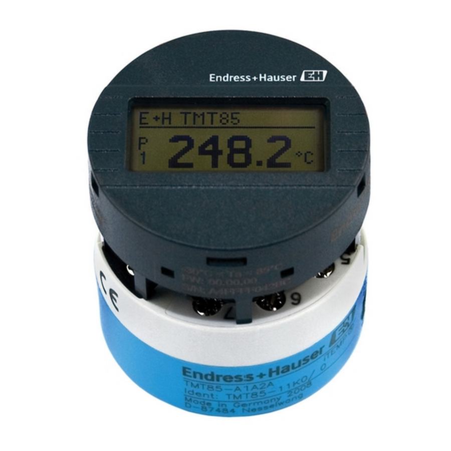
- Page 2 TMT85 Order code: XXXXX-XXXXXX Ser. no.: XXXXXXXXXXXX Ext. ord. cd.: XXX.XXXX.XX Serial number www.endress.com/deviceviewer Endress+Hauser Operations App A0023555 Endress+Hauser...
-
Page 3: Table Of Contents
TMT85 Table of contents Table of contents About this document ............. . 3 Safety Instructions (XA) . -
Page 4: Symbols Used
Basic safety instructions iTEMP TMT85 Symbols used 1.2.1 Safety symbols DANGER This symbol alerts you to a dangerous situation. Failure to avoid this situation will result in serious or fatal injury. WARNING This symbol alerts you to a dangerous situation. Failure to avoid this situation can result in serious or fatal injury. -
Page 5: Intended Use
TMT85 Basic safety instructions The operating personnel must fulfill the following requirements: ‣ Operating personnel are instructed and authorized according to the requirements of the task by the facility' s owner-operator ‣ Follow the instructions in this manual Intended use... -
Page 6: Incoming Acceptance And Product Identification
(www.endress.com/deviceviewer): All data relating to the device and an overview of the Technical Documentation supplied with the device are displayed. • Enter the serial number on the nameplate into the Endress+Hauser Operations App or scan the 2-D matrix code (QR code) on the nameplate with the Endress+Hauser Operations App: all the information about the device and the technical documentation pertaining to the device is displayed. -
Page 7: Scope Of Delivery
Approval in hazardous area with number of the relevant Ex documentation (XA...) Approvals with symbols Order code and manufacturer ID 3.2.2 Name and address of manufacturer Name of manufacturer: Endress+Hauser Wetzer GmbH + Co. KG Address of manufacturer: Obere Wank 1, D-87484 Nesselwang or www.endress.com Address of manufacturing plant: See nameplate... -
Page 8: Installation
Installation iTEMP TMT85 • Certified in accordance with FOUNDATION Fieldbus specification • FOUNDATION Fieldbus • Interoperability Test Kit (ITK), (device certification number available on request): The device can also be operated with certified devices of other manufacturers • Physical Layer Conformance Test of the Fieldbus FOUNDATION... - Page 9 TMT85 Installation 4.2.1 Mounting the head transmitter Item B Item A . 7 2 i n ) Item C . 7 2 i n ) A0039675-EN 2 Head transmitter mounting (three versions) Procedure for mounting in a terminal head, Item A: Open the terminal head cover (8) on the terminal head.
- Page 10 Installation iTEMP TMT85 21 mm (0.83 in) . 7 2 i n ) 6.5 mm (0.25 in) . 5 1 i n ) A0024604 3 Dimensions of angle bracket for wall mount (complete wall mounting set available as accessory) Procedure for mounting in a field housing, Item B: Open the cover (1) of the field housing (4).
- Page 11 TMT85 Installation Mounting typical of North America A0008520 4 Head transmitter mounting Thermometer design with thermocouples or RTD sensors and head transmitter: Fit the thermowell (1) on the process pipe or the container wall. Secure the thermowell according to the instructions before the process pressure is applied.
-
Page 12: Post-Installation Check
When connecting Ex-certified devices, please take special note of the instructions and connection schematics in the Ex-specific supplement to these Operating Instructions. Please contact Endress+Hauser' s representative if you have any questions. ‣ Do not occupy the display connection. Connecting other devices can destroy the electronics. -
Page 13: Connecting The Measuring Device
TMT85 Electrical connection Connecting the measuring device Terminal assignment Sensor input 2 Bus connection Sensor input 1 RTD, Ω: 3- and 2-wire RTD, Ω: 4-, 3- and 2-wire and supply voltage (black) TC, mV (black) TC, mV white white... - Page 14 Electrical connection iTEMP TMT85 Sensor input 1 RTD or resistance transmitter, four-wire Thermocouple (TC), voltage transmitter Connecting to spring terminals A0039468 6 Spring terminal connection, using the example of a head transmitter Item A, solid wire: Strip wire end.
- Page 15 TMT85 Electrical connection Item C, releasing the connection: Press down on the lever opener. Remove the wire from the terminal. Release lever opener. 5.2.2 Fieldbus connection Fieldbus cable specification as per IEC 61158-2 (MBP), see the Operating Instructions for details.
-
Page 16: Post-Connection Check
Electrical connection iTEMP TMT85 Shielding and grounding Optimum electromagnetic compatibility (EMC) of the fieldbus system can only be guaranteed if the system components and, in particular, the lines are shielded and the shield forms as complete a cover as possible. -
Page 17: Operation Options
TMT85 Operation options Device condition and specifications Notes Do the cables used meet the required specifications? Fieldbus cable, Sensor cable, → 13 Do the cables have adequate strain relief? Are the power supply and signal cables connected correctly? →... -
Page 18: Commissioning
Commissioning iTEMP TMT85 6.1.2 Local operation NOTICE ‣ ESD - electrostatic discharge. Protect the terminals from electrostatic discharge. Failure to observe this may result in the destruction or malfunction of parts of the electronics. 1: Connection to head transmitter 2: DIP switches (1 - 64, SW/HW, ADDR and SIM = simulation mode) no function for this head transmitter 3: DIP switch (WRITE LOCK = write protection;... - Page 20 *71498848* 71498848 www.addresses.endress.com...