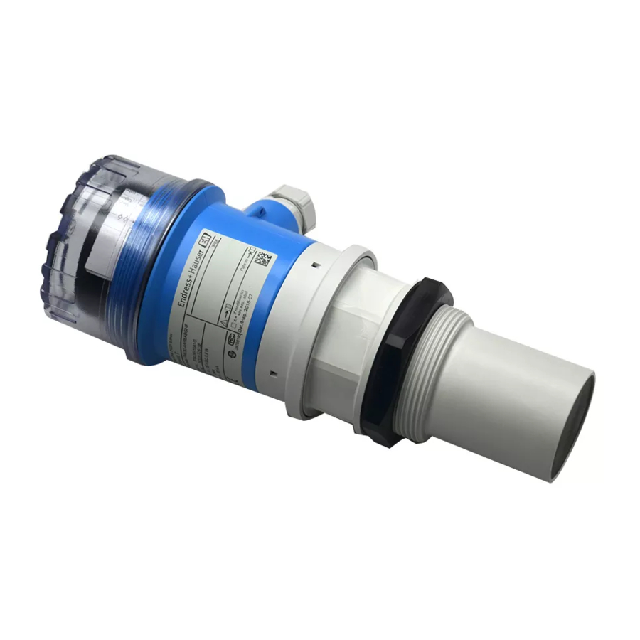
Endress+Hauser Prosonic T FMU30 Brief Operating Instructions
Ultrasonic level measurement
Hide thumbs
Also See for Prosonic T FMU30:
- Operating instructions manual (56 pages) ,
- Technical information (27 pages) ,
- Brief operating instructions (32 pages)
Table of Contents
Advertisement
Quick Links
Brief Operating Instructions
Prosonic T FMU30
Ultrasonic Level Measurement
These are Brief Operating Instructions.
For more detailed information, please refer to the Operating Instructions and the
additional documentation on the CD-ROM provided.
These Brief Operating Instructions are not intended to replace the Operating
Instructions provided in the scope of supply.
The complete device documentation consists of:
• these Brief Operating Instructions
• Approvals and safety certificates
• a CD-ROM with:
– the Operating Instructions
– Technical Information
KA1054F/00/EN/01.10
71106914
Advertisement
Table of Contents

Related Manuals for Endress+Hauser Prosonic T FMU30


Summary of Contents for Endress+Hauser Prosonic T FMU30
- Page 1 Brief Operating Instructions Prosonic T FMU30 Ultrasonic Level Measurement These are Brief Operating Instructions. For more detailed information, please refer to the Operating Instructions and the additional documentation on the CD-ROM provided. These Brief Operating Instructions are not intended to replace the Operating Instructions provided in the scope of supply.
-
Page 2: Table Of Contents
5.8 Envelope curve with device display ............29 Endress+Hauser... -
Page 3: Safety Instructions
Instructions. The installation regulations, connection values and Safety Instructions listed in this Ex document must be observed. The documentation number of the related Safety Instructions is also indicated. Return Follow the instructions on returning the device as outlined in the Operating Instructions on the CD-ROM provided. Endress+Hauser... -
Page 4: Safety Icons
Pack the measuring instrument so that is protected against impacts for storage and transport. The original packing material provides the optimum protection for this. The permissible storage temperature is -40 °C to +80 °C (-40 °F to +176 °F). Endress+Hauser... -
Page 5: Installation
A: Installation with counter nut (1: counter nut (PC) supplied for G1½ and G2 instruments) B: Installation with sleeve (1: sealing ring (EPDM) supplied) C: Installation with installation bracket D: Installation with screw in flange 1: screw in flange 2: sealing ring (EPDM) supplied 3: sensor 4: nozzle Endress+Hauser... -
Page 6: Installation Conditions
• Never install two ultrasonic measuring devices in a tank, as the two signals may affect each other. • To estimate the detection range, use the 3 dB emitting angle α. α Sensor 1½" 11° 5 m (16 ft) 0.48 m (1.6 ft) 2" 11° 8 m (26 ft) 0.77 m (2.5 ft) Endress+Hauser... - Page 7 • Align the sensor membrane parallel to the water surface. • Keep to the installation distance of the channel or weir. Example: Khafagi-Venturi flume 1 x b L00-FMU30xxx-17-00-00-xx-003 A: Khafagi-Venturi flume; B: inflow; C: outflow; E: empty calibration; V: direction of flow Endress+Hauser...
-
Page 8: Measuring Range
The interior of the nozzle must be smooth and may not contain any edges or welded joints. In particular, there should be no burr on the inside of the tank side nozzle end. Note the specified limits for nozzle diameter and length. To minimise disturbing factors, we recommend an angled socket edge (ideally 45°). Endress+Hauser... - Page 9 Blocking distance [m (ft)] 0.25 (0.8) 0.35 (1.1) Max. range [m(ft)] in liquids 5 (16) 8 (26) Max. range [m (ft)] 2 (6.6) 3.5 (11) in solids " Caution! If the blocking distance is undershot, it may cause device malfunction. Endress+Hauser...
- Page 10 The sensor range is dependent on the measuring conditions. Refer to Technical Information TI 440F/00/EN for an estimation. The maximum range is shown in the above diagram (valid for good conditions). Sensor maximum range 1½" 5 m (16 ft) 2" 8 m (26 ft) Endress+Hauser...
-
Page 11: Installation Hint
• If available: Are the measuring point number and labelling correct (visual inspection)? • Is the measuring device sufficiently protected against precipitation and direct sunlight? • Are the cable glands tightened correctly? • After aligning the housing, check the process seal at the nozzle or flange. Endress+Hauser... -
Page 12: Wiring
Installation cable screen to the grounding terminal (5) within the terminal compartment. Make connection according to terminal assignment, → ä 13, "Terminal assignment". Tighten cable gland (4). Insert display (2) if fitted. Screw on housing cover (1). Switch on power supply. L00-FMU30KAx-04-00-00-xx-008 Endress+Hauser... -
Page 13: Terminal Assignment
4...20 mA plant ground L- L+ L00-FMU30xxx-04-00-00-en-015 Supply voltage The following values are the voltages across the terminals directly at the instrument: Current Terminal voltage Terminal voltage minimum consumption maximum 4 mA 14 V 35 V 20 mA 35 V Endress+Hauser... -
Page 14: Potential Matching
After wiring the device, carry out the following checks: • Are the terminals correctly assigned? • Is the cable gland tight? • Is the housing cover fully screwed on? • If power supply available: Does a display appear on the display module? Endress+Hauser... -
Page 15: Operation
4.1.1 Identifying the functions For simple orientation within the function menus, for each function a position is shown on the display. Function Function group L00-FMU4xxxx-07-00-00-en-001 The first two digits identify the function group: • basic setup • safety settings • temperature Endress+Hauser... -
Page 16: Display And Operating Elements
The LCD module for display and operation is located beneath the housing cover. The measured value is legible through the transparent cover. Open the cover to operate the device. FEU31 4...20mA Display L00-FMU30xxx-07-05-xx-xx-000 1: Display symbol; 2: Function keys; 3: Display (rotatable); 4: Plug-in module Endress+Hauser... - Page 17 L00-FMU3xxxx-07-00-00-en-002 In the measured value display, the bargraph corresponds to the output.The bargraph is segmented in 10 bars. Each completely filled bar represents a change of 10% of the adjusted span. Endress+Hauser...
- Page 18 The following table describes the symbols that appear on the liquid crystal display: Sybmol Meaning ALARM_SYMBOL This alarm symbol appears when the instrument is in an alarm state. If the symbol flashes, this indicates a warning. LOCK_SYMBOL This lock symbol appears when the instrument is locked,i.e. if no input is possible. Endress+Hauser...
- Page 19 Contrast settings of the LCD Hardware lock / unlock After a hardware lock, an operation of the instrument via display or communication is not possible! The hardware can only be unlocked via the display. An unlock parameter must be entered to do so. Endress+Hauser...
-
Page 20: Commissioning
Select the basic unit (this message appears the first time the instrument is switched on) ⇓ The current measured value is displayed ⇓ After E is pressed, you reach the group selection. This selection enables you to perform the basic setup Endress+Hauser... -
Page 21: Overview Basic Setup
This function displays the current measured value in the selected unit (see "customer unit" (042) function). The number of digits after decimal point can be selected in the "no.of decimals" (095) funtion. 5.4.2 Function group "basic setup" (00) ⇒ Endress+Hauser... -
Page 22: Measuring Point Settings
In this function, select one of the following options: Selection: • dome ceiling (→ A) • horizontal cyl. (→ B) • bypass (→ C) • stilling well (ultrasonic guide pipe) (→ C) • no ceiling (→ D) • sphere (→ E) • flat ceiling (→ F) L00-FMU4xxxx-14-00-06-de-001 Endress+Hauser... - Page 23 5.5.3 Function "process cond." (004) ⇒ This function is used to select the process conditions: Selection: • standard • calm surface • turb. surface • add. agitator • fast change • standard solid • solid dusty • conveyor belt • Test: no filter Endress+Hauser...
- Page 24 L00-FMU30xxx-14-00-00-xx-006 L00-FMU30xxx-14-00-00-xx-003 L00-FMU30xxx-14-00-00-xx-004 solid dusty conveyor belt Test: no filter Dusty bulk solids Bulk solids with rapid level change All the filters can be switched off for purposes of service and diagnosis. L00-FMU30xxx-14-00-00-xx-005 L00-FMU30xxx-14-00-00-xx-007 Endress+Hauser...
-
Page 25: Empty And Full Calibration
5.6.2 Function "blocking distance" (059) ⇒ In this function the blocking distance (BD) of the sensor is displayed. " Caution! When entering the full calibration (span), please take into account, that the maximum level may not project into the blocking distance (BD). Endress+Hauser... -
Page 26: Interference Echo Suppression (Tank Mapping)
This function triggers the mapping of interference echoes. To do so, the measured distance must be compared with the actual distance to the product surface. The following options are available for selection: Selection: • distance = ok • dist. too small • dist. too big • dist. unknown • manual Endress+Hauser... - Page 27 "process cond." (004) and the "empty calibr." (005) in the "basic setup" (00) function group. • "dist. unknown" if you do not know the actual distance. This means that the following two functions are skipped. • "manual" if you want to specify the suppression area yourself in the following function. Endress+Hauser...
- Page 28 The following cases can occur: • Distance correct – level correct -> basic setup completed • Distance incorrect – level incorrect -> a further interference echo mapping must be carried out "checkdistance"(051). • Distance correct – level incorrect -> check "emptycalibr."(005). Endress+Hauser...
-
Page 29: Envelope Curve With Device Display
Here you can select which information is shown on the display: • envelope curve • substracted signal • mapping Note! The FAC and the interference echo suppression (map) are explained in BA388F "Prosonic T - Description of Instrument Functions" Endress+Hauser... - Page 30 • cyclic Note! If the envelope curve mode is active on the display, the measured values are updated in a slower cycle time. Thus, it is advisable to leave the envelope curve mode after the measuring point has been optimised. Endress+Hauser...
- Page 31 Prosonic T Commissioning Endress+Hauser...
- Page 32 www.endress.com/worldwide KA1054F/00/EN/01.10 71106914 CCS/FM+SGML 6.0 71106914...