Table of Contents
Advertisement
Model No. WESY86303
Serial No.
Write the serial number in the space
above for future reference.
Serial Number Decal (Under Seat)
QUESTIONS?
As a manufacturer, we are
committed to providing complete
customer satisfaction. If you
have questions, or if there are
missing or damaged parts, we
will guarantee complete satisfac-
tion through direct assistance
from our factory.
TO AVOID UNNECESSARY
DELAYS, PLEASE CALL DIRECT
TO OUR TOLL-FREE CUSTOMER
HOT LINE. The trained techni-
cians on our customer hot line
will provide immediate assis-
tance, free of charge to you.
CUSTOMER HOT LINE:
1-800-999-3756
Mon.–Fri., 6 a.m.–6 p.m. MST
CAUTION
Read all precautions and instruc-
tions in this manual before using
this equipment. Save this manual
for future reference.
USER'S MANUAL
Patent Pending
Visit our website at
www.proform.com
new products, prizes,
fitness tips, and much more!
Visit our website at
www.healthrider.com
new products, prizes,
fitness tips, and much more!
Visit our website at
www.nordictrack.com
new products, prizes,
fitness tips, and much more!
Visit our website at
www.weiderfitness.com
new products, prizes,
fitness tips, and much more!
Advertisement
Table of Contents

Related Manuals for Weider WESY86303


Summary of Contents for Weider WESY86303
- Page 1 Model No. WESY86303 Serial No. Write the serial number in the space above for future reference. Serial Number Decal (Under Seat) QUESTIONS? As a manufacturer, we are committed to providing complete customer satisfaction. If you have questions, or if there are...
-
Page 2: Table Of Contents
Remove the PART IDENTIFICATION CHART and the PART LIST/EXPLODED DRAWING before beginning assembly. WEIDER is a registered trademark of ICON Health & Fitness, Inc. ICON Health & Fitness, Inc. (ICON), warrants this product to be free from defects in workmanship and material, under normal use and service conditions, for a period of ninety (90) days from the date of pur- chase. -
Page 3: Important Precautions
IMPORTANT PRECAUTIONS WARNING: To reduce the risk of serious injury, read the following important precautions before using the training system. 1. It is the responsibility of the owner to ensure that all users of the training system are ade- quately informed of all precautions. 2. -
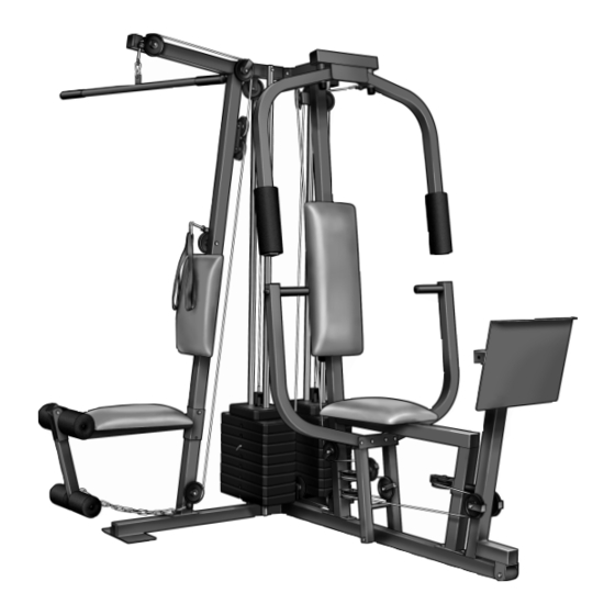
Page 4: Overview & Dimensions
The model number is ® WESY86303. The serial number can be found on a decal attached to the WEIDER cover of this manual). Before reading further, please review the drawing below and familiarize yourself with the parts that are labeled. -
Page 5: Assembly
ASSEMBLY Make Assembly Easier for Yourself! Everything in this manual is designed to ensure that the training system can be assembled successfully by anyone. Before beginning assembly, make sure to read the information on this page; this brief intro- duction will save you much more time than it takes to read it! Assembly Requires Two Persons For your convenience and safety, assemble the... -
Page 6: Frame Assembly
Before you begin this step, make sure that you have read all of the information on page 5. This brief introduction will save you much more time than it takes to read it! Locate and open the parts bags labeled “FRAME ASSEMBLY BAG ONE”... - Page 7 4. Slide the Front Seat Frame (8) onto the indi- cated 5/16” x 2 1/2” Carriage Bolts (49) in the Press Base (13). Hand tighten two 5/16” Nylon Locknuts (40) onto the Carriage Bolts. Attach the other end of the Front Seat Frame (8) to the Leg Press Upright (4) with two 5/16”...
- Page 8 8. Lubricate the insides of the holes in the Top Weights (24) as shown. Slide a Top Weight onto each set of Weight Guides (23). 9. Attach the Top Frame (2) to the Ab Upright (1) with two 5/16” x 2 3/4” Bolts (55), two 5/16” Washers (20), and two 5/16”...
- Page 9 11. Attach the Leg Press Plate (11) to the Adjustment Tube (10) with a 5/16” x 2 1/2” Bolt (39), two 5/16” Washers (20), and a 5/16” Nylon Locknut (40). Be sure that the Leg Press Plate and Adjustment Tube are ori- ented as shown.
- Page 10 15. Attach a Press Arm (7) to one side of the Press Frame (12) with two 5/16” x 2 1/2” Bolts (39) and two 5/16” Nylon Locknuts (40). Attach the other Press Arm (7) to the Press Frame (12) in the same manner. 16.
-
Page 11: Cable Assembly
18. Press a 1 3/4” Square Inner Cap (48) into the lower end of the Left Fly Arm (6). Wet the lower end of the Left Fly Arm with soapy water. Slide a 10” Pad (22) onto the Left Arm. Repeat this step with the Right Fly Arm (5). - Page 12 21. Wrap the Butterfly Cable (89) around a 3 1/2” Pulley (82) as shown. Attach the Pulley and a Cable Trap (80) to the bracket on the Leg Press Upright (4) with a 3/8” x 2” Bolt (50) and a 3/8” Nylon Locknut (42). The Cable Trap must be oriented as shown and be positioned to hold the Cable in the groove of the Pulley.
- Page 13 25. Identify the Rear Cable (87)—this is the shortest Cable. Slide one end of the Rear Cable onto the 5/16” x 3” Bolt (92). Thread another 5/16” Nylon Jam Nut (91) onto the Bolt, but do not fully tighten it. Leave enough room between the two Jam Nuts for the Cable to pivot.
- Page 14 29. Identify the Press Cable (88)—this is the longest Cable. Attach the end of the Press Cable (88) to the Large “U” Bracket (84) with a 1/4” Nylon Locknut (44) and a 1/4” Washer (37). Do not completely tighten the Nylon Locknut.
- Page 15 32. Route the Press Cable (88) over the indicated 3 1/2” Pulley (82) attached to the Pulley Plates (31). The Cable must be routed from the direction shown. Refer to the inset draw- ing. Be sure that the Cable is between the Cable Trap (80) and the Pulley, and that the Cable Trap is positioned to hold the Cable in place.
- Page 16 36. Route the Press Cable (88) over the indicated 3 1/2” Pulley (82) attached to the Press Frame (12). Be sure that the Cable Trap (80) is turned to hold the Cable in place and that the Cable is between the Pulley and the crossbar on the Press Frame.
- Page 17 40. Note: The 3 1/2” Pulley (82) used in this step was attached in step 38. It is shown removed for easier part identification. Route the Press Cable (88) around the 3 1/2” Pulley (82). Be sure that the Cable Trap (80) is turned to hold the Cable in place and that the Cable is routed as shown.
- Page 18 44. Locate the remaining preassembled pair of Pulley Plates (31) and 3 1/2” Pulleys (82). Route the High Cable (85) under the indicated 3 1/2” Pulley (82). The end of the Pulley Plates (31) with two holes should be down- ward.
- Page 19 48. Wrap the Low Cable (86) around a 3 1/2” Pulley (82). Attach the Pulley and a Cable Trap (80) to the Ab Upright (1) with the 3/8” x 3 3/4” Bolt (76) and a 3/8” Nylon Locknut (42). Be sure that the Cable Trap is in the indi- cated position.
-
Page 20: Seat Assembly
51. Locate and open the parts bag labeled “SEAT ASSEMBLY.” Attach the Small Backrest (18) to the Ab Upright (1) with two 1/4” x 2 1/2” Machine Screws (64) and two 1/4” Washers (37). 52. Press a 1 1/2” Square Inner Cap (57) into the Rear Seat Frame (16). - Page 21 55. Press two 3/4” Round Inner Caps (78) into each Pad Tube (28). Insert a Pad Tube (28) into the Rear Seat Frame (16). Slide a Foam Pad (29) onto each end of the Pad Tube. Insert the other Pad Tube (28) into the Leg Lever (15).
-
Page 22: How To Use The Training System
CHANGING THE WEIGHT SETTING The WEIDER 8630 features two weight stacks. The one weight stack is connected to the ab, upper, and lower pulley stations. The other weight stack is con- nected to the fly and press arms and the leg press. - Page 23 ATTACHING THE AB STRAP TO THE AB PULLEY STATION Attach the Ab Strap (35) to the Low Cable (86) at the ab pulley station with a Cable Clip (33). ATTACHING AND REMOVING THE SEAT To attach the Seat (17), set the bracket on the Rear Seat Frame (16) onto the pins on the Ab Upright (1).
-
Page 24: Weight Resistance Chart
WEIGHT RESISTANCE CHART This chart shows the approximate weight resistance at each weight station. “Top” refers to the 6.5 lb. top weight. The other numbers refer to the 12.5 lb. weight plates. The butterfly arm resistance listed is the resistance for each butterfly arm. -
Page 25: Trouble-Shooting And Maintenance
TROUBLE-SHOOTING AND MAINTENANCE Inspect and tighten all parts each time you use the training system. Replace any worn parts immediately. The training system can be cleaned using a damp cloth and mild non-abrasive detergent. Do not use solvents. TIGHTENING THE CABLES Woven cable, the type of cable used on the training system, can stretch slightly when it is first used. -
Page 26: Cable Diagrams
Cables have been assembled correctly. The starting and ending points of each Cable have been labeled. The numbers show the proper route for each Cable. IMPORTANT: If the Cables have not been cor- rectly routed, the WEIDER 8630 will not function properly and damage may occur. Press Cable (88) Low Cable (86) Ab Pulley—1... - Page 27 High Cable (85) Rear Cable (87) 1—Top Frame High Pulley—1 4—Weight Stack Weight Stack—5...
- Page 28 1" x 7/8" Plastikbucshe (54) 1" Innenkapp[e (98) 1" Runde Innenkappe (70) 1 1/8" x 2 1/2" Plastikbucshe (47) 1 1/2" Quadratische Innenkappe (57) 1/2" x 3/4" Abstandsstück (69) 1" Runde Außenkappe (46) 3/4" Runde Innenkappe (78) 1 3/4" Quadratische Innenkappe (48) 2"...
- Page 29 1/4" Unterlegscheibe (37) 5/16" x 1" Bolzen (51) 5/16" Unterlegscheibe (20) 5/16" x 1 3/4" Bolzen (68) 1" Spannringe (45) 3/8" x 2" Bolzen (50) 3/8" Unterlegscheibe (38) 5/16" x 2 1/4" Bolzen (62) 1/4" Nylonvershchlussmutter(44) 5/16" x 2 1/2" Bolzen (39) 5/16"...
- Page 30 1/4" x 2" Maschinenschraube (63) Kabelklammer (33) 1/4" x 2" Schraubenbolzen (61) 1/4" x 2 1/2" Maschinenschraube (64) 1/4" x 2 1/2" Schraubenbolzen (60) 5/16" x 2 1/2" Schraubenbolzen (49) 5/16" x 2 3/4" Schraubenbolzen (77) 5/16" x 2" Augenbolzen (79) 3/8"...
- Page 31 PART LIST—Model No. WESY86303 Key No. Qty. Description Ab Upright Top Frame Butterfly Frame Leg Press Upright Right Fly Arm Left Fly Arm Press Arm Front Seat Frame Leg Press Arm Adjustment Tube Leg Press Plate Press Frame Press Base...
- Page 32 REMOVE THIS PART IDENTIFICATION REMOVE THIS PART IDENTIFICATION CHART FROM THE MANUAL! CHART FROM THE MANUAL This chart is provided to help you identify the small parts used in assembly. Important: Some parts may have been pre-assembled for shipping purposes; if you cannot find a part in the parts bags, check to see if it has been pre-assembled.
- Page 33 REMOVE THIS PART LIST/EXPLODED REMOVE THIS PART LIST/EXPLODED DRAWING FROM THE MANUAL. SAVE DRAWING FROM THE MANUAL! THE PART LIST/EXPLODED DRAWING FOR FUTURE REFERENCE.
-
Page 36: Ordering Replacement Parts
Friday, 6 a.m. until 6 p.m. Mountain Time (excluding holidays). To help us assist you, please be pre- pared to give the following information: 1. The MODEL NUMBER of the product (WESY86303) 2. The NAME of the product (WEIDER ®...