Weider 8630 User Manual
Canadian english manual
Hide thumbs
Also See for 8630:
- Manuel de l'utilisateur (34 pages) ,
- User manual (36 pages) ,
- User manual (33 pages)
Table of Contents
Advertisement
Model No. WESY8630C.5
Serial No.
Write the serial number in the space
above for future reference.
Serial Number Decal (Under Seat)
QUESTIONS?
As a manufacturer, we are com-
mitted to providing complete
customer satisfaction. If you
have questions, or if parts are
damaged or missing, PLEASE
CONTACT OUR CUSTOMER
SERVICE DEPARTMENT
DIRECTLY.
1-888-936-4266
CALL TOLL-FREE:
Mon.–Fri., 8:00 until 17:00 EST
(excluding holidays)
OR E-MAIL US:
customerservice@iconcanada.ca
CAUTION
Read all precautions and instruc-
tions in this manual before using
this equipment. Save this manual
for future reference.
USER'S MANUAL
Visit our website at
www.proform.com
Visit our website at
www.healthrider.com
Visit our website at
www.nordictrack.com
Visit our website at
www.weiderfitness.com
Visit our website at
Advertisement
Table of Contents

Related Manuals for Weider 8630


Summary of Contents for Weider 8630
- Page 1 Model No. WESY8630C.5 Serial No. Write the serial number in the space above for future reference. USER'S MANUAL Serial Number Decal (Under Seat) QUESTIONS? As a manufacturer, we are com- mitted to providing complete customer satisfaction. If you have questions, or if parts are damaged or missing, PLEASE CONTACT OUR CUSTOMER SERVICE DEPARTMENT...
-
Page 2: Table Of Contents
Note: A PART IDENTIFICATION CHART and a PART LIST/EXPLODED DRAWING are attached in the center of this manual. Remove the PART IDENTIFICATION CHART and the PART LIST/EXPLODED DRAWING before beginning assembly. WEIDER is a registered trademark of ICON IP, Inc. -
Page 3: Important Precautions
IMPORTANT PRECAUTIONS WARNING : To reduce the risk of serious injury, read the following important precautions before using the weight system. 1. Read all instructions in this manual and in 12. Never release the press arm, butterfly arms, the accompanying literature before using the leg lever, press plate, lat bar, ab strap, or weight system. -
Page 4: Before You Begin
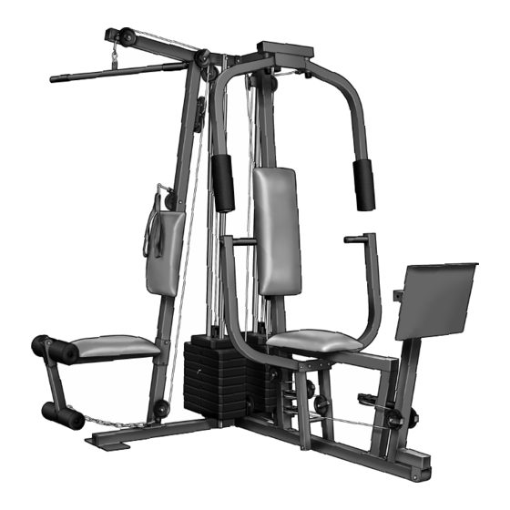
BEFORE YOU BEGIN Thank you for selecting the versatile WEIDER 8630 reading this manual, see the front cover of this manu- ® weight system. The weight system offers a selection of al. To help us assist you, please note the product weight stations designed to develop every major mus- model number and serial number before calling. -
Page 5: Assembly
ASSEMBLY Make sure you have the following tools: Make Assembly Easier for Yourself • Two (2) adjustable wrenches Everything in this manual is designed to ensure that the weight system can be assem- • One (1) standard screwdriver bled successfully by anyone. Before begin- •... -
Page 6: Frame Assembly
Frame Assembly Before beginning assembly, make sure you understand the information in the box on page 5. Refer to the PART IDENTIFICATION CHART in the center of this manual for help identifying small parts. Locate and open the parts bags labeled “FRAME ASSEMBLY.”... - Page 7 4. Slide the Front Seat Frame (8) onto the indicated M8 x 63mm Carriage Bolts (49) in the Press Base (13). Hand tighten two M8 Nylon Locknuts (40) onto the Carriage Bolts. Do not tighten the Locknuts yet. Attach the other end of the Front Seat Frame (8) to the Leg Press Upright (4) with two M8 x 67mm Bolts (55), two M8 Washers (20), and two M8 Nylon Locknuts (40).
- Page 8 8. Lubricate the insides of the indicated holes in the Top Weights (24) with the included grease. Slide a Top Weight onto each set of Weight Guides (23). Lubricate Lubricate 9. Attach the Top Frame (2) to the Ab Upright (1) with two M8 x 67mm Bolts (55), two M8 Washers (20), and two M8 Nylon Locknuts (40).
- Page 9 ARM ASSEMBLY 11. Locate and open the parts bag labeled “ARM ASSEMBLY.” Attach the Leg Press Plate (11) to the Adjustment Tube (10) with an M8 x 60mm Bolt (62), two M8 Washers (20), and an M8 Nylon Locknut (40). Make sure that the Leg Press Plate and Obtuse Adjustment Tube are oriented as shown.
- Page 10 15. Attach a Press Arm (7) to one side of the Press Frame (12) with two M8 x 63mm Bolts (39) and two M8 Nylon Locknuts (40). Attach the other Press Arm (7) to the Press Frame (12) in the same manner. 16.
-
Page 11: Cable Assembly
17. Wet the lower end of the Left Fly Arm (6) with soapy water. Slide a Large Pad (22) onto the Left Fly Arm. Repeat this step with the Right Fly Arm (5). CABLE ASSEMBLY 18. Locate and open the parts bags labeled “CABLE ASSEMBLY,”... - Page 12 20. Wrap the Butterfly Cable (89) around a 90mm Pulley (82) as shown. Attach the Pulley and a Cable Trap (80) to the bracket on the Leg Press Upright (4) with an M10 x 48mm Bolt (50) and an M10 Nylon Locknut (42). The Cable Trap must be oriented to hold the Cable in the groove of the Pulley.
- Page 13 24. Identify the Rear Cable (87)—this is the short- est Cable. Remove the M8 x 69mm Shoulder Bolt (43) from the Top Frame (2). Loosen the indi- cated M8 Nylon Locknut (40). Loosen–40 Attach the Rear Cable to the Top Frame with the M8 x 69mm Shoulder Bolt (43) and an M8 Nylon Locknut (40).
- Page 14 28. Identify the Press Cable (88)—this is the longest Cable. Attach the end of the Press Cable to the Large “U”-bracket (84) with an M8 Nylon Locknut (40) and an M8 Washer (20). Do not completely tighten the Locknut. It should be threaded onto the end of the Cable so that two threads are showing above the Locknut, as shown in the inset drawing.
- Page 15 31. Route the Press Cable (88) over a 90mm Pulley (82). Attach the Pulley and a Cable Trap (80) to the lower hole in the Pulley Plates (31) with an M10 x 48mm Bolt (50) and the M10 Nylon Locknut (42). The Cable must be routed from the direction shown.
- Page 16 35. Route the Press Cable (88) over a 90mm Pulley (82). Attach the Pulley and a Cable Trap (80) to the indicated hole in the Press Frame (12) with an M10 x 82mm Bolt (66), an M10 Washer (38), and an M10 Nylon Locknut (42). 42 80 36.
- Page 17 39. Note: The 90mm Pulley (82) used in this step was attached in step 38. It is shown removed for easier part identification. Route the Press Cable (88) around the 90mm Pulley (82). Make sure that the Cable Trap (80) is turned to hold the Cable in place and that the Cable is routed as shown.
- Page 18 43. Route the High Cable (85) under a 90mm Pulley (82). Attach the Pulley and a Cable Trap (80) to the single hole end of the Pulley Plates (31) with an M10 x 48mm Bolt (50) and the M10 Nylon Locknut (42).
- Page 19 47. Wrap the Low Cable (86) around a 90mm Pulley (82). Attach the Pulley and a Cable Trap (80) to the Ab Upright (1) with the M10 x 92mm Bolt (76) and an M10 Nylon Locknut (42). Make sure that the Cable Trap is in the indicated position.
- Page 20 SEAT ASSEMBLY 50. Locate and open the parts bag labeled “SEAT ASSEMBLY.” Attach the Small Backrest (18) to the Ab Upright (1) with two M6 x 63mm Machine Screws (64) and two M6 Washers (37). 51. Insert an M6 x 52mm Carriage Bolt (61) through the center hole in a Seat Plate (41).
-
Page 21: Adjustments
54. Insert a Pad Tube (28) into the Rear Seat Frame (16). Slide two Foam Pads (29) onto the ends of the Pad Tube. Insert the other Pad Tube (28) into the Leg Lever (15). Slide two Foam Pads (29) onto the ends of the Pad Tube. -
Page 22: Adjustments
ADJUSTMENTS The instructions below describe how each part of the weight system can be adjusted. Refer to the exercise guide accompanying this manual to see how the weight system should be set up for each exercise. IMPOR- TANT: When attaching the lat bar or nylon strap, make sure that the attachments are in the correct start- ing position for the exercise to be performed. - Page 23 ATTACHING THE AB STRAP TO THE AB PULLEY STATION Attach the Ab Strap (35) to the Low Cable (86) at the ab pulley station with a Cable Clip (33). ATTACHING AND REMOVING THE SEAT To attach the Seat (17), set the bracket on the Rear Seat Frame (16) onto the pins on the Ab Upright (1).
-
Page 24: Weight Resistance Chart
WEIGHT RESISTANCE CHART This chart shows the approximate weight resistance at each weight station. “Top” refers to the 6.5 lb. top weight. The other numbers refer to the 12.5 lb. weight plates. The butterfly arm resistance listed is the resistance for each butterfly arm. -
Page 25: Maintenance
MAINTENANCE Inspect and tighten all parts each time the weight system is used. Replace any worn parts immediately. The weight system can be cleaned using a damp cloth and mild non-abrasive detergent. Do not use solvents. TIGHTENING THE CABLES Woven cable, the type of cable used on the weight system, can stretch slightly when it is first used. If there is slack in the cables before resistance is felt, the cables should be tightened. -
Page 26: Cable Diagrams
CABLE DIAGRAMS The cable diagrams on this page and the next page show the proper routing of the High Cable (85), the Low Cable (86), the Rear Cable (87), the Press Cable (88), and the Butterfly Cable (89). Use the diagrams to be sure that the cables have been assembled correctly. - Page 27 High Cable (85) Rear Cable (87) 1—Top Frame High Pulley—1 4—Weight Stack Weight Stack—5...
-
Page 28: Frame Assembly
This chart is provided to help you identify the small parts used in assembly. The number in parenthesis below each part refers to the key number of the part from the PART LIST in the center of this manual. Important: Some parts may have been pre-assembled for shipping purposes. - Page 29 PART IDENTIFICATION CHART—Model No. WESY8630C.5 R0606A M6 x 63mm Machine Screw (64) M6 Nylon Locknut (44) M6 x 63mm Carriage Bolt (60) M8 Nylon Locknut (40) M8 x 63mm Bolt (39) M10 Nylon Locknut (42) M10 x 60mm Bolt (65) M8 x 60mm Bolt (62) M6 Washer (37) M10 x 57mm Bolt (91)
- Page 30 M8 x 67mm Bolt (55) M8 x 63mm Carriage Bolt (49) M8 x 70mm Carriage Bolt (77) M8 x 69mm Shoulder Bolt (43) M10 x 80mm Bolt (71) M10 x 82mm Bolt (66) M10 x 92mm Bolt (76) M10 x 97mm Bolt (95) M10 x 120mm Bolt (74) M8 x 152mm Bolt (67)
- Page 31 REMOVE THIS PART LIST/EXPLODED REMOVE THIS PART LIST/EXPLODED DRAWING FROM THE MANUAL. SAVE DRAWING FROM THE MANUAL! THE PART LIST/EXPLODED DRAWING FOR FUTURE REFERENCE.
- Page 32 PART LIST—Model No. WESY8630C.5 R0606A Key No. Qty. Description Key No. Qty. Description Ab Upright M8 x 22mm Shoulder Bolt Top Frame M10 x 195mm Bolt Butterfly Frame Leg Press Bumper Leg Press Upright 25mm x 22mm Plastic Bushing Right Fly Arm M8 x 67mm Bolt Left Fly Arm 50mm Square Inner Cap...
-
Page 33: Parts Diagram
EXPLODED DRAWING—Model No. WESY8630C.5 R0606A... -
Page 34: Ordering Replacement Parts
• the MODEL NUMBER of the product (WESY8630C.5) • the NAME of the product (WEIDER 8630 weight system) • the SERIAL NUMBER of the product (see the front cover of this manual) • the KEY NUMBER and DESCRIPTION of the part(s) (see the PART LIST and EXPLODED DRAWING attached...