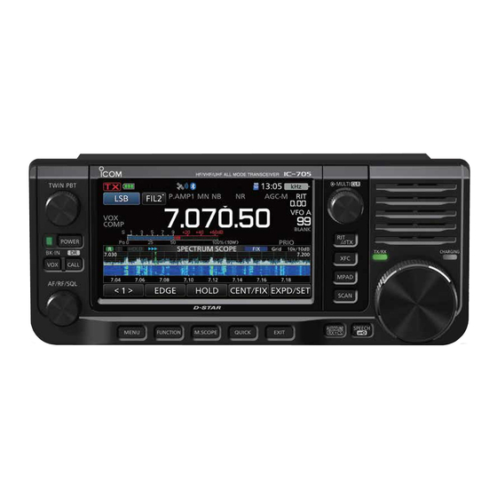
Icom IC-705 Basic Manual
Hf/vhf/uhf all mode transceiver
Hide thumbs
Also See for IC-705:
- Advanced manual (218 pages) ,
- Reference manual (29 pages) ,
- Manual (8 pages)

Related Manuals for Icom IC-705


Summary of Contents for Icom IC-705
- Page 1 BASIC MANUAL HF/VHF/UHF ALL MODE TRANSCEIVER |705 This device complies with part 15 of the FCC Rules. Operation is subject to the condition that this device does not cause harmful interference.
- Page 2 EXPLICIT DEFINITIONS Thank you for choosing this Icom product. This product is designed and built with Icom’ s state of the art technology and craftsmanship. With WORD DEFINITION proper care, this product should provide you Personal death, serious injury RDANGER! with years of trouble-free operation.
- Page 3 • 52.661 MHz • 438.602 MHz Icom is not responsible for the destruction, damage to, or performance of any Icom or non- Icom equipment, if the malfunction is because • Force majeure, including, but not limited to, fires, earthquakes, storms, floods, lightning, or other natural disasters, disturbances, riots, war, or radioactive contamination.
- Page 4 Technology is licensed solely for use within this trademarks owned by the Bluetooth SIG, Inc. and Communications Equipment. any use of such marks by Icom Inc. is under license. The user of this Technology is explicitly Adobe, Acrobat, and Reader are either registered...
- Page 5 ABOUT THE INSTRUCTIONS The Advanced and Basic manuals are 3. Touch [▲] or [▼] to scroll through the items. described in the following manner. LYou can also rotate to scroll through the items. “ ” (Quotation marks): Used to indicate icons, setting items, and screen titles displayed on the screen.
- Page 6 KEYBOARD ENTERING AND EDITING Keyboard types You can select the Full Keyboard or Tenkey pad in “Keyboard Type” on the FUNCTION screen. (p. 8-3) » SET > Function > Keyboard Type LYou can also temporarily switch in the QUICK MENU screen by pushing LYou can select the full keyboard layout in “Full Keyboard Layout”...
- Page 7 0 to 9, A B C D * # TO SELECT Direct input (UR)/(RPT) A to Z, 0 to 9, (space), / [AB]: A to Z, (space) Except for “ICOM BT” Minimum of 8 characters [ab]: a to z, (space) Normally 12 characters [12]: 0 to 9, (space) The maximum number of characters you can enter [!"#]: ! "...
- Page 8 TABLE OF CONTENTS IMPORTANT .............. i Using the VFO mode ....... 3-1 FEATURES ..............i D Selecting VFO A or VFO B ......3-1 EXPLICIT DEFINITIONS ........... i D Equalizing VFO A and VFO B...... 3-1 SUPPLIED ACCESSORIES ........i Selecting the operating band ....
- Page 9 Setting the Speech Compressor ....4-9 Time Set ..........8-18 D Setting before using Bluetooth Set ......... 8-18 the Speech Compressor function ....4-9 WLAN Set ..........8-20 D Using the Speech Compressor function ..4-9 SD Card ..........8-22 Split frequency operation .......
- Page 10 DC power cable. Contact your death. Icom dealer or distributor for advice. R DANGER! NEVER use or charge Icom battery R WARNING! NEVER put the transceiver on an packs with non-Icom transceivers or non-Icom unstable place where the transceiver may suddenly chargers.
- Page 11 Otherwise, the linear amplifier will be damaged. CAUTION: DO NOT use non-Icom microphones. Other microphones have different pin assignments, and may damage the transceiver. DO NOT push PTT unless you actually intend to transmit.
- Page 12 Internal battery gas may cause an explosion. discolored or deformed. If any of these conditions occur, contact your Icom dealer or distributor. R DANGER! NEVER strike or otherwise impact the battery pack. Do not use the battery pack if it has...
- Page 13 - Under a bridge or viaduct of the specified temperature range: 10°C ~ 40°C - In remote forested areas (50°F ~ 104°F). Icom recommends charging the pack - Under bad weather conditions at 25°C (77°F). The pack may heat up or rupture (rainy or cloudy day) if charged out of the specified temperature range.
- Page 14 INITIAL SETUP Selecting a location Attaching the cushions Select a location for the transceiver that allows Attach the cushions, as illustrated below. adequate air circulation, free from extreme heat, cold, or vibration, and other electromagnetic sources. Never place the transceiver in areas such as: •...
- Page 15 INITIAL SETUP Charging the battery pack DBattery icon NOTE: Prior to using the transceiver for the first time, the battery pack must be fully Icon Battery status charged for optimum life and operation. The battery is being charged. LTo charge the battery pack while the transceiver is ON, set the following item to “ON”...
- Page 16 PANEL DESCRIPTION Front panel 7 8 9 10 11 17 18 6 V OLUME/RF GAIN/SQUELCH CONTROL 1 P ASSBAND TUNING CONTROL (p. 4-4) z Rotate to adjust the audio output level. z Push to toggle between “PBT1” and (p. 3-1) “PBT2,”...
- Page 17 PANEL DESCRIPTION Bottom panel Front panel You can attach a third party mounting base 14 T RANSMIT FREQUENCY CHECK KEY using screw holes* on the bottom panel. z In the Split or Duplex mode, holding the key * AMPS hole pattern down enables you to monitor the transmit frequency.
- Page 18 Right side panel Left side panel Mic element 1 S END/ALC JACK [SEND/ALC] (p. 13-2) Connect to control transmit with non-Icom external units or the ALC output jack of a non- Icom linear amplifier. 2 T UNER JACK [TUNER] Accepts the control cable from an external 1 [ PTT] SWITCH antenna tuner with a 3.5 mm (1/8 inch) stereo...
- Page 19 PANEL DESCRIPTION Touch screen display 3 4 5 6 7 8 9 10 11 12 13 14 1 T X STATUS INDICATOR 9 B luetooth ® ICON Displays the transmit status. Displayed when a Bluetooth device is • is displayed while transmitting. connected.
- Page 20 PANEL DESCRIPTION Touch screen display 23 24 26 27 30 V FO/MEMORY ICONS (p. 3-1) 20 M ODE INDICATOR (p. 3-2) Displays “VFO A” or “VFO B” when the VFO Displays the selected operating mode. mode is selected, and displays “MEMO” when 21 I F FILTER INDICATOR (p.
- Page 21 PANEL DESCRIPTION Touch screen display DFUNCTION screen FUNCTION screen list Touch for 1 second to select the function. Function name Touch for 1 second to open its function menu. Status Touch for 1 second to turn ON the Quick Split Lights blue or function.
- Page 22 PANEL DESCRIPTION Touch screen display DMENU screen DMulti-function menus Touch to turn ON or OFF. z Open the Multi-function menu by pushing (Multi-function control). z Open special menus by holding down for 1 second. z While the Multi-function menu is open, touch the desired item and rotate to set the desired value.
- Page 23 PANEL DESCRIPTION Multi-function dial When the Multi-function menu is closed, can be enabled to adjust functions by pushing or touching the item for 1 second on the Multi-function menus. The function is displayed in the upper right corner of the screen. * On the Multi-function menus, touch the item for 1 second to assign the function to Function indicator for...
- Page 24 Selecting the mode Using the VFO mode VFO mode The IC-705 has 2 Variable Frequency Set the desired frequency by rotating Oscillators (VFO), “A” and “B.” Having 2 VFOs is convenient to quickly select 2 frequencies, Memory mode or for split frequency operation (p.
- Page 25 BASIC OPERATION Selecting the operating band Selecting the operating mode Do the following steps to change the operating You can select between the SSB (LSB/USB), band. SSB data (LSB-DATA/USB-DATA), CW, CW reverse, RTTY, RTTY reverse, AM, AM data 1. Touch the MHz digits. (Example: 14) (AM-DATA), FM, FM data (FM-DATA), WFM, and DV modes.
- Page 26 BASIC OPERATION Setting the frequency DUsing the Main Dial DAbout the 1 Hz step Fine Tuning function 1. Select the desired operating band. (p. 3-2) 2. Rotate You can use the minimum tuning step of 1 Hz for • The frequency changes according to the fine tuning in the SSB, CW, and RTTY modes.
- Page 27 BASIC OPERATION Setting the frequency DDirectly entering a frequency You can set the frequency without rotating Entering the Split Frequency Offset by directly entering it using the keypad. 1. Touch the MHz digits. (Example: 14) • Opens the BAND STACKING REGISTER screen.
- Page 28 BASIC OPERATION Setting the frequency D Directly entering a frequency (Continued) DBand Edge Beep Selecting a Memory channel by number You will hear a Band Edge Beep and (with a dotted line) will be displayed when you tune into 1. Select the Memory mode. (p. 3-1) or out of an amateur band’s frequency range.
- Page 29 BASIC OPERATION Setting the frequency Editing a Band Edge Deleting a Band Edge You can edit a band edge entered as a default, You can delete band edges you no longer need. or change the band edge frequencies. 1. Open the “User Band Edge” screen. 1.
- Page 30 BASIC OPERATION Setting the frequency D Entering a Band Edge (Continued) Entering a new Band Edge Inserting a Band Edge You can enter new Band Edge frequencies into You can insert a new Band Edge line, and enter a blank band edge line. new band frequencies, between two entered band edges.
- Page 31 BASIC OPERATION RF gain and SQL level Setting the frequency 1. Push 2. Touch an item to adjust. (Example: RF GAIN) Resetting all band edges to presets The steps below will reset all the band edges to their initial settings. All entered settings will be deleted.
- Page 32 BASIC OPERATION Meter display Adjusting the transmit output power DMeter display selection Before transmitting, monitor your selected You can display one of the 6 different transmit operating frequency to make sure you do not cause parameters (Po, SWR, ALC, COMP, Vd, and Id) interference to other stations on the same frequency.
- Page 33 BASIC OPERATION Setting the maximum transmit Adjusting the microphone gain power 1. Set the operating band and mode to SSB, AM, FM, or DV. (p. 3-2) The maximum transmit power depends on the 2. Push to open the Multi-function menu. power source.
- Page 34 RECEIVING AND TRANSMITTING Preamplifiers Attenuator The preamp amplifies received signals in the Except for 144 and 430 bands receiver front end to improve the signal-to-noise The Attenuator prevents a desired signal from ratio and sensitivity. A preamp is used when becoming distorted when a very strong signal receiving weak signals.
- Page 35 RECEIVING AND TRANSMITTING RIT function Monitor function The Receive Increment Tuning (RIT) function The Monitor function enables you to monitor compensates for differences in frequencies of your transmit audio. Use this function to check other stations. the voice characteristics while adjusting transmit The function shifts your receive frequency up to audio parameters.
- Page 36 RECEIVING AND TRANSMITTING AGC function control SSB, CW, RTTY, and AM modes DSetting the AGC time constant The Automatic Gain Control (AGC) function You can set the preset AGC time constant to the controls receiver gain to produce a constant desired value.
- Page 37 IF frequency to the Digital Twin PBT. slightly above or below the IF center frequency. The IC-705 uses the digital function using the FPGA (Field Programmable Gate Array) filtering method. LEach mode memorizes the PBT setting.
- Page 38 SSB, CW, RTTY, and AM modes Mode IF filter Selectable range (steps) The IC-705 has 3 IF filter passband widths for FIL 1 (3.0 kHz) 50 Hz to 500 Hz (50 Hz)/ each mode, and you can select them on the FIL 2 (2.4 kHz)
- Page 39 RECEIVING AND TRANSMITTING Notch Filter SSB, CW, RTTY, AM, and FM modes DSetting the Manual Notch filter The IC-705 has Auto Notch and Manual Notch When Manual Notch is selected, adjust the functions. filtered frequency. Auto Notch automatically attenuates beat tones, tuning signals, and so on.
- Page 40 RECEIVING AND TRANSMITTING Noise Blanker SSB, CW, RTTY, and AM modes DAdjusting the NB level and time The Noise blanker eliminates pulse-type noise, To deal with various type of noise, you can such as the noise from car ignitions. adjust the attenuation level and blanking depth and width in the NB menu.
- Page 41 RECEIVING AND TRANSMITTING Noise Reduction Setting the transmit filter width The Noise Reduction function reduces random SSB mode noise components and enhances signal audio. The transmit filter width for the SSB and SSB-D modes can be set. WIDE (wide), MID (middle), 1.
- Page 42 RECEIVING AND TRANSMITTING Setting the Speech Compressor SSB mode DUsing the Speech Compressor The Speech Compressor increases the average function RF output power, improving readability at the 1. Touch the Multi-function meter again to receiving station. This function compresses the display the COMP meter.
- Page 43 RECEIVING AND TRANSMITTING Split frequency operation Split frequency operation enables you to There are 2 ways to use Split frequency transmit and receive on different frequencies in operation. the same band. • Use the Quick Split function • Use the receive and transmit frequencies set to VFO A and VFO B.
- Page 44 RECEIVING AND TRANSMITTING Split Lock function Split frequency operation To prevent accidentally changing the receive DUsing the receive and transmit frequency by releasing while rotating frequencies set to VFO A and VFO B , use the Split Lock function. Using both 1.
- Page 45 The IC-705 is capable of operating in the Semi Break-in and Full break-in modes. 1. Select the CW mode.
- Page 46 RECEIVING AND TRANSMITTING Operating CW DAbout the electronic Keyer function You can set the Memory Keyer function settings, paddle polarity settings, and so on of EDIT KEYER MEMORY edit menu the Electronic Keyer. You can edit the Keyer memories M1 to M8. 1.
- Page 47 SCOPE OPERATION Spectrum scope screen The spectrum scope enables you to display the DUsing the Spectrum Scope activity on the selected band, as well as the Display the SPECTRUM SCOPE screen. relative strengths of various signals in that band. » SCOPE The transceiver has two spectrum scope modes, the Center mode and the Fixed mode.
- Page 48 SCOPE OPERATION Spectrum scope screen Center mode DTouch screen operation Displays signals around the operating frequency By touching the FFT scope zone or the waterfall within the selected span. The operating frequency zone in the SPECTRUM SCOPE screen, the is always displayed in the center of the screen. area will be zoomed in.
- Page 49 SCOPE OPERATION Audio scope screen This audio scope enables you to display the DAUDIO SCOPE SET screen received signal’s frequency component on the This screen is used to set the FFT scope FFT scope, and its waveform components on waveform type, color, Waterfall display, and the Oscilloscope.
- Page 50 In that case, use a new one. We recommend you to make a backup of the data onto another device. • Icom will not be responsible for any damage caused by data corruption on a card. Saving data You can save the following data onto the card.
- Page 51 microSD CARD Saving the setting data Unmounting The Memory channels and the transceiver’s Before you remove a card when the transceiver settings can be saved onto a microSD card. is ON, be sure to electrically unmount it, as shown below. 1.
- Page 52 GPS OPERATION Checking your location NOTE: The built-in GPS receiver cannot calculate its position if it cannot receive signals from the GPS satellites. Refer to page xii for You can check your current location. details. LIf you transmit while displaying the GPS POSITION screen, the screen closes.
- Page 53 GPS OPERATION GPS Logger function The GPS Logger function enables you to save the location data from a GPS receiver onto a microSD card as a log. The GPS Logger saves Latitude, Longitude, Altitude, Positioning state, Course, Speed, Date, and Time. If you use this GPS Logger while traveling, you can check your trip history on a mapping software.
- Page 54 SET MODE Set mode description You can use the Set mode to set infrequently TIP: The Set mode is constructed in a tree changed values or function settings. structure. You can go to the next tree level, or go back a level, depending on the selected item.
- Page 55 SET MODE Beep Level Limit (Default: ON) NOTE: The default settings shown below Selects whether or not to limit the volume up to are for the USA transceiver version. The a specified level. default settings may differ, depending on your •...
- Page 56 SET MODE Function » SET > Function Power Save (Default: Auto (Short)) Sets the Power Save function to reduce the NOTE: The Power Save function is disabled when: current drain and conserve battery power. • Using an external power source. When the Power Save function is activated, the •...
- Page 57 LIf an external equipment’s rise time is slower than SPLIT LOCK (Default: OFF) that of the IC-705, a reflected wave is produced, and it may damage the IC-705 or the external Turns the Split Lock function ON or OFF. device. To prevent this, set the appropriate delay...
- Page 58 SET MODE MODE SPEECH (Default: OFF) Function Turns the operating mode announcement ON or OFF. » SET > Function • OFF: The selected operating mode is not announced. RTTY Shift Width (Default: 170) • ON: The selected operating mode is Selects the RTTY shift width.
- Page 59 SET MODE [NOTCH] Switch (SSB) (Default: Auto/Manual) » SET > Function > Remote MIC Key [NOTCH] Switch (AM) (Default: Auto/Manual) (Default: Home CH) Selects the Notch function used in the SSB or (Default: VFO/MEMO) AM mode. [] (Default: UP (VFO: kHz)) •...
- Page 60 SET MODE The assignable key functions Function Description Function Description No function Push to set the frequency to be skipped Temporary while scanning. Push to increase the frequency (in 50 Hz Skip The selected frequencies are temporarily steps*), Memory channel, repeater, or skipped for faster scanning.
- Page 61 SET MODE Auto Reply (Default: OFF) My Station Sets the Automatic Reply function to ON, OFF, Voice, or Position. This function automatically » SET > My Station replies to a call addressed to your own call sign My Call Sign (MY), even if you are away from the transceiver.
- Page 62 SET MODE » SET > DV Set DV Set Digital Monitor (Default: Auto) » SET > DV Set > DV Fast Data Selects a receive mode when is pushed in the DV mode. Fast Data (Default: OFF) • Auto: Receives in the DV mode or the FM Selects whether or not to use the DV Fast Data mode, depending on the received function for data communication in the DV mode.
- Page 63 • The folder name is automatically created, as When an EMR signal is received, the audio [IC-705\RxLog]. will be heard at the programmed level, or the • The file name is automatically created, as shown transceiver’s audio level, whichever is higher.
- Page 64 SET MODE The call log contents are shown below: Contents Example Descriptions TX/RX Transmission and reception Date 1/1/2020 13:51:48 1/1/2020 13:51:48 Date and time the call was started. Frequency 438.010000 438.010000 Operating frequency Operating mode Mode ( USB/USB-D/LSB/LSB-D/CW/CW-R/RTTY/ RTTY-R/AM/AM-D/FM/FM-D/WFM/DV) Your latitude (unit: degrees) My Latitude 34.764667 34.764667...
- Page 65 Barometric (unit: hPa) Records to one decimal place. Humidity Humidity (unit: %) GPS Time Stamp 12:00:00 Time data that the caller station acquires along with the position data Caller is “NMEA”: Records the GPS message GPS Message Osaka City/IC-705 Caller is “D-PRS: Records the D-PRS comment 8-12...
- Page 66 SET MODE IF Output Level (Default: 50%) Connectors Sets the IF output level of the [microUSB] port, when “Output Select” of USB is set to “IF.” » SET > Connectors SP Jack Function (Default: Speaker) » SET > Connectors > WLAN AF/IF Output Selects the audio output from the [SP] jack.
- Page 67 CW Keying signal from the software installed the USB driver, USB (A) and USB (B) are on the PC. Select the same terminal as the named as “IC-705 Serial Port A (CI-V)” and “IC-705 Serial Port B.” terminal set by the software.
- Page 68 SET MODE RX Call Sign Display (Default: Normal) Display In the DV mode, selects whether or not to display the call sign and the message of the » SET > Display caller station when a call is received. LCD Backlight (Default: 50%) •...
- Page 69 SET MODE RX Position Display Timer (Default: 10sec) Scroll Speed (Default: Fast) Sets the RX position data’s time period to Sets the scrolling speed of the message, call display in a dialog. sign, or other text, that are displayed on the •...
- Page 70 SET MODE When you set the system language of the Display transceiver to Japanese, the transceiver has the capability to display both English and Japanese » SET > Display characters. HOWEVER, if you select Japanese, all menu items throughout the transceiver system Display Language (Default: English) will be displayed in only Japanese characters.
- Page 71 SET MODE Time Set Bluetooth Set » SET > Time Set > Date/Time » SET > Bluetooth Set Date Bluetooth (Default: OFF) Sets the date (Year/Month/Day). Turns the Bluetooth function ON or OFF. LThe day of the week is automatically set. Auto Connect (Default: ON) Time...
- Page 72 PTT control. NOTE: DO NOT select “PTT” when the » SET > Bluetooth Set > Headset Set microphone is not connected to the transceiver, > Icom Headset > Custom Key and you use only the Bluetooth headset. [PLAY] (Default: Home CH)
- Page 73 SET MODE » SET > Bluetooth Set > Data Device Set WLAN Set Serialport Function (Default: CI-V (Echo Back OFF)) » SET > WLAN Set Sets the serial port function for the Bluetooth WLAN (Default: OFF) SPP (Serial Port Profile) connection to a data Turns the Wireless LAN function ON or OFF.
- Page 74 Network Radio Name (Default: IC-705) transfers between the IC-705 and the remote Sets the IC-705’s name of up to 16 characters station, when you remotely control the IC-705. that is displayed in the remote control software, when you remotely control the IC-705.
- Page 75 SET MODE » SET > SD Card SD Card Opening Picture » SET > SD Card Selects the picture that is displayed at power ON. LSee the Advanced Manual for details. Load Setting Selects the saved data file to load. SD Card Info Displays the microSD card capacity and the Save Setting...
- Page 76 SET MODE » SET > Others > Reset Others Partial Reset » SET > Others > Information Resets operating settings to their default values (VFO frequency, VFO settings, menu contents) Voltage without clearing the items below: Displays the battery voltage of the attached Li- •...
- Page 77 4. To close the DATE/TIME screen, push several times. NOTE: The backup battery for the internal clock The IC-705 has a rechargeable Lithium battery to backup the internal clock. If you connect the transceiver to a power source, the battery is charged and it keeps the correct clock setting.
- Page 78 MAINTENANCE Cleaning Resetting DO NOT use harsh solvents Occasionally, erroneous information may such as benzine or alcohol when be displayed. This may be caused by static cleaning, because they will damage electricity or by other factors. the transceiver surfaces. If this problem occurs, turn OFF the transceiver. After waiting a few seconds, turn ON the If the transceiver becomes dusty or transceiver again.
- Page 79 MAINTENANCE Resetting Partial reset DAll reset 1. Open the RESET screen. 1. Open the RESET screen. » SET > Others > Reset » SET > Others > Reset 2. Touch “Partial Reset.” 2. Touch “All Reset.” 3. Touch [YES]. 3. Touch [NEXT]. LAfter resetting, the default VFO mode screen 4.
- Page 80 If you are unable to locate the cause of a problem or solve it through the use of this chart, contact your nearest Icom Dealer or Service Center. LSee the Advanced Manual for the problems when communicating through a repeater.
- Page 81 MAINTENANCE Troubleshooting Problem Possible Cause Solution REF. No power output or the output The microphone is bad, or the Test the microphone and check p. 13-3 power is too low. [MIC] jack is shorted or defective. the [MIC] jack. The antenna SWR is more than Adjust the antenna for an SWR of 3:1.
- Page 82 “– No File –” is displayed on The firmware file is in an incorrect Copy the firmware file into the the FIRMWARE UPDATE folder. IC-705 folder. screen. The firmware file name is Download the firmware file again. different. The microSD card is not Format the microSD card.
- Page 83 0.5 A (typical) 18.068000 ~ 18.168000 Transmit 21.000000 ~ 21.450000 Maximum power (10 W) 3.0 A 24.890000 ~ 24.990000 Using specified Icom’s battery pack (7.4 V DC) 28.000000 ~ 29.700000 Receive 50.000000 ~ 54.000000 Standby 0.5 A (typical) 144.000000 ~ 148.000000 Maximum audio 0.8 A (typical)
- Page 84 SPECIFICATIONS DReceiver • Selectivity (Filter: SHARP): SSB (BW=2.4 kHz) More than 2.4 kHz/–6 dB • Receive system: Less than 3.4 kHz/–40 dB 0.03 ~ 24.999999 MHz CW (BW=500 Hz) More than 500 Hz/–6 dB RF Direct Sampling Less than 700 Hz/–40 dB 25 ~ 199.999999 MHz, 400 ~ 470 MHz RTTY (BW=500 Hz) More than 500 Hz/–6 dB Down Conversion IF Sampling...
- Page 85 5 devices L Either headsets or data devices are maximum 4 devices, and the combination is 5 devices in total. • Device Name: ICOM BT(IC-705) (default value) • Passkey: 0000 (four zeros) LAll stated specifications are typical and subject to change without notice or obligation.
- Page 86 Before using, read each manual and guide, and use it according to the instructions. LTo add or expand a function, or to improve the performance, the software version may be upgraded. Before you update your software version, see the instructions and cautions described on the Icom website.
- Page 87 LYou cannot connect the optional cigarette lighter • DC 13.8 V (Capacity: At least 5 Amps) cable (CP-22 and CP-23L) to the IC-705’s • A power supply with an over current protective [DC 13.8 V] jack. line, and low voltage fluctuation or ripple.
- Page 88 2 SEND LThe external keypad shown below is not supplied To control an external device such as a non- by Icom. Icom linear amplifier, the terminal goes low when the transceiver transmits. External Keypad 3.5 mm (1/8 inch) 1 ALC 1.5 kΩ...
- Page 89 LYou can change the signal output type and output (8 Ω load, 10% distortion) level. LYou can download the USB driver and installation When using the amplifier for a headset: guide from the Icom website. • Output impedance: 10 Ω https://www.icomjapan.com/support/ • Output level: More than 5 mW (16 Ω...
- Page 90 INSTALLATION NOTES Vertical clearance by EIRP output For amateur base station installations it is recommended that the forward clearance in front of 1 Watts 2.1 m the antenna array is calculated relative to the EIRP 10 Watts 2.8 m (Effective Isotropic Radiated Power). The clearance 25 Watts 3.4 m height below the antenna array can be determined in 100 Watts...
- Page 91 FCC and IC with this radio. RF exposure limits for “Occupational Use Only”. In addition, your Icom radio complies with the following • DO NOT transmit for more than 50% of the total Standards and Guidelines with regard to RF energy radio use time (“50% duty cycle”).
- Page 92 ABOUT THE LICENSES Information on the open source software being used by fitness for any purpose. The Contributing Authors and this product. Group 42, Inc. assume no liability for direct, indirect, incidental, special, exemplary, or consequential COPYRIGHT NOTICE, DISCLAIMER, and LICENSE: damages, which may result from the use of the PNG If you modify libpng you may insert additional notices Reference Library, even if advised of the possibility of...
- Page 93 FOR A PARTICULAR PURPOSE ARE DISCLAIMED. format, written on top of zlib by Gilles Vollant <info@ IN NO EVENT SHALL COPYRIGHT HOLDERS AND winimage.com>, is available in the contrib/minizip CONTRIBUTORS BE LIABLE FOR ANY DIRECT, directory of zlib. INDIRECT, INCIDENTAL, SPECIAL, EXEMPLARY, Notes for some targets: OR CONSEQUENTIAL DAMAGES (INCLUDING, BUT - For Windows DLL versions, please see win32/...
- Page 94 INDEX 1/4 Tuning function ���������������������������������������������������� 3-3 Microphone gain ������������������������������������������������������ 3-10 Microphone plate ������������������������������������������������������� 1-1 microSD card ������������������������������������������������������������� 6-1 AGC function ������������������������������������������������������������� 4-3 Monitor function ��������������������������������������������������������� 4-2 All reset�������������������������������������������������������������������� 10-2 Multi-function Attenuator ������������������������������������������������������������������ 4-1 Dial ������������������������������������������������������������������������ 2-8 Audio scope ��������������������������������������������������������������� 5-3 Menus �������������������������������������������������������������������...
- Page 95 MEMO...
- Page 96 A7560D-1EX-1 Printed in Japan 1-1-32 Kamiminami, Hirano-ku, Osaka 547-0003, Japan © 2020 Icom Inc. Jul. 2020...