Icom IC-7000 Instruction Manual
Hide thumbs
Also See for IC-7000:
- Instruction manual (166 pages) ,
- Service manual (93 pages) ,
- Manual (34 pages)
Advertisement
Quick Links
Advertisement

Related Manuals for Icom IC-7000


Summary of Contents for Icom IC-7000
- Page 1 INSTRUCTION MANUAL HF/VHF/UHF ALL MODE TRANSCEIVER i7000...
- Page 2 Qty. the IC-7000 your radio of choice, and hope you agree q Hand microphone (HM-151) ......1 with Icom’s philosophy of “technology first.” Many w DC power cable* (OPC-1457) ..... 1 hours of research and development went into the de- or (OPC-1457R) ....
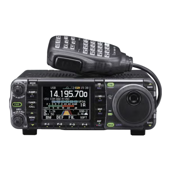
- Page 3 ILLUSTRATIONS Front panel HM-151 ⁄3 ⁄2 SPCH TUNER /LOCK /CALL ⁄1 ⁄0 Mic element MODE GENE F-INP The front panel and HM-151’s panel descriptions are descrived on pages 1 to 4, and on page 9, respectively (see the Chapter 1 ‘PANEL DE- SCRIPTION’...
- Page 4 ■ Front panel ■ Microphone (HM-151) q AF GAIN CONTROL [AF] (inner control; p. 33) z SPCH/LOCK KEY [SPCH/LOCK] (p. 34, 37) w RF GAIN CONTROL/SQUELCH CONTROL x PTT SWITCH [PTT] (p. 37) [RF/SQL] (outer control; p. 35) c UP/DOWN SWITCHES [Y Y ]/[Z Z ] e POWER KEY [PWR] (p.
- Page 5 IC-7000 ONLY. manufacturer’s microphones have different pin assign- NEVER expose the transceiver to rain, snow or any liq- ments, and connection to the IC-7000 may damage the uids. transceiver. AVOID using or placing the transceiver in areas with tem- peratures below –10°C (+14°F) or above +60°C (+140°F).
- Page 6 TABLE OF CONTENTS IMPORTANT …………………………………………i-1 D Differences between VFO and FOREWORD ………………………………………… i-1 memory mode ………………………………… 26 ■ VFO operation …………………………………… 27 EXPLICIT DEFINITIONS …………………………… i-1 D Selecting VFO A/VFO B ……………………… 27 SUPPLIED ACCESSORIES …………………………i-1 ILLUSTRATIONS ……………………………………i-2 D VFO equalization ……………………………… 27 ■...
- Page 7 TABLE OF CONTENTS ■ Noise reduction ………………………………… 79 4 Paddle Polarity ……………………………… 50 D Noise reduction set mode …………………… 79 5 Keyer Type ………………………………… 50 ➥ NR Level …………………………………… 79 6 MIC U/D Keyer (HM-103) ………………… 50 ■ Notch function …………………………………… 80 D Paddle operation from [MIC] connector ……...
- Page 8 TABLE OF CONTENTS ■ Quick set mode ………………………………… 121 D Selecting a memory channel ➥ RF Power (all modes) ……………………… 121 using the memory channel list……………… 103 ➥ MIC Gain (SSB/AM/FM modes)…………… 121 D Setting a memory channel ➥ SSB TBW (WIDE) L (SSB mode) ………… 121 as a select memory …………………………...
- Page 9 TABLE OF CONTENTS 17 Tuner (Auto Start) ………………………… 130 D Codes for memory name contents ………… 147 18 Tuner (PTT start) …………………………… 131 D Split/Duplex frequency setting……………… 147 19 [TUNER] Switch …………………………… 131 D Repeater tone/tone squelch frequency 20 VSEND Select ……………………………… 131 setting …………………………………………...
- Page 10 PANEL DESCRIPTION See the illustration of the Front panel on page i-2. ■ Front panel q AF GAIN CONTROL [AF( • When functioning as squelch control )] (inner control; p. 33) ➥ Rotate to vary the audio output level from the (RF gain is fixed at maximum.) speaker or headphones.
- Page 11 PANEL DESCRIPTION y TWIN PBT (M-ch/RIT) INDICATOR ✔ What is the PBT control? (pgs. 73, 77, 86, 100) PBT electronically narrows the IF passband width to reject ➥ Indicates the status of [PBT/M-ch/RIT] (t) as the interference. This transceiver uses DSP to implement PBT. Twin PBT function or memory channel/RIT con- ➥...
- Page 12 ■ ■ ■ GBR ■ ■ ■ ■ ■ ■ ■ ■ ■ ■ ■ ■ ■ ■ ■ ■ A-6478H-1EX-wa Printed in Japan © 2005–2007 Icom Inc. 1-1-32 Kamiminami, Hirano-ku, Osaka 547-0003, Japan Printed on recycled paper with soy ink.