
Related Manuals for Clarke CS69D


Summary of Contents for Clarke CS69D
- Page 1 BELT & DISC SANDER MODEL NO: CS69D PART NO: 6500421 OPERATION & MAINTENANCE INSTRUCTIONS ORIGINAL INSTRUCTIONS GC0420 - ISS 1...
-
Page 2: Environmental Recycling Policy
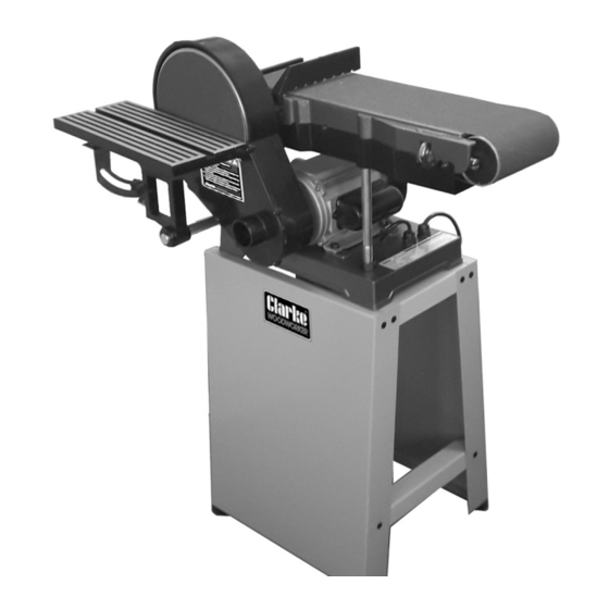
INTRODUCTION Thank you for purchasing this CLARKE Belt and Disc Sander. The CS69D is designed for workshop use and comprises a 9” diameter sanding disc and a 6” wide sanding belt. This machine is designed for sanding WOOD ONLY. DO NOT USE for sanding asbestos or materials containing asbestos, painted surfaces, or materials which produce toxic dust. -
Page 3: Specifications
SPECIFICATIONS Model no CS69D Part no 6500421 Rated Voltage 230V ~ 50Hz Power output 1.5 HP/1.1kW Rated input wattage 1100W Rated input ampere 4.8 A Duty cycle S1 (continuous) IP rating IPX0 Electrical insulation class Class 1 Fuse rating Disc Speed... -
Page 4: Power Tool Safety Warnings
POWER TOOL SAFETY WARNINGS WORK AREA 1. Keep the work area clean and well lit. Cluttered and dark areas invite accidents. 2. Do not operate power tools in explosive atmospheres, such as in the presence of flammable liquids or gases. Power tools create sparks which may ignite the dust or fumes. -
Page 5: Additional Safety Warnings For Sanders
5. Dress properly. Do not wear loose clothing or jewellery. Keep your hair, clothing and gloves away from moving parts. Loose clothes, jewellery or long hair can be caught in moving parts. POWER TOOL USE AND CARE 1. Do not force the power tool. Use the correct accessories for your application. -
Page 6: Electrical Connections
ELECTRICAL CONNECTIONS WARNING: READ THESE ELECTRICAL SAFETY INSTRUCTIONS FULLY BEFORE CONNECTING THE PRODUCT TO THE MAINS SUPPLY. This product is provided with a standard, 230 volt (50Hz), BS 1363 plug, for connection to a standard, domestic electrical supply. Should the plug need changing, make sure that a plug of identical specification is used. -
Page 7: Explanation Of Symbols & Pictograms
EXPLANATION OF SYMBOLS & PICTOGRAMS Read instruction manual before use. Wear safety glasses or goggles when using the tool. Wear ear protection when using this tool. Wear a dust mask. Wear protective gloves. For indoor use only Parts & Service: 020 8988 7400 / E-mail: Parts@clarkeinternational.com or Service@clarkeinternational.com... - Page 8 INVENTORY The CS69D sander is supplied with the following items which will require assembly. • Stand assembly kit, comprising: - 2 x side panels, 2 x short cross members, 2 x long cross members, 4 x rubber feet with flat washers & nuts, 12 x M8 coach bolts /12 x M8 plain washers/12 x M8 nuts.
-
Page 9: Before Use
BEFORE USE ASSEMBLING THE STAND Assemble the stand as shown. The upper and lower beams are secured with the 12 x M8 coachbolts with flat washers & nuts. Add the rubber feet securing them with flat washers & nuts. Do not tighten the nuts until all bolts are in place and the stand is rocked to ensure it is stable and evenly assembled. - Page 10 2. Slide the 5 x 55 mm parallel key into the groove in the shaft and slide driven pulley onto the end of the driven shaft, engaging with the key. 3. Pass the drive belt over both pulleys and slide the motor pulley onto the motor shaft complete with the 5 x 25 mm parallel key.
-
Page 11: Checks Before Use
9. Check that the surface of the face plate is clean and attach the abrasive disc after peeling off the backing material. Take great care to position it centrally. 10. Fit the drive cover using the self- tapping screws. Fit the work stop to the frame using the M8 x 20 bolt and flat washer. - Page 12 CHECKING THE BELT TRACKING The rollers must run parallel, otherwise the belt will be driven off to one side. 1. Plug in to the mains supply and press the GREEN ON button, marked ‘I’ to start the machine. keeping well away from the belt. 2.
- Page 13 3. To ensure the table is at exactly to the sanding disc, position a small engineers set square on the table so that it touches the disc. Slacken off the table angle adjustment knob, shown and adjust accordingly so that the table sits level.
-
Page 14: Method Of Use
METHOD OF USE USING THE DISC 1. Check that the table is approximately 2mm from the sanding disc before switching on. 2. Hold the work firmly as shown and ALWAYS hold the workpiece against the left half of the disc. i.e. that half moving downwards towards the sanding table. - Page 15 USING THE BELT The work stop must be in place when using the belt horizontally. 1. Secure using the bolt and flat washer as shown. 2. Ensure a gap of no more than 2mm exists between the belt and the work stop. 3.
-
Page 16: Dust Extraction
51mm (2”). Connect a suitable hose to a vacuum cleaner via a reducer if required, or dust extraction device (see your CLARKE dealer). NOTE: The user should still wear a face mask to prevent the inhalation of dust particles. -
Page 17: Maintenance
Do not use any abrasive or solvent-based cleaner. A damaged power cable should be replaced by your CLARKE dealer or qualified electrician. The bearings in this sander are sealed for life and require no maintenance. -
Page 18: Fault Finding
EXCESSIVE MOTOR SPARKING OCCURS This indicates worn brushes. This problem is quickly remedied but you should consult your CLARKE dealer for parts and advice. SANDER DOES NOT OPERATE WHEN SWITCHED ON Check to ensure the fuse is sound and replace if necessary. If the fuse is sound or blows repeatedly, consult your CLARKE dealer. - Page 19 Tension the belt by means of the adjsuting bolts shown on page 10. ACCESSORIES Replacement discs and belts are available in packs of 5 from your CLARKE dealer. Please quote the part numbers below.
-
Page 20: Parts Diagram
PARTS DIAGRAM Parts & Service: 020 8988 7400 / E-mail: Parts@clarkeinternational.com or Service@clarkeinternational.com... -
Page 21: Parts List
PARTS LIST No Description No Description Abrasive belt M8 x 10 set screw Bearing cover Abrasive disc Circlip Disc cover Bearing Pointer M8 nut 4mm flat washer Lock washer 4mm lock washer Drum cover M4 x 5 pan head screw M8x10 set screw Lock knob Connecting rod... - Page 22 5mm flat washer M6 nut 5mm lock washer M8 nut M5 hex nut 8mm lock washer Switch 8mm flat washer Self tapping screw Strain relief 1 Switch plate Strain relief 2 M8 x 20 set screw M8 x 20 bolt Base M8 x 10 setscrew Cable clamp plate...
-
Page 23: Declaration Of Conformity
DECLARATION OF CONFORMITY Parts & Service: 020 8988 7400 / E-mail: Parts@clarkeinternational.com or Service@clarkeinternational.com...