
Related Manuals for Clarke CS4-6E


Summary of Contents for Clarke CS4-6E
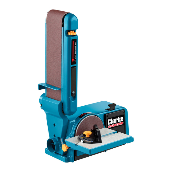
- Page 1 BELT & DISC SANDER MODEL NO: CS4-6E PART NO: 6500413 OPERATION & MAINTENANCE INSTRUCTIONS ORIGINAL INSTRUCTIONS LS0917...
- Page 2 INTRODUCTION Thank you for purchasing this CLARKE product. Before attempting to use this product, please read this manual thoroughly and follow the instructions carefully. In doing so you will ensure the safety of yourself and that of others around you, and you can look forward to your purchase giving you long and satisfactory service.
-
Page 3: General Safety Rules
GENERAL SAFETY RULES 1. ALWAYS learn the machines applications, limitations and the specific potential hazards. Read and become familiar with the entire operating manual. 1. ALWAYS use a face or dust mask if the operation is particularly dusty. 2. AlWAYS check for damage before using the machine, check for alignment of moving parts, breakage of parts, and any other condition that may affect the machines operation. -
Page 4: Extra Precautions For Belt/Disc Sanders
15. NEVER operate machine while under the influence of drugs, alcohol or any medication. 16. NEVER leave machine running unattended. Turn power off. Do not leave the machine until it comes to a complete stop. 17. NEVER force the machine, it will do a better and safer job at the rate for which it was designed. -
Page 5: Electrical Connections
ELECTRICAL CONNECTIONS WARNING: READ THESE ELECTRICAL SAFETY INSTRUCTIONS THOROUGHLY BEFORE CONNECTING THE PRODUCT TO THE MAINS SUPPLY. Before switching the product on, make sure that the voltage of your electricity supply is the same as that indicated on the rating plate. This product is designed to operate on 230VAC 50Hz. - Page 6 OVERVIEW Sanding operations are inherently dusty. It is strongly recommended that users use a dust-collection system when using this belt & disc sander. The use of a mask or respirator is still recommended even when a dust-collection system is in use.
-
Page 7: Mounting The Sander To A Workbench
ASSEMBLY CAUTION: THE SANDER MUST BE ASSEMBLED BEFORE USE. DO NOT PLUG THE SANDER INTO A POWER SOURCE UNTIL IT HAS BEEN COMPLETELY ASSEMBLED. MOUNTING THE SANDER TO A WORKBENCH Before attempting to use this sander, it should be properly mounted to a workbench or stand 1. -
Page 8: Installing The Backstop
INSTALLING THE BACKSTOP 1. Position the backstop against the frame so that the slot aligns with threaded hole in the frame. 2. Secure the backstop to the frame with 2 x socket head screws and washers as shown. • Do not overtighten. •... -
Page 9: Changing The Sanding Discs
7. Replace the disc guard, disc guard screws and work table. CONSUMABLES Sanding discs are available from your Clarke dealer. Grit Part number Fine 6502097 Medium... -
Page 10: Changing The Sanding Belts
8. Replace the tray and tighten the two screws on the back of the belt sanding arm. 9. Lower the belt sanding arm and tighten the socket head screw using the 6 mm hex wrench provided. CONSUMABLES Sanding Belts are available from your Clarke dealer. Grit Part number Fine 6502096... -
Page 11: Belt Tracking
BELT TRACKING The belt-tracking adjustment is set at the factory so that the abrasive belt will run true on the drums. If, however, the belt should track to one side or the other, an adjustment can be made by turning the tracking knob. •... -
Page 12: Operation
The machine is fitted with a thermal overload protector. If the motor stops running or fails to start: 1. Wait 5 minutes and then press the reset button. • If the reset button continually activates contact your CLARKE dealer. BELT SANDING HORIZONTAL AND VERTICAL SANDING... -
Page 13: Surface Sanding On The Belt
1. Loosen the socket head screw using the 6 mm hex wrench provided. 2. Manually move the sanding belt to the desired angle and retighten the socket head screw. SURFACE SANDING ON THE BELT When sanding flat broad surfaces on the belt hold the workpiece firmly on the surface of the belt and against the backstop, keeping fingers away... -
Page 14: Mitre Gauge - Disc Sander
MITRE GAUGE - DISC SANDER A mitre gauge can be used on the work table, as shown. The mitre gauge head can be set anywhere up to 60 (right or left) by loosening the lock-knob, setting the mitre gauge head to the desired angle, and tightening the lock-knob. -
Page 15: Replacing The Drive Belt
REPLACING THE DRIVE BELT 1. Using a cross head screwdriver, remove the screw located in the middle of the cover. 2. Remove the cover. 3. Loosen (3) screws to allow the pulleys to move enough to pass the belt around them. Pass the belt around the motor pulley and drive pulley as shown. -
Page 16: Specifications
6500413 PARTS AND SERVICING For Parts & Servicing, please contact your nearest dealer, or CLARKE International, on one of the following numbers. PARTS & SERVICE TEL: 020 8988 7400 PARTS & SERVICE FAX: 020 8558 3622 or e-mail as follows: PARTS: Parts@clarkeinternational.com... -
Page 17: Exploded Diagram And Parts List
EXPLODED DIAGRAM & PARTS LIST... - Page 18 EXPLODED DIAGRAM & PARTS LIST DESCRIPTION DESCRIPTION DESCRIPTION Phillips Screw + Flat Phillips Screw + Special Work table Support Washer M4x6 Shaped Lock Washer Miter Gauge Handle M5x16 Baseboard Work table Motor Shaft Wheel Phillips Screw M4x8 Miter Slide Drive Belt Lock Washers 4 Miter Gauge Pointer Driven Wheel...
-
Page 19: Declaration Of Conformity
DECLARATION OF CONFORMITY...