
Related Manuals for Bosch FSR Series


Summary of Contents for Bosch FSR Series
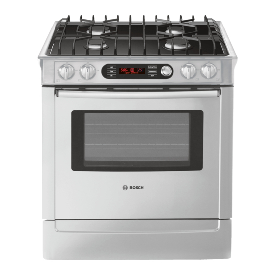
- Page 1 Range Training Manual Electric - Dual Fuel - Gas Free Standing Range – FSR Free Standing Range3 – FSR3 Slide-In Range - SIR Jan. 2008, Iss. 1 58300000130537 ARA EN A...
- Page 2 Jan. 2008, Iss. 1...
-
Page 3: Table Of Contents
Table of Contents Cautions and Conventions Model Number Explanation Data Plate Installation/Service Tools Product Description – Touch and Turn Control Control Panel Display Control Panel Display Options Control Panel Display – Features Oven Features Electric Oven Elements Available Cooking Modes – Electric Range Product Description –... - Page 4 Table of Contents Cont’d Operation – Oven Control Voltage Checks at the Interface Board (clock) Power Relay Board Connections – Electric Oven Power Relay Board Connections – Gas Oven Operation of the Electric Oven Element Cycle Charts Operation of the Oven Gas Burner Electric Top –...
- Page 5 Table of Contents Cont’d Disassembly – SIR – Gas/Dual-Fuel Maintop Motorized Latch Assembly & Door Switch – FSR Motorized Latch Assembly & Door Switch – FSR3/SIR Disassembly – Access to Elements Resistance Checks – Element Terminals Disassembly – Touch & Turn Control Reassembly –...
- Page 6 Alphabetical Table of Contents Bake Element & Warming Element Access Model/Feature Matrix – FSR3-SIR Board Configuration – FSR3-SIR (FD8601-Current) Model/Feature Matrix Legend and Notes Calibrate the Thermostat (change the offset) Motorized Latch Assembly & Door Switch – FSR Cautions and Conventions Motorized Latch Assembly &...
-
Page 7: Cautions And Conventions
• Get help when lifting heavy pieces. • All the parts of the Bosch range are engineered to fit and operate to maximum efficiency. DO NOT discard any part or neglect to fully replace any part unless specifically instructed by Technical Support. -
Page 8: Model Number Explanation
Model Number Explanation Example – HDI 7282 U /02 (HDI7282U/02) The first three letters indicate product type: HDI – Dual Fuel SIR, HDS – Dual Fuel FSR, HEI – Electric SIR, HES – Electric FSR, HGS – Gas FSR The first two numbers indicate the level of features: 25 –... -
Page 9: Data Plate
Data Plate The data plate shows the model number and FD number, It is located on the range front frame behind the storage/warming drawer front panel. To view the data plate the storage/warming drawer will need to be opened at least six inches. The first 4 digits of the FD number designate the year/month the model was produced. -
Page 10: Installation/Service Tools
Installation/Service Tools The following are most of the tools and parts necessary for installation and may be necessary for service: • 1¼ in. (31.8mm) wrench • 30 (at least) Amp power supply cord kit (not necessary for Canadian installation) • Towel or cardboard to protect surfaces •... -
Page 11: Product Description - Touch And Turn Control
Product Description -- Touch and Turn™ Control Powerful technology made easy to use. Functions are selected with the touch-through-glass sensor pad, then all settings are adjusted with one central dial. Jan. 2008, Iss. 1... -
Page 12: Control Panel Display
Control Panel Display Clear text display • • Intuitive operation • Automatic help prompt • Animated display • Indicates preheat temperature • Chime tones to indicate operation • Select menu • Displays oven & warming operations Jan. 2008, Iss. 1... -
Page 13: Control Panel Display Options
Control Panel Display - Options “Lock Keys” Beep volume • • NOTE: 3 beeps indicate an invalid • Sabbath mode selection operation • Oven calibration • Visible clock or no clock • English, French or Spanish • Demonstration mode • F or C degree display •... -
Page 14: Control Panel Display - Features
Control Panel Display - Features Electronic Thermostat: The oven regulates temperature by using a premium sensor with state of the art software to control the elements. Temperatures can be set from 100F to 550F in 5 degree increments. Digital Display Window: The range has a full text display window. The window displays: •... -
Page 15: Oven Features
Oven - Features Cooking Modes: 10 different cooking modes make the range one of the most versatile ovens on the market today. • Bake • Automatic Temperature Probe • Convection Bake • Dehydrating • Convection Roast • Proof Mode • Broil •... - Page 16 Oven – Features (Cont’d) Delayed Start Cooking: User can set the oven to come on at a specific time, and cook for a specific amount of time. Two Timers: Timing is easy with built in timers that beep and acknowledge time is up. Self-Clean with Rack Removal Reminder: Self-cleaning is an automatic 4 hour cycle, or it can be manually set from 3 to 5 hours.
-
Page 17: Electric Oven Elements
Oven Elements Broil Element: 240V at 3,600 watts 10-pass broil element. Bake Element: 240V at 2,000 watts 8-pass bake element. Takes 10 to 13 minutes to reach 350F in bake mode Convection Element: Electric range 240V at 1,100 watts Gas range 120V at 400 watts Warming Drawer Elem:120V at 400 watts Convection Fan:... -
Page 18: Available Cooking Modes - Electric Range
Available Cooking Modes – Electric Range Cooking Mode Symbol Default Range Elements Convection Bake 325F 100F – 525F Upper, lower and third rear Reg. Bake 350F 100 – 550F Upper and lower Convection 325F 100 – 525F Upper and lower Roast Reg. -
Page 19: Product Description - Oven Cavity
Product Description - Oven Cavity • 25” extra-wide oven cavity (4.6 cu. Ft.) • Six rack positions • Telescopic Rack…allows users to check and view food without having to pull the cookware out of the oven. Holds up to 50lbs. •... -
Page 20: Product Description - Warming Drawer
Product Description - Warming Drawer • Electronically controlled temperature via sensor • 400 watt element mounted under drawer, safe for take out containers • Full extension ball bearing glides • 1.3 cu. ft. The warming drawer is secondary to other cooking modes in the control. -
Page 21: Product Description - Dual Fuel & All Gas Range Top
Product Description - Dual Fuel & All Gas Range Top • Pro-Style continuous grates • Low-profile to countertop • Power-Sim Burner (Diffuser Burner) • Sealed burners • Optimized burner spacing • Electronic ignition • Precision Flame Control Jan. 2008, Iss. 1... -
Page 22: Dual Fuel & All Gas Range Top - Features
Dual Fuel & All Gas Range Top - Features Burner Ratings: • RF Burner Power-Sim – 15,000 to a low of 1200 but with cap takes heat output down to 400 to 500 BTUs • RR Burner 800 – 5,500 •... -
Page 23: All Gas Range Oven - Features
All Gas Range Oven - Features • Bake…17,000 BTUs • Broil…14,500BTUs • Electronically controlled • Flame diffuser • Even heat distribution • Glow-bar silicon carbide igniter • Low profile cover for more usable cooking surface Jan. 2008, Iss. 1... -
Page 24: All Electric Range - Electrical Connections
Electrical Connections All Electric - Requires 50 Amp 120/240 VAC or 120/208 VAC. Dedicated circuit preferably with a four wire connection, however where local codes and ordinances permit grounding through the neutral and / or conversion to four wire is impractical, unit may be connected to the power supply via a three wire connection. - Page 25 Electrical Connections (Cont’d) Jan. 2008, Iss. 1...
- Page 26 Electrical Connections (Cont’d) Jan. 2008, Iss. 1...
-
Page 27: Lp Conversion
LP Conversion Conversion the Gas or Dual-Fuel range is completely explained in the Bosch Range LP Conversion Manual and comes with every all-gas and dual-fuel model. The cooktop orifice placement is as follows: LF – Orifice #101 – 11000 BTU (NG - #165 – 12500 BTU) RR –... -
Page 28: Door Removal
Door Removal Jan. 2008, Iss. 1... -
Page 29: Operation - Oven Control
Operation - Oven Control Connector to Power Relay Board from User Interface Board (clock) Connector to User Interface Board (clock) from Power Relay Board When the range is powered up, the interface board receives the voltages at X2 from the power relay board shown in the chart on the next page, and the clock illuminates. -
Page 30: Voltage Checks At The Interface Board (Clock)
Voltage Checks at the Interface Board (clock) 1- 1.5 VDC 2 - 0 VDC 3 - 0 VDC 4 - 5 VDC 5 - 0 VDC 6 - 8 VDC 7 - 0 VDC 8 - 32 VDC Remove connector from board. Set scale to +50VDC. -
Page 31: Power Relay Board Connections - Electric Oven
X3 Wiring Harness to Interface Board Lamps X6 Latch Switches Convection Motor X5 Door Switch Latch Motor X7 Meat Probe X21 Neutral X25 Warm Drawer Sensor X22 K6 out to Warming Ele. X8 Oven Sensor X24 L1 (Red) Input to K6, K7,K8 &... -
Page 32: Power Relay Board Connections - Gas Oven
X3 Wiring Harness to Interface Board Lamps X6 Latch Switches Convection Motor X5 Door Switch Latch Motor X7 Meat Probe X21 Neutral X25 Warm Drawer Sensor X22 K6 Out to Warming Ele. X8 Oven Sensor X24 L1 Input to K6, K7,K8 & K10 Power Relay Board Connections –... -
Page 33: Operation Of The Electric Oven
Operation of the Electric Oven Touch [Bake] and set temperature at the control. The relay board receives input and checks resistance of sensor. If heat is required the following relays will close: K3 & K4 for the bake element and K1 & K2 for the broil element. -
Page 34: Element Cycle Charts
Element Cycle Charts CONVECTION BAKE MODE CONVECTION BAKE MODE Jan. 2008, Iss. 1... - Page 35 Element Cycle Charts Cont’d Jan. 2008, Iss. 1...
-
Page 36: Operation Of The Oven Gas Burner
Operation of the Oven Gas Burner Touch [Bake] and set temperature at the control. Relay board receives input and checks resistance of sensor. If heat is required, Bake relay K11 is closed. 120VAC is sent to the gas safety valve. The glow igniter which is wired in series with the valve starts to heat up, as it does the voltage drops across the valve. -
Page 37: Electric Top - How The Elements Heat
Electric Top -- How the Elements Heat Cont’d L2 N L2 N Jan. 2008, Iss. 1... -
Page 38: How To Replace The Interface Board (Clock) - Fsr (Fd8306-8507)
How to Replace the Interface Board (clock) – FSR (FD8306-8507) Remove the knob: It is a tight fit, wrap some tape around the knob & pull gently on the ends to remove. Remove the locknut Remove upper rear access panel, remove connector from board, remove the 6 screws holding the board. Reassemble new board in reverse order after checking the board configuration. - Page 39 How to Replace the Interface Board (clock) – FSR (FD8306 – FD8507) Cont’d All interface boards are programmed for the MEDIUM featured model initially from the supplier, for example HXS24XU (HX24XXU): For the MOST featured models HXS25XU (HX25XXU) either one of the tabs should be snapped off.
-
Page 40: Model/Feature Matrix - Fsr3-Sir
Model/Feature Matrix – FSR3 & SIR NON- CONVECTION CONVECTION MODEL BAKE BROIL BAKE BROIL ROAST DRWR SELF DEHY PROBE PROOF WARMING PROG CONV CLEAN MENU ELECTRIC BASIC GOOD FSR3 BETTER BEST & SIR US/ BETTER CANADA BEST BASIC ELECTRIC GOOD CANADA FSR3 BETTER... -
Page 41: Model/Feature Matrix Legend And Notes
Model/Feature Matrix – Legend and Notes X: Standard Configuration X*: Electric Good ONLY, Convection Bake parameters are difference from Convection Bake – Better, Best and Pro models XX: Basic has proofing and warming modes within bake temperature select XXX: better, best and Pro US and Canadian Electric FSR, Electric and DF SIR Bake cycle utilizes Convection Bake preheat XXXX: Better, Best and Pro Gas FSR utilizes a 120V 400W electric element during convection cooking preheat and cooking cycle and dehydrate NOTES: The probe is only required to work with the Best &... -
Page 42: Board Configuration - Fsr3-Sir (Fd8601-Current)
Board Configuration – FSR3/SIR (FD8601 – Current) The keypad interface for the control is located on the glass panel. The control display board is mounted behind. Communications between the display board and the power board automatically configure the control for gas or electric range and if it is an FSR3 or SIR. Service Configuration Mode is accessed only when the unit is plugged in (that is, the unit is unplugged, and then plugged back in) and the display shows CLOCK and the 12 is flashing. - Page 43 Board Configuration – FSR3/SIR Cont’d MODEL 1 Best SIR Electric MODEL 2 Better SIR Electric MODEL 3 Better SIR Dual Fuel MODEL 4 Best SIR Dual Fuel MODEL 5 Good FSR3 Electric NOTE: Do not try to do the MODEL 6 Better FSR3 Electric MODEL 7 Best and Pro FSR3...
-
Page 44: Location Of Components - Dual Fuel & All Gas - Fsr/Fsr3
Location of Components - Dual Fuel & All Gas – FSR/FSR3 Relay Board Spark Module Convection Motor Access to warming Gas regulator & drawer element Gas safety valve connection point Jan. 2008, Iss. 1 terminals... -
Page 45: Regulator - Dual Fuel & All Gas Range
Regulator - Dual Fuel & All Gas Range Open allows gas flow The regulator has a shut-off valve installed. There have been field reports of this valve being shut off during installation. If there is no gas flow to the components, check that the valve has not somehow become closed. -
Page 46: Maintop - Dual Fuel And All Gas Range - Fsr/Fsr3
Maintop - Dual Fuel & All Gas Range – FSR/FSR3 To replace the jet assemblies, gas manifold, and tubing, you must first remove the burner bases, knobs, and the manifold cover panel with trim caps. Burner Base – The burner bases are fastened to the maintop with two screws per base. The part number of the screw is 423478. -
Page 47: Disassembly - Access To Maintop - Fsr/Fsr3
Disassembly - Access to Maintop – FSR/FSR3 Tabs No need to remove these screws Slots Remove knobs first if unit has mechanical controls or is a gas top. Remove the two screws under the front panel, support the panel as you take out the second screw so that it won’t fall. Panel is also held in place with two support tabs which fit into slots on sub-panel Remove these... - Page 48 Disassembly - Access to Maintop – FSR/FSR3 Cont’d Remove the screws which hold the 2 rear panels and Ground disconnect the ground screw Screw from the maintop support Lift the maintop a couple of inches to disengage the locking tabs and slide towards the front of the unit. Lift the front of the maintop and fold back against the control panel.
-
Page 49: Disassembly - Sir - Elec/Df Control Panel
Disassembly – SIR – Elec/DF Control Panel The Slide-In Range (SIR) has a different access to the control board, valves and valve switches, and elements. This requires removal of the control panel. To remove the control panel: Locate the four screws holding the control panel to the frame – 2 on each side. It is not necessary to remove the knobs and bezels to remove the panel. -
Page 50: Disassembly - Sir - Electric Maintop
Disassembly – SIR – Electric Maintop It is necessary to remove the maintop to access the elements and the hot indicator bracket and light. The maintop is held down by ball studs and one screw in the back. To remove the maintop: Remove the rear screw Lift the maintop off the ball studs (this may require a little effort). -
Page 51: Disassembly - Sir - Gas/Dual-Fuel Maintop
Disassembly – SIR – Gas/Dual-Fuel Maintop It is necessary to remove the maintop to access the jet assemblies. The maintop is held down by ball studs and one screw in the back. To remove the maintop: Remove the rear screw Lift the maintop off the ball studs (this may require a little effort). -
Page 52: Motorized Latch Assembly & Door Switch - Fsr
Motorized Latch Assembly & Door Switch - FSR Remove 2 screws from front frame Latch can be accessed from under the cooktop Latch Switches Latch Motor Plunger Light Switch Jan. 2008, Iss. 1... -
Page 53: Motorized Latch Assembly & Door Switch - Fsr3/Sir
Motorized Latch Assembly & Door Switch – FSR3 & SIR If the door latch in an FSR3 or SIR unit need repairing or replacing, it is most likely due to motor failure. The motor is accessible on the back of the range. DUE TO THE DIFFICULTY, IT IS NOT RECOMMENDED TO REMOVE THE ENTIRE DOOR LATCH ASSEMBLY. - Page 54 Motorized Latch Assembly & Door Switch – FSR3 & SIR Cont’d After being sure that you have the correct latch, follow these steps to install: Completely remove the old latch by disconnecting the switch connections and removing the screws. Lay aside the screws for use in installing the new latch. Carefully snip and remove the two cable ties holding the yellow, black and white wire bundle together.
- Page 55 Motorized Latch Assembly & Door Switch – FSR3 & SIR Cont’d When properly installed the new latch should look like this photo. Jan. 2008, Iss. 1...
-
Page 56: Disassembly - Access To Elements
Disassembly - Access to Elements Each pair of elements are held in place by a single bracket and tension clips. Retaining Brackets Tension Clips Jan. 2008, Iss. 1... -
Page 57: Resistance Checks - Element Terminals
Resistance Checks - Element Terminals Turn off power before beginning resistance checks LF Triple Element Right Front Single 2500 Watts Element 1200W 2-1 70.7 Ohms 2-4 46.3 Ohms 2-4 71.3 Ohms 2-3 63 Ohms Right Rear Double Element 1900W Left Rear Single Element 2-3 50.6 Ohms 1500W 2-4 68.5 Ohms... -
Page 58: Disassembly - Touch & Turn Control
Disassembly – Touch & Turn Control Disconnect wires as needed. Be sure to check all wiring connections – color and designator. Remove 2 screws holding Support bracket is held with 2 cover screws Lift board up and out. CAUTION: Take care not to break the plastic board standoffs. -
Page 59: Reassembly - Control Board - Fsr
Reassembly - Control Board - FSR The control board must be reassembled so 4 of the 6 light blue standoffs (“pins”) engage the 4 holes in the metal plate glued to the Ceran glass maintop. NOTE: The other 2 standoffs do not engage any holes in the plate. - Page 60 Reassembly -- Control Board – FSR Cont’d Before mounting the control board, make sure each of the 6 light blue standoffs (“pins”) are inserted properly into the component boards. The two boards should be parallel. In addition, make sure there is no debris between the touch pads and the glass, the board is fully inserted, and the pads are making good contact with the glass.
-
Page 61: Access - Bake Element & Warming Element
Access - Bake Element & Warming Element Warming element removed from front by removing the drawer View from Front Back of Range Remove this cover for access to the warming drawer element terminals Rear Remove this cover for access to the bake element Jan. -
Page 62: Range Test/Service Program - Fsr - (Fd8306-8507)
Range Test / Service Program – FSR - (FD8306 – FD8507) The range control has a service program that can be accessed by the service technician to check component and /or function. To enter the service program, do the following: Press [Cooking Mode], [Temperature], and [Start] simultaneously for 5 seconds…... - Page 63 Range Test / Service Program – FSR - (FD8306 – FD8507) Cont’d Touch [Start] and LIGHT will display, at this point the light function can be tested by touching [Start] again, or use the rotary control knob to scroll through the different test functions. To check a particular function rotate to that function then touch [Start].
-
Page 64: Range Test/Service Program - Fsr3 And Sir - (Fd8601-Current)
Range Test / Service Program – FSR3 and SIR - (FD8601 – Current) To access this mode in all models except the 300 series, press and hold [Temperature] and [Time] for 5 seconds. For the 300 series only, press and hold [Broil] and [Time] for 5 seconds. - Page 65 Range Test / Service Program – FSR3 and SIR - (FD8601 – Current) Cont’d Where any element or device relays are called to be active, the double line breaker relay must be activated as well to allow current to flow for measurements by technicians. When [Temperature] (or [Broil]) and [Time] are held for 5 seconds the control goes into a non-user mode with the display showing TEST.
-
Page 66: Service (Electric Or Gas Default)
Service (Electric or Gas Default) The display shows SERVICE. Pressing [Start] displays LIGHT and activates the control into manually stepping through a series of eight functions. To select any of the functions rotate the selection knob. The display shows LIGHT, CONV. FAN, COOLING FAN, COOKTOP ENABLE (if electric), RING, BROIL, BAKE, DRAWER, SENSOR and LATCH. - Page 67 Service (Electric or Gas Default) Cont’d Function 2: Display CONV FAN (if applicable for version) Press Start to activate the convection fan relay. Display ON Press Start to de-activate the convection fan relay. Display CONV FAN Allow user to continue toggling. Rotating the selection knob will de-activate the fan relay (if on) and scroll display to function select.
- Page 68 Service (Electric or Gas Default) Cont’d Function 2B: 1. Display COOKTOP ENABLE (Electric Canadian FSR3 only) 2. Press Start to activate the cooktop enable relay. 3. Display ON 4. Press Start to de-activate the cooktop relay. 5. Display COOKTOP ENABLE 6.
- Page 69 Service (Electric or Gas Default) Cont’d Function 4: Display BROIL Press Start to activate the broil relay for up to 120 seconds. Display ON Press Start to de-activate the broil relay. Display BROIL Allow user to continue toggling. While broil element or gas burner is on, the controller times for 120 seconds. If the user does not turn off broil relay within the 120 seconds the controller turns off automatically and goes to step one.
- Page 70 Service (Electric or Gas Default) Cont’d Function 6: Display DRAWER (if applicable for model) Press [Start] to activate the warming drawer element relay. Display ON Press [Start] to de-activate the warming drawer element relay. Display DRAWER Allow user to continue toggling. Rotating the selection knob will de-activate the warming drawer relay (if on) and scroll display to function select (Light, Fan, Ring, etc.).
- Page 71 Service (Electric or Gas Default) Cont’d Function 8: Display LATCH Press [Start]. The control activates the door latch and operates as if in normal self-clean mode and checks for switch logic and time out functions. Once latch is locked, the motor stops and the icon is steady.
-
Page 72: Fault Codes And Operations
FAULT CODES and OPERATIONS CODE DESCRIPTION WHEN CHECKED FAULT LIMIT Meat probe failure during test or service mode Only during test or service None Oven sensor failure during test or service mode Only during test or service None Warming drawer sensor failure during test or service mode Only during test or service None Oven temperature sensor failure... - Page 73 FAULT CODES and OPERATIONS Cont’d F141 Slave micro not functioning Always 1 Min. F151 EEPROM failure or communication circuit failure Cook or clean programmed 1 Sec F153 User interface too hot Always 1 Sec. F154 Power board too hot Always 1 Sec.
-
Page 74: Faqs - Frequently Asked Questions
FAQs – FREQUENTLY ASKED QUESTIONS When is the convection fan for convection bake and convection roast supposed to come on – when the temperature is reached or is it timed? Gas Range – The convection fan does not come on while in preheat for Convection Bake and Convection Roast, but will turn on when the preset temperature is reached OR at 6 minutes –... - Page 75 FAQs – FREQUENTLY ASKED QUESTIONS Cont’d Electric Range - Better/Best Models Convection bake uses heat from the lower heating element and a third element located behind the back wall. The convection fan circulates the heat. NOTE: The broil element operates during preheat but not while cooking. Convection roast uses heat from the top and bottom elements as well as heat circulated by the convection fan.
- Page 76 FAQs – FREQUENTLY ASKED QUESTIONS Cont’d How do you get the door light to remain on after opening and shutting the door? The oven light can only be turned on manually using the control panel. Once the door is opened and closed, the light will turn off and you must use the control panel to turn it on again.
-
Page 77: Range Troubleshooting/Service Tips
SIR and FSR3 ranges, as well. In early releases of the Bosch SIR there was an issue of noise from the hall-effect fan at the rear of the cabinet. If you receive a call regarding this issue there is a sound dampening kit – 478719 - that can be ordered. -
Page 78: Calibrate The Thermostat (Change The Offset)
Calibrate the Thermostat (Change the Offset) The calibration operation is more fully explained in the Care and Use Manual. Touch [Cooking Mode] & keep your finger on there until SELECT FUNCTION appears (about 5 secs.) Using control knob, scroll through menu until OVEN TEMP OFFSET appears. - Page 79 Calibrate the Thermostat (Change the Offset) Cont’d Using the control knob scroll through the temperature options. The temperature ranges from –25F to + 25F. Select the number of degrees that the temperature needs to be changed by and touch [Start]. Display will show SELECT FUNCTION, touch [Off] to complete the change.
-
Page 80: Wiring Diagrams & Schematics
Wiring Diagrams & Schematics There is a wiring diagram & schematic on the rear cover of each range. Jan. 2008, Iss. 1... -
Page 81: Test
Test 1. What does HDS mean? 2. What does the C mean in HDS7022C? 3. Where is the data plate located? 4. The display can be set for what languages? 5. What do three beeps mean? 6. Temperature settings are increased or decreased in what increments? 7.