
Related Manuals for TurboChef 3240


Summary of Contents for TurboChef 3240
- Page 1 Accelerating the World of Cooking Service Manual 3 240 F O R T H E T U R B O C H E F H I G H H C O N V E Y O R O V E N...
- Page 3 For further information, call 800.90TURBO +1 214.379.6000...
- Page 4 The information contained in this manual is important for the proper installation, use, mainte- nance, and repair of this oven. Follow these procedures and instructions to help ensure satisfactory baking results and years of trouble-free service. Errors – descriptive, typographic, or pictorial – are subject to correction. Specifications are subject to change without notice.
-
Page 5: Table Of Contents
Table of Contents Safety Instructions Important Safety Information - Please Read First General Safety Information Preventing Oven Damage Reducing Fire Risk Grounding Instructions Power Cord Replacement Specifications and Startup Oven Overview Certifications Dimensions Oven Construction Theory of Operation Power Specifications Ventilation Requirements Gas Derating Gas Setup... - Page 6 TA B L E O F CO N T E N TS Oven Modes Config Mode Smart Card Screen Updating the Firmware Accessing the Fault Count Screen Accessing the Setup Mode Accessing the Test Mode Setup Mode Changing the Display Temperature Edit Option Screen Changing the Display Language Info Screen...
- Page 7 The Blower System Blower Motor Blower Motor Speed Controller (BMSC) The Burner System Air Pressure Switch Burner Transformer Combustion Blower Modulating Gas Valve Ignition Module Troubleshooting Overview of Troubleshooting Fault Code Descriptions Fault Code Troubleshooting F1: Blower Fault F2: Low Cook Temp F3: No Flame F5: CC Over Temp F6: EC Over Temp...
-
Page 8: Safety Instructions
S A F E T Y I N S T R U C T I O N S Important Safety Information – Please Read First Improper installation, adjustment, alteration, service, or maintenance of this equipment can cause property damage, injury, or death. Thoroughly read the installation, operating, and maintenance instructions before installing or servicing this equipment. -
Page 9: Reducing Fire Risk
Reducing Fire Risk If materials inside the oven ignite or if smoke is observed, 1.Keep the oven window closed. 2.Turn off the oven. 3.Disconnect the power cord or shut off power at the fuse/circuit breaker panel. Carefully attend the oven if paper, plastic, or other combustible materials are placed inside the oven to facilitate cooking. - Page 10 i i i S A F E T Y I N S T R U C T I O N S This page intentionally left blank.
-
Page 11: Specifications And Startup
Specifications and Startup... -
Page 13: Oven Overview
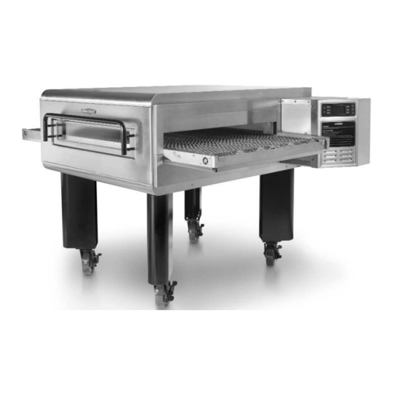
Overview Figures 1 and 2. For part numbers, see the appendix. 1. Air filter, 11.75” x 7.5” (298 mm x 190 mm) 2. Idle button (page 21) 3. Left end bell (page A-12) 4. Right end bell (page A-8) 5. VFD display and keypad (page 21 and A-8) 6. -
Page 14: Certifications
S P E C I F I C AT I O N S A N D S TA R T U P Certifications cULus GAS FIRED LISTED, UL EPH, FCC Dimensions With End Bells Closed - Width: 72.13” (1832 mm) - Depth: w/ window: 55.25”... -
Page 15: Gas Setup
Gas Setup A digital manometer that will read 0.10” WC (2.54 mmH O, 0.249 mb) must be used to properly set all pressures. If the minimum pressure is not set correctly, the oven temperature will slowly rise in stand-by mode and eventually cause cooking issues as well as trip the high limit temperature switch. -
Page 16: Reading The Gas Pressure At Minimum Flame
S P E C I F I C AT I O N S A N D S TA R T U P Reading the Gas Pressure at Minimum Flame 1. Remove either the red or white wire (Figure 4). 2. Attach the electric manometer to the lower tap of the gas valve (Figure 4). -
Page 17: Cleaning
Cleaning... -
Page 19: Cleaning The Oven
Cleaning the Oven Follow the steps below daily to help maintain your HhC oven. Daily Cleaning Procedures Step 1: Prepare the Oven -Press the back/off key (page 9) to turn the oven off. -Ensure cooling down has completed. CAUTION: Injury can occur if oven is not allowed to cool properly before cleaning. -
Page 20: Deep Cleaning Procedures
C L E A N I N G Deep Cleaning Procedures TurboChef recommends deep cleaning the oven once a month (or more frequently depending on use) to ensure optimal performance. Use only TurboChef-approved cleaner. Using any other cleaning product can damage critical parts and may void the oven’s warranty. Step 1 Step 2 Step 3... - Page 21 Step 7: Remove and Clean the Conveyor (requires TWO people) -Position one person at each end of the conveyor. -Lift the conveyor assembly up and then towards the left side of the oven until the conveyor drive chain has enough slack for removal. -Remove the conveyor drive chain.
- Page 22 C L E A N I N G Step 12: Clean the Oven Interior -Spray the bottom and sides of the oven interior with TurboChef Oven Cleaner to -Scrub the oven interior with a nylon scrub pad. -Wipe the oven interior with a clean, damp towel. Step 12 Step 13: Reinstall the Oven Components -Reinstall the lower plenum assembly (if upper nozzle plate was cleaned,...
-
Page 23: Standard Oven Operation
Standard Oven Operation... -
Page 25: Oven Controls
Figure 5: Oven Controls Oven Controls Figure 5 1. Display The display shows current oven operation and/or user programming information. 2. Soft Keys Six soft keys are on the oven controls, three on the left (L1, L2, L3, where L1 = top) and three on the right (R1, R2, R3, where R1 = top). -
Page 26: Cooking A Product
S TA N DA R D O V E N O P E R AT I O N BREAKFAST DINNER OVEN OFF LUNCH DESSERT BREAKFAST DINNER 5:00 3:20 BELT SPEED 2:00 3:00 LUNCH DESSERT BREAKFAST TOP AIR 40 % LIGHTING BELT F 5:00 OVEN TCC = 72F... - Page 27 9 when the user selects a belt speed and MODE the set cooking temperature is lower than the oven’s current temperature. Mode 3: Lighting Mode during which the ignition module applies voltage to the spark rod to start the burner. Happens When...
-
Page 28: Editing A Cooking Profile
S TA N DA R D O V E N O P E R AT I O N Mode 8: Idle Mode during which both blowers are reduced to 30% to save power. All other oven components remain the same. Happens When... -
Page 29: Adjusting The Belt Speed
- ---> (R1) moves the cursor to the right. The cursor starts at the far left character. If ---> is pressed when the cursor is on the far right character, the cursor moves to the far left character. - <--- (L1) moves the cursor to the left. The cursor starts at the far left character. - Page 30 S TA N DA R D O V E N O P E R AT I O N This page intentionally left blank.
-
Page 31: Oven Modes
Oven Modes... -
Page 33: Config Mode
The Config Mode (Figure 9) serves four main CONFIG MODE purposes: 1. To access the smart card screen. 2. To access the fault count screen. 3. To access the SETUP MODE 4. To access the TEST MODE To access the , press the up key CONFIG MODE from the... -
Page 34: Accessing The Fault Count Screen
O V E N M O D E S Accessing the Fault Count Screen Refer to page 29 for fault descriptions. From the CONFIG MODE press R1 to access the fault count screen (Figure 13). The oven will display the number of faults that have occurred since the oven fault counts were last cleared (page 20), the oven’s software was last updated (page 15), or the oven was last... -
Page 35: Changing The Display Language
Changing the Display Language NOTE: This feature is not available on all oven models. From the setup menu screen, press R1 to change the language (Figure 14): -English -French -German -Spanish Info Screen The info screen (Figure 17) is used to display the following information in an easy to access place: - The oven’s serial number... -
Page 36: Accessing The Burner Control Screen
O V E N M O D E S Accessing the Burner Control Screen From screen 1 of the TEST MODE page 17), press L1 to access the burner control screen (Figure 21). Use this mode to set gas pressures (see page 3). To change the burner’s setting, -Press L1 to set the burner to full (or to -light the burner). -
Page 37: Entering A New Serial Number
Shows whether or not the igniter is on. 0% = OFF, 100% = ON. Shows the voltage of the power supply. Bottom Display Line The bottom display line shows enabled inputs and outputs on the control board. The numbers 1-10 indicate the different bottom display line, which are explained below. -
Page 38: Initiating A Burn-In Test
O V E N M O D E S Initiating a Burn-In Test NOTE: Burn-in tests are for manufacturing use only. DO NOT initiate a burn-in test unless expressly instructed by TurboChef. To initiate a burn-in test, Press L2 (Figure 19, page 17) on screen 2 of the The burn-in test (Figure 25) runs the oven for 45 minutes to ensure correct oven operation. -
Page 39: Oven Systems
Oven Systems... -
Page 41: The Control System
The Control System This section contains information about the following components: -Control Board -Display -EMI Filter -Fuses -High-limit Thermostat -Idle Button -Keypad -Power Supply - 24VDC (Domestic) -Power Supply - 24VDC (International) -Relay (K3 - Gas) -Relay (K4 - Ignition) -RTD -Smart Card Reader -Speaker... -
Page 42: Power Supply - 24Vdc (International)
O V E N S YS T E M S b) If terminal resistance is incorrect, replace the power supply. 3. If correct voltage is present, disconnect the output wires and check output (-OUT & +OUT) for 24 VDC. 4. If voltage is present with output wires disconnected and not present when the wires are connected, inspect the wire harness for damage or shorts. -
Page 43: Rtd
3. If coil resistance is correct (585 k W): a) Apply line voltage to the unit. b) Check for 24 VAC at the coil of the relay when the unit is calling for heat. c) Check the state of the contacts. -If the normally open contacts (7 &... -
Page 44: Gear Drive (Conveyor Motor) Speed Controller (Cmsc)
O V E N S YS T E M S 3. If the resistance readings are correct, reconnect the motor wiring and then apply line voltage to the unit and check for voltage applied to the motor windings. 4. If no voltage is present, ensure the CMSC is operating properly (see below). -
Page 45: The Blower System
Accessing Parameters WARNING: DO NOT perform this procedure unless instructed by TurboChef.Changing the parameters to other than those preset by TurboChef can damage critical oven components. NOTE: “Motor Rated Speed” (07) is RPM of motor before gearbox, not after. 1. Open the right end bell (page 1). 2. -
Page 46: The Burner System
O V E N S YS T E M S 2. Check the input voltage on terminals L1 & L2 (208-240 VAC) and the DC voltage input on terminals 2 & 5 (0.1-10 VDC). 3. If no voltage is present, inspect the wire harness for damage or shorts (page 45). -
Page 47: Modulating Gas Valve
From Expected Resistance Primary Black White (240 VAC Input) 28.1 Black Blue (240 VAC Input) 53.1 Black Red (240 VAC Input) 62.4 Yellow Yellow Secondary 0.80 Figure 33: Burner Transformer Ohm Chart Combustion Blower The combustion blower is a 3000 RPM, 208- 240 VAC, 0.33 A, 50/60 hz, blower motor. - Page 48 O V E N S YS T E M S 1. Shut off the gas supply. 2. Disconnect the wire spark cable from the stud terminal of the ignition module. This will isolate the burner spark rod from the ignition module. 3.
-
Page 49: Troubleshooting
Troubleshooting... -
Page 51: Overview Of Troubleshooting
Overview of Troubleshooting This section contains information on the following: - Fault code descriptions - Fault code troubleshooting - Non-fault code troubleshooting Fault Code Descriptions Fault codes are logged in a fault counter (page 16) for troubleshooting. Upon completing the service call and restoring successful operation of the oven, the technician should clear all faults (see page 20). -
Page 52: F5: Cc Over Temp
T R O U B L E S H O OT I N G F8: High Limit Tripped This fault is displayed if the high limit switch trips. The switch trips when the high limit probe reads approximately 600°F (315.5°C). The fault is cleared from the display when the high limit switch is manually reset. -
Page 53: Fault Code Troubleshooting
Fault Code Troubleshooting From , you can test separate oven components to help diagnose an issue. To access TEST MODE , see page 16. MODE Open the Right Open Left End Bell. End Bell. Is a fault code Is a fault code present on the present on the BMSC? -
Page 54: F2: Low Cook Temp
T R O U B L E S H O OT I N G Troubleshoot the blowers (page 31). Troubleshooting: F2: LOW COOK TEMP (Low Temp During Cook) Restart the oven, access the TEST MODE both the top and bottom blowers. Are the status indi- cators at location 6, 7, 8, and 9 present (pages 18-19). - Page 55 This page intentionally left blank.
-
Page 56: F3: No Flame
T R O U B L E S H O OT I N G Turn the oven off and then on. Does the burner ignite and the fault clear? Operate normally. Replace the wire spark cable (page A-14). Is inlet gas pressure present? Inlet gas pressure must be between 6”... - Page 57 Does the burner trans- former have 24 VAC output (page 26)? Are the contacts on the high limit thermostat closed (page A-14)? Is the air pressure switch closed? Inspect or replace the high limit thermostat (page A-14). Is voltage applied to the combustion blower? Replace the...
-
Page 58: No Display
T R O U B L E S H O OT I N G Open the rear access panel (page 1). Remove the white wire from the modu- lating gas valve (page A-14). Does the unit continue to heat? Reset the minimum flame gas pressure (page 3). - Page 59 Troubleshooting: F6: EC OVER TEMP (EC Over Temp) Are the air filters on the left end bell clean (page 1)? Open the left end bell. Are the cooling fans running? Check for -Obstructions in the cooling tunnel. -Dirt or debris in the cooling fan blades. -A heat source near the filter.
-
Page 60: F7: Rtd Fault
T R O U B L E S H O OT I N G Replace the RTD (page A-8). Replace RTD (page A-8). Reset and determine why it tripped - over temp, blower failure, etc. Check if the high limit probe or RTD is damaged or defec- tive, replace if needed (page A-8). - Page 61 F9: BELT FAULT (Total Belt Run Failure) Remove obstruction or replace/repair the conveyor and restart the oven. Is the F9 fault code still present? Operate the oven as you would normally. Correct wiring (page 45). Check that the CMSC settings correctly correspond with TurboChef settings.
-
Page 62: F10: Air Pressure Switch Fault
T R O U B L E S H O OT I N G Are all the contacts on the high limit thermostat closed? Investigate the reason for the high limit tripping. If the thermostat is defective, replace it (page A-14). Is the combustion blower running? Is line voltage... -
Page 63: Non-Fault Code Troubleshooting
Non-Fault Code Troubleshooting This section provides troubleshooting tips for issues that may occur independently of an oven fault. Is the oven in an area of moderate temperature (120ºF [49ºC] or cooler)? Does the oven have room to ventilate (not tightly enclosed by other appliances or fixtures)? Is the air filter dirty and/or... -
Page 64: Food Not Cooking Properly
T R O U B L E S H O OT I N G Does the problem occur for all programmed recipes? For example, are all recipes under- cooked/overcooked/etc.? Are there any fault codes present (page 29-30)? Troubleshoot the fault(s) using the steps on pages 31-40. -
Page 65: No Keypad Input
Is wiring from the control board to the display (including the rib- bon cable) OK (page 45)? Is 5 VDC present on pin 1 of the J3 connector? (page 45) Replace the display and ribbon cable. (page A-8) Replace the keypad (page A-8). If the problem persists, or if beeps occur when buttons are pressed but commands do not regis- ter on the display, replace the control board... - Page 66 T R O U B L E S H O OT I N G This page intentionally left blank.
-
Page 67: Schematic
Schematics... - Page 70 S C H E MAT I C S...
-
Page 73: Appendix A - Replacing Oven Components
Appendix A - Replacing Oven Components... - Page 75 Replacing Oven Components WARNING: Before removing or replacing any oven component, thoroughly read the safety instructions found at the front of this manual and Oven Systems (pages 21-28). Adhere to all precautions and warnings outlined in these sections, as failure to do so could result in serious injury or death.
- Page 76 A- 2 A P P E N D I X A - R E P L AC I N G O V E N CO M P O N E N TS To Replace This... Item Conveyor Belt Kit, 70/30 Split, Right to Left HHC-6662-2 Cord, Power, 12/3, SOOW, NEMA L620 Cover, Blower Insulation, Lower Cover, Blower Insulation, Upper...
- Page 77 To Replace This... Item Leg Kit, 20-Inch Leg Kit, 26-Inch Literature Packet Manometer Kit, Electronic with Nylon Case Menu, HhC3240 Nutplate, Drive Bracket Panel , Conveyor Drive Pipe and Valve Assembly Plate, Conveyor Drive, Double Plate, Blower Motor, Lower Plate, Blower Motor, Upper Plate, Blower Mounting, Lower Plate, Blower Mounting, Upper Plenum, Lower...
- Page 78 A- 4 A P P E N D I X A - R E P L AC I N G O V E N CO M P O N E N TS To Replace This... Item Weldment, Shaft, Internal Drive Window Kit Wire Harness, Conveyor Drive AC Wire Harness, Cooling Fan...
- Page 79 A- 5 This page intentionally left blank.
-
Page 80: Replacing Items - No Panel Removal Required
A- 6 A P P E N D I X A - R E P L AC I N G O V E N CO M P O N E N TS Replacing Items - No Panel Removal Required WARNING: Before removing or replacing any oven component, thoroughly read the safety instructions found at the front of this manual and Oven Systems (pages 21-28). - Page 81 Item Part Number Caster 102799 Catch, Slotted Eyebrow HHC-6499 Chain Guard HHC-6411 Chin Assembly, Left End HHC-6464 Chin Assembly, Right End HHC-6463 Conveyor Belt Kit, Single, Left to Right HHC-6561-1 Conveyor Belt Kit, Single, Right to Left HHC-6561-2 Conveyor Belt Kit, 50/50 Split, Left to Right HHC-6661-1 Conveyor Belt Kit, 50/50 Split, Right to Left HHC-6661-2 Conveyor Belt Kit, 70/30 Split, Left to Right HHC-6662-1 Conveyor Belt Kit, 70/30 Split, Right to Left HHC-6662-2...
-
Page 82: Replacing Items - Right End Bell
A- 8 A P P E N D I X A - R E P L AC I N G O V E N CO M P O N E N TS Replacing Items - Right End Bell WARNING: Before removing or replacing any oven component, thoroughly read the safety instructions found at the front of this manual and Oven Systems (pages 21-28). - Page 83 Item Blower Motor, Lower Blower Motor Controller (BMSC), Lower Blower Wheel, Lower Bracket, EMI Filter Bracket, Gear Drive Controller Cable, Display, Power, 2-Pin Cable, Display, Ribbon Cable, Smart Card Reader Control Board Cord, Power, 12/3, SOOW, NEMA L620 Cover, Blower Insulation, Lower Display EMI Filter Fuse...
- Page 84 A- 1 0 A P P E N D I X A - R E P L AC I N G O V E N CO M P O N E N TS Gear Drive Assembly Detail Panel, Conveyor Drive Weldment, Shaft, Internal Drive Sprocket, 1”...
- Page 85 Item Part Number Bolt Retainer Bracket HHC-6426 Collar, 5/8-inch Shaft 100257 Gear Drive, Dual Belt HHC-4120 Gear Drive, Single Belt HHC-6538 Geared Hub HHC-6607 Nutplate, Drive Bracket HHC-6396 Panel , Conveyor Drive HHC-6301 Plate, Conveyor Drive, Double HHC-6467 Sprocket, 1" Bore 101906 Spur Gear, 2.75 PD, 1/2-inch Bore 101895...
-
Page 86: Replacing Items - Left End Bell
A- 1 2 A P P E N D I X A - R E P L AC I N G O V E N CO M P O N E N TS Replacing Items - Left End Bell WARNING: Before removing or replacing any oven component, thoroughly read the safety instructions found at the front of this manual and Oven Systems (pages 21-28). - Page 87 Item Blower Motor, Upper Blower Motor Controller (BMSC), Upper Blower Wheel, Upper Bracket, CMSC Bracket, Dual Fan Mounting Combustion Motor Controller (90 , Nat Gas) HHC-6630-3 Combustion Motor Controller (Inline, Nat Gas) Combustion Motor Controller (90 , Propane) HHC-6630-5 Combustion Motor Controller (Inline, Propane) Cover, Blower Insulation, Upper Fan, Cooling, Lower...
-
Page 88: Replacing Items - Burner Compartment Cover
A- 1 4 A P P E N D I X A - R E P L AC I N G O V E N CO M P O N E N TS Replacing Items - Burner Compartment Cover WARNING: Before removing or replacing any oven component, thoroughly read the safety instructions found at the front of this manual and Oven Systems (pages 21-28). - Page 89 Item Air Pressure Switch Bracket, Thermostat Burner Assembly Clamp, Conduit, 1/2 Nominal, Zinc Combustion Motor (90-degree) Combustion Motor (Inline) - not pictured Flame Sensor Flame Sensor Wire Flame Spreader Gas Valve, Modulating Ignition Module Pipe and Valve Assembly Relay, K4, Sealed, 24 VAC, 20A Shield, Gas Pipe Shutter, Inlet Air Blower Spark Assembly...
- Page 92 For service or information: W I T H I N N O RT H A M E R I C A C A L L Customer Service at 800.90 O U T S I D E N O RT H A M E R I C A C A L L +1 214-379-6000 or Your Authorized Distributor Accelerating the World of Cooking Part Number: HHC-6652/Revision B/May 2008...