Table of Contents
Advertisement
Quick Links
Advertisement
Table of Contents
Troubleshooting

Related Manuals for Cisco cBR Series


Summary of Contents for Cisco cBR Series
- Page 1 Cisco Converged Broadband Routers Hardware Installation Guide First Published: 2015-03-25 Last Modified: 2019-07-31 Americas Headquarters Cisco Systems, Inc. 170 West Tasman Drive San Jose, CA 95134-1706 http://www.cisco.com Tel: 408 526-4000 800 553-NETS (6387) Fax: 408 527-0883...
- Page 2 © 2015–2019 Cisco Systems, Inc. All rights reserved.
- Page 3 C O N T E N T S C H A P T E R 1 What is a Cisco cBR Series Converged Broadband Router Introduction Functional Overview Upstream Data Path Downstream Data Path Cisco cBR-8 Converged Broadband Router Physical Description Slot Numbering—Physical and Logical...
-
Page 4: Table Of Contents
C H A P T E R 5 Installing the Power System in the Cisco cBR Chassis Installing the Power Cassette Module in the Cisco cBR Chassis Installing the FPEM in the Cisco cBR Chassis Installing the Power Module in the Cisco cBR Chassis... - Page 5 Using the Console Port on the Supervisor PIC Using the Auxiliary Port on the Supervisor PIC Cable Management for the Supervisor PIC in the Cisco cBR Chassis Using the USB Port on the Supervisor Card Using the Console Port on the Supervisor Card...
- Page 6 Monitoring the Interface Card in the Cisco cBR Chassis Monitoring the Interface Line Cards in the Cisco cBR Chassis using LEDs Monitoring the Digital Physical Interface Cards in the Cisco cBR Chassis using LEDs C H A P T E R 1 4...
- Page 7 Maintaining the Interface Cards in the Cisco cBR Chassis Maintaining the DOCSIS MAC/PHY Interface and PIC Card Removing the DOCSIS MAC/PHY Interface Line Card from the Cisco cBR Chassis Removing the UCH.8 Connectors from the RF PIC Removing the RF PIC from the Cisco cBR Chassis...
- Page 8 Removing the Air Filter on a Card Installing the Air Filter on a Card C H A P T E R 2 1 Online Insertion and Removal of Cards on the Cisco cBR About OIR What Does an OIR Do?
-
Page 9: C H A P T E
The Cisco cBR supports video including both traditional MPEG video and Video over IP over DOCSIS (VDOC). The advantage of Cisco cBR is the ability to support MPEG video and VDOC in the same platform allowing transition from MPEG to VDOC. The Cisco cBR is a single device that manages the entire RF spectrum of the cable plant. - Page 10 • Assistance with the support of legacy devices in a Videoscape environment • Video cache integration The path from the Cisco CMTS to the cable modem or STB is the downstream, which carries the majority of traffic over the cable interface.
- Page 11 What is a Cisco cBR Series Converged Broadband Router Downstream Data Path 3. The DOCSIS MAC header is removed and another header is added, which includes the SID, the upstream port information, and status bits that indicate whether any errors were detected.
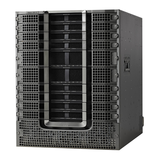
- Page 12 The front card modules plug into the Digital Midplane and the associated Physical Interface Card (PIC) plugs into the rear of the chassis. All permanent connections to the Cisco cBR-8 chassis are made at the rear. Figure 1: Chassis Front View...
- Page 13 What is a Cisco cBR Series Converged Broadband Router Cisco cBR-8 Converged Broadband Router Figure 2: Chassis Rear View with AC FPEM Line Card PIC Lifting Handle Supervisor PIC AC FPEM Fan Module Figure 3: Chassis Rear View with DC FPEM...
- Page 14 • Two Supervisor PICs • Eight Cisco cBR line cards • Eight Cisco cBR RF PIC cards (seven when the chassis is configured in protect mode) or Eight Cisco cBR DPIC cards (if -R line cards are installed) • One Cisco cBR RF PROT PIC card (if the chassis is configured in RF protect mode) •...
- Page 15 What is a Cisco cBR Series Converged Broadband Router Physical Description Figure 4: Basic Dimension The below image shows the overall dimensions of the Cisco cBR-8 chassis with optional cable management and rear door cable protection. Figure 5: Overall Dimension...
- Page 16 Lifting Handles The Cisco cBR-8 chassis has four handles available for lifting. It is recommended to remove all circuit cards before attempting to install the chassis in a rack, but at a minimum, the front Supervisors and line cards should be removed before lifting the chassis with the available handles.
- Page 17 What is a Cisco cBR Series Converged Broadband Router Slot Numbering Physical and Logical Component Slot Numbering Power Supply Modules Numbered from P0 to P5 and these map to the facility power outlet markings on the rear of the chassis.
- Page 18 What is a Cisco cBR Series Converged Broadband Router Slot Numbering Physical and Logical Figure 7: Slot Numbering Front of the Chassis With DC Power Module Figure 8: Slot Numbering Rear of the Chassis With AC Power Module Cisco Converged Broadband Routers Hardware Installation Guide...
- Page 19 What is a Cisco cBR Series Converged Broadband Router Slot Numbering Physical and Logical Figure 9: Slot Numbering Rear of the Chassis With DC Power Module Table 3: Logical Slot Numbering on the Cisco cBR-8 Router Variable Component Description Valid Range/Values Release—Cisco IOS-XE Release 3.15.0S...
- Page 20 What is a Cisco cBR Series Converged Broadband Router Field Replaceable Units Variable Component Description Valid Range/Values 0 to 15 cable-interface-index Interface card MAC domain index of the interface card. logical-channel-index rf-channel Interface card RF channel number on the 0 to 159 (downstream) interface card.
- Page 21 What is a Cisco cBR Series Converged Broadband Router Field Replaceable Units Hardware Module Function Description Facility Power Entry Module (FPEM) (AC/DC) Provides the physical hookup interface and interconnection to the power modules for either the AC or DC input voltage. The digital communication from the power modules to the digital midplane;...
- Page 22 What is a Cisco cBR Series Converged Broadband Router Field Replaceable Units Module Maximum Weight Power Cassette (AC/DC) 17 lbs. Facility Power Entry Module (FPEM) (AC/DC) 15 lbs. Fan Module 4 lbs. 13RU Chassis Estimated Weight (with midplanes and 85 lbs.
- Page 23 Supervisor Cisco cBR-8 Converged Cable Access Router Supervisor 160G The Supervisor is the processor of the Cisco cBR. It consists of a forward processor (FP) complex and route processor (RP) complex. The FP complex performs data forwarding, baseline router packet operations including MAC classification, Layer 2 and the various Layer 3 forwarding, QoS classification, security ACLs, VPNs, policing, shaping, load balancing, and Netflow, egress packet buffering, queueing, and egress packet scheduling functions.
- Page 24 What is a Cisco cBR Series Converged Broadband Router Cisco cBR-8 Converged Cable Access Router Supervisor 160G Figure 10: Supervisor Card Spring-loaded ejector LEDs Tethered I/O door Support rails Plastic latch USB ports Removable air filter Console port Table 9: Physical Specifications of the Supervisor Card...
- Page 25 • CBR-CCAP-SUP-60G—Supervisor Card with 60 Gbps forwarding capacity. It supports a maximum of four interface cards, working in 3+1 protection mode, on the Cisco cBR-8 router. It supports a maximum of 72268 unicast flows or 88268 modular quality of service (MQoS) flows. The maximum number of unicast and MQoS flows supported is 88268.
- Page 26 What is a Cisco cBR Series Converged Broadband Router Cisco cBR-8 Converged Cable Access Router Supervisor 160G Figure 11: Supervisor PIC Ejector lever NME ports Timing port (1 PPS) Console port Timing port (10 MHz) Auxiliary port GPS port Captive screws...
- Page 27 What is a Cisco cBR Series Converged Broadband Router Cisco cBR-8 Converged Cable Access Router Supervisor 160G Table 12: Ports on the Supervisor PIC Port Description SFP+ ports The Supervisor PIC has eight Ten Gigabit Ethernet SFP (SFP+) ports. These ports are used to connect it to the switch or router.
- Page 28 Software features and services • SSD memory (240G) for syslog/debug information/image/package storage ® • Run with the modular Cisco IOS XE Software for the Cisco cBR-8 Converged Cable Access Router • Provide 1+1 redundant-supervisor support • Two Integrated 1x100G NSI (Network Side Interface) backhaul interfaces on Supervisor PIC. The interface can support either QSFP28 or QSFP+ module •...
- Page 29 The Supervisor Card is the route processor of the Cisco cBR and includes integrated backhaul capability. It is installed in the front of the Cisco cBR chassis. The plastic latch maintains the alignment of the spring-loaded ejector with the faceplate. The Supervisor Card has a tethered door to allow access to the ports on its faceplate.
- Page 30 RPLC Replace LED Important Different Supervisor Cards cannot coexist on a Cisco cBR-8 router. We recommend that you install the Supervisor Cards with the same capacity in the chassis to ensure proper redundancy support. Supervisor PIC The Supervisor PIC provides the physical interface to the Supervisor Card. It is installed in the rear of the Cisco cBR chassis.
- Page 31 What is a Cisco cBR Series Converged Broadband Router Cisco cBR-8 Converged Cable Access Router Supervisor 250G Figure 13: Supervisor PIC Ejector lever Timing port (1 PPS) QSFP ports Timing port (10 MHz) Auxiliary port Console port DTI ports LEDs...
- Page 32 What is a Cisco cBR Series Converged Broadband Router Cisco cBR-8 Converged Cable Access Router Supervisor 250G Table 16: Ports on the Supervisor PIC Port Description QSFP ports The Supervisor PIC has two QSFP ports. These ports are used to connect it to the switch or router. These ports provide backhaul connection to the WAN network.
- Page 33 This filter filters the air flowing into the chassis through the perforated grill faceplate. All interface cards in the Cisco cBR-8 chassis are designed for High Availability (HA) with a N+1 redundancy scheme.
- Page 34 A DOCSIS MAC/PHY line card is paired with an RF Physical Interface Card (RF Through PIC or RF Protect PIC). RF Interface Line Cards The Cisco cBR chassis supports the following RF Interface Line Cards: • DOCSIS MAC/PHY SSI Card with two downstream D3.1 modules and one upstream D3.1 module installed. [PID: CBR-LC-8D31-16U31] •...
- Page 35 REPLACE Indicates if the card must be replaced. Downstream PHY Module Each interface line card supports two downstream PHY modules. The Cisco cBR chassis supports the following downstream PHY module versions: • Downstream D3.0 (supporting DOCSIS 3.0). [PID: CBR-D30-DS-MOD] • Downstream D3.1 (supporting DOCSIS 3.1). [PID: CBR-D31-DS-MOD] Note The Downstream D3.1 module has a green label on it.
- Page 36 • All interface line cards in the chassis must have the same upstream PHY module version; that is all D3.0 or D3.1 modules. • The upstream D3.1 module is supported only with the Cisco IOS-XE Release 3.18.0S and later releases. • If the upstream D3.1 modules are installed with the Cisco IOS-XE Release 3.17.0S, the upstream D3.1 modules will boot up, but not function properly.
- Page 37 What is a Cisco cBR Series Converged Broadband Router DOCSIS MAC/PHY Cards Figure 15: RF Through PIC Downstream ports DS0 to DS7 LEDs Upstream ports US0 to US7 and US8 to US15 Product Identifier (PID) Ejector Lever Table 19: Physical Specifications of the RF PICs...
- Page 38 A DOCSIS MAC line card is paired with an Digital Interface Card (DPIC). Digital Interface Line Cards The Cisco cBR chassis supports the following Digital Interface Line Cards: • DOCSIS MAC SSI Card (40Gbps). [PID: CBR-CCAP-LC-40G-R] Cisco Converged Broadband Routers Hardware Installation Guide...
- Page 39 • DOCSIS MAC SSI Card (80Gbps). [PID: CBR-CCAP-LC-G2-R] Digital PICs The Cisco Digital Physical Interface Card (DPIC) is used to connect a cBR-8 DOCSIS MAC Line card to an external Remote PHY Node Device (RPD) or Remote PHY Shelf product.
- Page 40 What is a Cisco cBR Series Converged Broadband Router DOCSIS MAC Cards Link LEDs LEDs QSFP Ports Product Identifier (PID) Plastic latch Table 21: Physical Specifications of the 2x100G DPIC Unit Dimensions Width 10.96 in (27.8cm) Height 1.43 in (3.6cm) Depth 7.32 in (18.6cm) with...
- Page 41 If the QSFP-100G-SM-SR module is used in the DPIC 100G card, the cBR-8 router chassis ambient temperature must be limited to 50ºC at sea level. Power System The Cisco cBR chassis is powered using AC or DC power inputs. The power system consists of the following modules: • Power Cassette Module •...
- Page 42 What is a Cisco cBR Series Converged Broadband Router Power System • For the AC-powered Cisco cBR with N+1 redundancy, the chassis must have at least four operational AC Power Modules to be functional. • For the AC-powered Cisco cBR with 1+1 redundancy, the chassis must have six operational AC Power Modules to be functional.
- Page 43 • Power interconnection from the Power Modules to the midplane bus bar. The FPEM is installed in the rear of the Cisco cBR chassis. It is field replaceable to allow the facility to change from AC to DC power, or vice versa, without replacing the chassis.
- Page 44 What is a Cisco cBR Series Converged Broadband Router Power System Mounting flange Power Enable LED Handle AC power input connector Power switch Figure 20: DC FPEM Mounting flange Negative lead Handle Positive lead Power switch Power Enable LED Terminal block cover...
- Page 45 3.85 in (9.78 cm) Maximum weight 15 lb (6.8 kg) Both AC and DC FPEMs have a power switch to enable power to the entire Cisco cBR chassis. The AC FPEM has the following LED: • POWER ENABLE—Power status LED The DC FPEM has the following LEDs: •...
- Page 46 What is a Cisco cBR Series Converged Broadband Router Power System Figure 22: DC Power Module Handle Screw Table 24: Physical Specifications of the Power Module Unit Value AC Power Module 16.94 in (43.02 cm) Depth Width 4 in (10.16 cm) Height 1.6 in (4.06 cm)
- Page 47 Fan Module Fan Module The Cisco cBR-8 router has multiple modular Fan Modules installed in the rear to supply cooling air and have five Fan Module bays in the rear of the chassis. The bays are numbered from P10 to P14.
- Page 48 Cooling System of the Cisco cBR Chassis The Fan Modules in the Cisco cBR chassis are controlled by the Supervisor Card. Until the Supervisor Card boots up, the fans spin at default speed of 11000 RPM. After Supervisor Card boot-up, the Supervisor Card controls the fan speeds, based on the temperature of the air entering the chassis and the barometric pressure reported by the sensors in the Fan Modules.
- Page 49 Note You can remove and install an air filter when the Cisco cBR router is powered on and working. Cisco IOS-XE Software The Cisco cBR Series Converged Broadband Router (Cisco cBR) runs the Cisco IOS-XE software, which is stored on the Type II PCMCIA flash memory disks stored in the two PCMCIA slots in the primary route processor module.
- Page 50 What is a Cisco cBR Series Converged Broadband Router NEBS Level 3 Compliance server. If the Cisco cBR is so configured, it then downloads the proper image from the TFTP server and executes it. NEBS Level 3 Compliance The Cisco cBR is designed to meet Network Equipment Building System (NEBS) Level 3 compliance.
- Page 51 What is a Cisco cBR Series Converged Broadband Router How and What to Order Product Description Part Number Supervisor with 60G forwarding capability. It does CBR-CCAP-SUP-60G not have the DC board. It ships with 48 GB of memory. Supervisor 250 PIC, 2x100GE, 10GE with breakout...
- Page 52 What is a Cisco cBR Series Converged Broadband Router How and What to Order Table 28: Ordering Information for Cisco cBR-8 Router Interface and Modules Product Description Part Number Cisco cBR-8 CCAP line cards The cBR CCAP line card includes two downstream CBR-LC-8D30-16U30 DOCSIS 3.0 modules as well as one upstream...
- Page 53 What is a Cisco cBR Series Converged Broadband Router How and What to Order Table 29: Ordering Information for Cisco Remote PHY Device Product Description Cisco 1x2 RPD h t t p : / / w w w . c i s c o . c o m / c / e n / u s / p r o d u c t s / c o l l a t e r a l / v i d e o / c b r - s e r i e s - c o n v e r g e d - b r o a d b a n d - r o u t e r s / d a t a s h e e t - c 7 8 - 7 3 8 6 9 6 . h t m l Cisco GS7000 1218-MHz 4-Port Fiber Deep Node ht t p : / / w ww .
- Page 54 What is a Cisco cBR Series Converged Broadband Router How and What to Order Cisco Converged Broadband Routers Hardware Installation Guide...
- Page 55 • Keep the chassis area clear and as dust free as possible during and after installation. • Keep tools and chassis components away from walk areas. • Do not wear loose clothing, jewelry (including rings and chains), or other items that could get caught in the chassis. Cisco Converged Broadband Routers Hardware Installation Guide...
-
Page 56: Warning Definition
Use the statement number provided at the end of each warning to locate its translation in the translated safety warnings that accompanied this device. Statement 1071 SAVE THESE INSTRUCTIONS Cisco Converged Broadband Routers Hardware Installation Guide... -
Page 57: Preventing Electrostatic Discharge Damage
For safety, periodically check the resistance value of the antistatic strap. The measurement should be between 1 and 10 megohms. Plant Wiring Guidelines When planning the location of the new system, consider the distance limitations for signaling, EMI, and connector compatibility, as described in the following sections. Cisco Converged Broadband Routers Hardware Installation Guide... -
Page 58: Electrical Equipment Guidelines
Unpacking and Verifying Shipping Contents Note Save the original Cisco box and packaging in which your equipment was sent and received in. Before you begin Read the safety guidelines and review the electrical safety and ESD-preventive guidelines. -
Page 59: Chassis-Lifting Guidelines
When planning your rack installation, consider the following guidelines: • The Cisco cBR-8 router requires a minimum of 13 rack units (22.75 inches or 57.785 cm) of vertical rack space. Measure the proposed rack location before mounting the chassis in the rack. - Page 60 • Avoid placing the chassis in an overly congested rack or directly next to another equipment rack; otherwise, the heated exhaust air from the other equipment can enter the inlet air vents and cause a high temperature condition inside the router. Cisco Converged Broadband Routers Hardware Installation Guide...
-
Page 61: Cabling Guidelines
Cabling Guidelines Caution To prevent chassis overheating, never install a Cisco cBR-8 router in an enclosed room that is not properly ventilated or air conditioned. • Always install heavier equipment in the lower half of a rack to maintain a low center of gravity to prevent the rack from falling over. - Page 62 Prepare to Install Cabling Guidelines Cisco Converged Broadband Routers Hardware Installation Guide...
-
Page 63: Installing The Cisco Cbr Chassis
Attaching a Chassis Ground Connection, on page 70 Installation Methods The Cisco cBR-8 router can be either mounted on the rack at the front or in the middle. Also, you can mount the router on a standard 19-inch-wide four-post equipment rack unit or a two-post rack unit. -
Page 64: Installing Chassis Installation Brackets
If a second internal rack rail is present which is not more than 23 inches from the front rail, position the second installation bracket to create a rear support for the chassis during installation. Cisco Converged Broadband Routers Hardware Installation Guide... -
Page 65: Attaching The Chassis Rack-Mount Brackets
After you install the chassis rack-mount brackets and mount the chassis in the rack, the rear RF cable-management brackets are installed on the chassis. Attach the rack-mounting brackets either in the front or the middle of the chassis. Cisco Converged Broadband Routers Hardware Installation Guide... - Page 66 Secure five screws on each end of the rack-mounting bracket. Step 4 Repeat the steps 1, 2, and 3 on the other side of the chassis. Figure 27: Installing Rack-Mount Bracket Chassis Rack-Mount Bracket Cisco Converged Broadband Routers Hardware Installation Guide...
-
Page 67: Installing The Chassis Installation Handle (Optional)
Insert the captive screws and tighten them using a #2 Phillips screwdriver. Caution Ensure that the captive screws are tightly secured, before loading the handles, to prevent injury or damage to the chassis. Cisco Converged Broadband Routers Hardware Installation Guide... -
Page 68: Installing The Cisco Cbr-8 In A Rack
Installing the Cisco cBR Chassis Installing the Cisco cBR-8 in a Rack Figure 28: Attaching the Chassis Installation Handles to the Cisco CBR-8 Router Chassis Installation Handle Chassis Captive Screw — The rack mount brackets support both low and high installation of the handles. It facilitates low or high chassis installation in the rack. -
Page 69: Installing The Cisco Cbr In A Four-Post Rack
Installing the Cisco cBR Chassis Installing the Cisco cBR in a Four-Post Rack Install the chassis installation handle (optional). Warning To prevent physical injury when mounting or servicing this unit in a rack, you must take special precautions to ensure that the system remains stable. The following guidelines are provided to ensure your safety: •... - Page 70 Installing the Cisco cBR Chassis Installing the Cisco cBR in a Four-Post Rack Figure 29: Lifting the Chassis into Position Step 4 After the rear weight of the chassis is resting on the installation bracket, one person can hold it in place when the second person moves to the rear of the rack to slide it into place and hold the weight while the rack mount screws are tightened.
-
Page 71: Installing The Cisco Cbr In A Two-Post Rack
Attach the cable management bracket. Installing the Cisco cBR in a Two-Post Rack You can install the Cisco cBR chassis in a two-post 19-inch (48.26 cm) rack either as a front mount or a mid-mount. Cisco Converged Broadband Routers Hardware Installation Guide... - Page 72 Installing the Cisco cBR Chassis Installing the Cisco cBR in a Two-Post Rack The procedure for front mounting a chassis in a two-post rack is similar to the procedure for front mounting in a four-post rack, except that you cannot use the second chassis installation bracket.
-
Page 73: Attaching The Cable-Management Brackets
Each RF cable-management bracket for the Cisco cBR chassis contains four independent U-type cable-management provisions, with two captive screws for attaching to the chassis, and provides cable dressing of each RF PIC cardslot. -
Page 74: Attaching The Fiber Or Cable Routing Guide On Chassis
• 2 strap-down clips • 4 snap-on plastic fiber or cable routing guides—With upper-slot for fiber and lower slot for copper cables The strap-down clips have multiple uses. They can be used for the following purposes: Cisco Converged Broadband Routers Hardware Installation Guide... - Page 75 Insert the four knurled retaining screws on the side of the chassis and tighten them using a T15 Torx driver (up to a torque of 6 to 8 in-lb). If the screw location is not accessible for a driver, you can tighten the knurled screws by hand. Knurled retaining screws — Cisco Converged Broadband Routers Hardware Installation Guide...
- Page 76 Attach the snap-on plastic guides on the strap-down clip, as necessary. Ensure that the orientation of the fiber or cable routing guide is proper by placing the smaller slot used for fiber Note on the top. Cisco Converged Broadband Routers Hardware Installation Guide...
- Page 77 Installing the Cisco cBR Chassis Attaching the Fiber or Cable Routing Guide on Chassis Strap-Down Clip Snap-on Plastic Fiber or Cable Routing Guide Figure 33: Chassis with Strap-Down Clips Cisco Converged Broadband Routers Hardware Installation Guide...
-
Page 78: Attaching A Chassis Ground Connection
Statement 1024 Before you connect the power or turn on the power to the chassis, you must provide an adequate chassis ground (earth) connection for the chassis. A chassis ground connector is available on each Cisco CBR-8 chassis. - Page 79 Connect the opposite end of the grounding wire to the appropriate grounding point at your site to ensure an adequate chassis ground. Figure 35: Chassis Ground Connection Chassis earth ground lug and lead wire Earth ground lug holes on the chassis ¼-20 Grounding screws Earth ground symbol Cisco Converged Broadband Routers Hardware Installation Guide...
- Page 80 Installing the Cisco cBR Chassis Attaching a Chassis Ground Connection You can mount the grounding lug horizontally (as in the figure) or vertically depending on the site preference. Cisco Converged Broadband Routers Hardware Installation Guide...
-
Page 81: Installing The Fan Module In Cisco Cbr
The keep-out areas are defined to ensure adequate space around the Cisco cBR-8 chassis. The space is necessary to ensure adequate air intake and exhaust. The figure shows the keep-out areas for the Cisco cBR-8 chassis. - Page 82 Installing the Fan Module in Cisco cBR Installing the Fan Module in the cBR Chassis Figure 36: Keep-Out Areas for the Cisco cBR-8 Chassis Restrictions • Do not boot the chassis unless all the Fan Modules are installed. • Only one fan module should be removed at a time for servicing or replacement.
- Page 83 Installing the Fan Module in Cisco cBR Installing the Fan Module in the cBR Chassis Figure 37: Aligning the Fan Module Step 2 Tighten the captive screws on front left flange of the Fan Module. To tighten the captive screws on the Fan Modules, apply 6-8 in-lb (0.67-0.90 Nm) torque.
- Page 84 Installing the Fan Module in Cisco cBR Installing the Fan Module in the cBR Chassis Cisco Converged Broadband Routers Hardware Installation Guide...
-
Page 85: Installing The Power System In The Cisco Cbr Chassis
C H A P T E R Installing the Power System in the Cisco cBR Chassis • Installing the Power Cassette Module in the Cisco cBR Chassis, on page 77 • Installing the FPEM in the Cisco cBR Chassis, on page 79 •... - Page 86 Installing the Power System in the Cisco cBR Chassis Installing the Power Cassette Module in the Cisco cBR Chassis Figure 38: Removing the Front Power Entry Bezel from the Chassis Screw Front power entry bezel Step 2 Remove the four #6-32 Torx-head screws located on the chassis mounting flanges using a T10 Torx torque screwdriver.
-
Page 87: Installing The Fpem In The Cisco Cbr Chassis
Installing the Power System in the Cisco cBR Chassis Installing the FPEM in the Cisco cBR Chassis Figure 39: Installing the Power Cassette Module in the Chassis Step 4 Insert the four #6-32 Torx-head screws into the mounting flanges. Tighten the screws using a T10 Torx torque screwdriver with a torque of 8-10 in-lb (0.90-1.13Nm) to secure the module. - Page 88 Installing the Power System in the Cisco cBR Chassis Installing the FPEM in the Cisco cBR Chassis Before you begin • Install the Power Cassette Module. • Attach an ESD-preventive wrist strap to your wrist and connect the other end to the grounding lug connected to the chassis.
-
Page 89: Installing The Power Module In The Cisco Cbr Chassis
Installing the Power System in the Cisco cBR Chassis Installing the Power Module in the Cisco cBR Chassis Step 3 Insert the four #6-32 Torx-head screws into the mounting flanges. Tighten the screws using a T10 Torx torque screwdriver with a torque of 8-10 in-lb (0.90-1.13Nm) to secure the module. - Page 90 Installing the Power System in the Cisco cBR Chassis Installing the Power Module in the Cisco cBR Chassis Step 1 Loosen the two screws on the front power entry bezel using a 3/16" flat-blade torque screwdriver. Remove the front power entry bezel from the chassis.
- Page 91 Installing the Power System in the Cisco cBR Chassis Installing the Power Module in the Cisco cBR Chassis Figure 42: Installing the Power Module in the Chassis Step 3 Move the handle up to lock the Power Module in the chassis.
-
Page 92: Connecting Power To The Ac-Powered Cisco Cbr Chassis
Installing the Power System in the Cisco cBR Chassis Connecting Power to the AC-Powered Cisco cBR Chassis Connecting Power to the AC-Powered Cisco cBR Chassis Warning Before connecting AC Power to the AC FPEM, the chassis ground connection must always be made first and disconnected last. -
Page 93: Connecting Power To The Dc-Powered Cisco Cbr Chassis
Installing the Power System in the Cisco cBR Chassis Connecting Power to the DC-Powered Cisco cBR Chassis Required Tools and Equipment • AC power cord • #2 Phillips torque screwdriver Step 1 Ensure that the power switch on the AC FPEM is in off (down) position. - Page 94 Installing the Power System in the Cisco cBR Chassis Connecting Power to the DC-Powered Cisco cBR Chassis Warning Before performing any of the following procedures, ensure that power is removed from the DC circuit. Statement 1003 Warning Only trained and qualified personnel should be allowed to install, replace, or service this equipment. Statement 1030 The DC FPEM provides terminal blocks for facility input connectivity.
- Page 95 Installing the Power System in the Cisco cBR Chassis Connecting Power to the DC-Powered Cisco cBR Chassis Note You do not need to connect power to both P-A and P-B feeds for each DC Power Module. The DC Power Modules can operate even with one power input connected.
- Page 96 Installing the Power System in the Cisco cBR Chassis Connecting Power to the DC-Powered Cisco cBR Chassis Figure 44: Connecting DC Power to the DC FPEM Step 4 Loosen the 1/4-20 terminal bolts using a torque wrench and 7/16" hex socket and remove them.
-
Page 97: Installing The Supervisor In The Cisco Cbr Chassis
Installing the Supervisor 160G, on page 89 • Installing the Supervisor 250G, on page 109 Installing the Supervisor 160G Installing the Supervisor PIC in the Cisco cBR Chassis Perform this procedure to install the following PICs: • Supervisor PIC • Blank PIC for the Supervisor... - Page 98 Installing the Supervisor in the Cisco cBR Chassis Installing the Supervisor PIC in the Cisco cBR Chassis Note In the Cisco cBR-8 router, • Slot 4/1 for the Supervisor PIC corresponds to slot SUP0 for the Supervisor Card. • Slot 5/1 for the Supervisor PIC corresponds to slot SUP1 for the Supervisor Card.
-
Page 99: Installing The Supervisor Pic Cable Management Bracket
Installing the Supervisor in the Cisco cBR Chassis Installing the Supervisor PIC Cable Management Bracket Figure 46: Closing the Ejector Levers on the Supervisor PIC Step 6 Tighten the four captive screws using a 3/16" flat-blade torque screwdriver with a torque of 6-8 in-lb (0.68-0.90 Nm) to secure the PIC. -
Page 100: Installing The Sfp+ Modules In The Supervisor Pic
Installing the Supervisor in the Cisco cBR Chassis Installing the SFP+ Modules in the Supervisor PIC • Supervisor PIC • Supervisor PIC cable management bracket • 3/16" flat-blade torque screwdriver Step 1 Align the captive screws on the Supervisor PIC cable management bracket with the mounting holes on the Supervisor PIC. - Page 101 Installing the Supervisor in the Cisco cBR Chassis Installing the SFP+ Modules in the Supervisor PIC • Attach an ESD-preventive wrist strap to your wrist and connect the other end to the grounding lug connected to the chassis. • You must use the supported SFP+ modules. The following SFP+ modules are supported on the Supervisor PIC: •...
-
Page 102: Installing The Supervisor Card In The Cisco Cbr Chassis
Installing the Supervisor in the Cisco cBR Chassis Installing the Supervisor Card in the Cisco cBR Chassis Figure 49: Installing the SFP+ Module in the Supervisor PIC Step 6 Press the SFP+ module into the slot firmly with your thumb until it is latched securely into the socket. - Page 103 Installing the Supervisor in the Cisco cBR Chassis Installing the Supervisor Card in the Cisco cBR Chassis • If you are using a single Supervisor, you must install the Supervisor Card in the slot corresponding to the Supervisor PIC. Note In the Cisco cBR-8 router, •...
- Page 104 Installing the Supervisor in the Cisco cBR Chassis Installing the Supervisor Card in the Cisco cBR Chassis Figure 51: Inserting the Supervisor Card into the Chassis Step 6 Simultaneously pivot both the spring-loaded ejectors towards the faceplate until they make contact with the faceplate.
-
Page 105: Using The Sfp+ Ports On The Supervisor Pic
Installing the Supervisor in the Cisco cBR Chassis Using the SFP+ Ports on the Supervisor PIC Figure 53: Closed and Secured Spring-Loaded Ejectors on the Supervisor Card Step 7 Tighten the two captive screws using a 3/16" flat-blade torque screwdriver with a torque of 10-12 lb-in (1.12-1.36 Nm) to secure the card. -
Page 106: Using The Dti Ports On The Supervisor Pic
Installing the Supervisor in the Cisco cBR Chassis Using the DTI Ports on the Supervisor PIC Figure 54: LC fiber-optic connector What to do next Route the fiber-optic cables through the Supervisor PIC cable management bracket and chassis-mounted fiber/cable routing guide. -
Page 107: Using The Nme Ports On The Supervisor Pic
Installing the Supervisor in the Cisco cBR Chassis Using the NME Ports on the Supervisor PIC Using the NME Ports on the Supervisor PIC Before you begin • Install the Supervisor PIC. • Install the Supervisor Card. Required Tools and Equipment •... - Page 108 Installing the Supervisor in the Cisco cBR Chassis Using the Console Port on the Supervisor PIC • RJ-45 cable • RJ-45-to-DB-9 adapter • PC or terminal Step 1 Connect one end of the RJ-45 cable to the console port on the Supervisor PIC.
-
Page 109: Using The Auxiliary Port On The Supervisor Pic
Installing the Supervisor in the Cisco cBR Chassis Using the Auxiliary Port on the Supervisor PIC Using the Auxiliary Port on the Supervisor PIC The auxiliary port provides a connection for a terminal server to allow remote access to the router and its command-line interface (CLI). -
Page 110: Cable Management For The Supervisor Pic In The Cisco Cbr Chassis
Installing the Supervisor in the Cisco cBR Chassis Cable Management for the Supervisor PIC in the Cisco cBR Chassis Cable Management for the Supervisor PIC in the Cisco cBR Chassis The following accessories are used for routing the cables connected to the Supervisor PIC: •... - Page 111 Installing the Supervisor in the Cisco cBR Chassis Cable Management for the Supervisor PIC in the Cisco cBR Chassis Figure 61: Routing the Fiber-Optic Cables Connected to the Supervisor PIC Option 1 Snap-on plastic fiber/cable routing guides Supervisor PIC cable management bracket Fiber-optic cable bundle —...
- Page 112 Installing the Supervisor in the Cisco cBR Chassis Cable Management for the Supervisor PIC in the Cisco cBR Chassis Strap-down clips Supervisor PIC cable management bracket Fiber-optic cable bundle in flexible conduit Snap-on plastic fiber/cable routing guides Cable tie —...
- Page 113 Installing the Supervisor in the Cisco cBR Chassis Cable Management for the Supervisor PIC in the Cisco cBR Chassis Figure 64: Routing the RJ-45 Cables Connected to the Supervisor PIC Option 1 Snap-on plastic fiber/cable routing guides Supervisor PIC cable management bracket RJ-45 cable bundle —...
-
Page 114: Using The Usb Port On The Supervisor Card
Installing the Supervisor in the Cisco cBR Chassis Using the USB Port on the Supervisor Card Strap-down clip Supervisor PIC cable management bracket RJ-45 cable bundle Snap-on plastic fiber/cable routing guides Cable tie — Figure 66: Routing the RJ-45 Cables Connected to the Supervisor PIC Option 3... -
Page 115: Using The Console Port On The Supervisor Card
Installing the Supervisor in the Cisco cBR Chassis Using the Console Port on the Supervisor Card • Memory stick or flash drive Step 1 Open the tethered I/O door on the Supervisor Card by pulling on the left edge of the door until the door is released from the spring-loaded ejector. - Page 116 Installing the Supervisor in the Cisco cBR Chassis Using the Console Port on the Supervisor Card Required Tools and Equipment • Console cable (with mini type-B USB connector on one end, and a type-A USB connector on the other end) •...
-
Page 117: Installing The Supervisor 250G
• No parity generation or checking • 1 stop bit • No flow control Installing the Supervisor 250G Installing the Supervisor PIC in the Cisco cBR Chassis Perform this procedure to install the following PICs: • Supervisor PIC • Blank PIC for the Supervisor Note Do not support mix use of 250G and 160G SUP and SUP-PIC. - Page 118 Installing the Supervisor in the Cisco cBR Chassis Installing the Supervisor PIC in the Cisco cBR Chassis Note In the Cisco cBR-8 router, • Slot 4/1 for the Supervisor PIC corresponds to slot SUP0 for the Supervisor Card. • Slot 5/1 for the Supervisor PIC corresponds to slot SUP1 for the Supervisor Card.
-
Page 119: Installing The Supervisor Pic Cable Management Bracket
Installing the Supervisor in the Cisco cBR Chassis Installing the Supervisor PIC Cable Management Bracket Figure 72: Closing the Ejector Levers on the Supervisor PIC Step 6 Tighten the four captive screws using a 3/16" flat-blade torque screwdriver with a torque of 6-8 in-lb (0.68-0.90 Nm) to secure the PIC. -
Page 120: Installing The Qsfp+ Or Qsfp28 Transceiver Modules In The Supervisor Pic
Installing the Supervisor in the Cisco cBR Chassis Installing the QSFP+ or QSFP28 Transceiver Modules in the Supervisor PIC • ESD-preventive wrist strap • Supervisor PIC • Supervisor PIC cable management bracket • 3/16" flat-blade torque screwdriver Step 1 Align the captive screws on the Supervisor PIC cable management bracket with the mounting holes on the Supervisor PIC. - Page 121 Installing the Supervisor in the Cisco cBR Chassis Installing the QSFP+ or QSFP28 Transceiver Modules in the Supervisor PIC The following figure shows the 40-Gigabit optical QSFP+ transceiver. The transceiver is used primarily in short reach applications in switches, routers, and data center equipment where it provides higher density than SFP+ modules.
- Page 122 Installing the Supervisor in the Cisco cBR Chassis Installing the QSFP+ or QSFP28 Transceiver Modules in the Supervisor PIC Required Tools and Equipment • Wrist strap or other personal grounding device to prevent ESD occurrences. • Antistatic mat or antistatic foam to set the transceiver on.
-
Page 123: Installing The Supervisor Card In The Cisco Cbr Chassis
Installing the Supervisor in the Cisco cBR Chassis Installing the Supervisor Card in the Cisco cBR Chassis Figure 76: Seating the 40-Gigabit QSFP+ or 100-Gigabit QSFP28 Transceiver Module (Optical Transceiver Equipped with a Bail-Clasp Latch Shown) Step 9 For optical QSFP+ or QSFP28 transceiver modules, reinstall the dust plug into the QSFP+ or QSFP28 transceivers optical bore until you are ready to attach the network interface cable. - Page 124 Installing the Supervisor in the Cisco cBR Chassis Installing the Supervisor Card in the Cisco cBR Chassis Before you begin Warning If you are adding a new Supervisor Card or upgrading the existing Supervisor Cards, ensure that the power modules installed in the chassis are adequate to support the Supervisor Cards.
- Page 125 Installing the Supervisor in the Cisco cBR Chassis Installing the Supervisor Card in the Cisco cBR Chassis Step 2 Pull the spring-loaded ejectors on the card until they release and are perpendicular to the faceplate. Step 3 Grasp the faceplate of the card with one hand and place your other hand under the card to support its weight.
- Page 126 Installing the Supervisor in the Cisco cBR Chassis Installing the Supervisor Card in the Cisco cBR Chassis Figure 79: Closing the Spring-Loaded Ejectors on the Supervisor Card Figure 80: Closed and Secured Spring-Loaded Ejectors on the Supervisor Card Step 7 Tighten the two captive screws using a 3/16"...
-
Page 127: Attaching The Optical Network Cable
Installing the Supervisor in the Cisco cBR Chassis Attaching the Optical Network Cable Attaching the Optical Network Cable Before you begin • Install the Supervisor PIC. • Install the QSFP+ or QSFP28 module in the Supervisor PIC • Install the Supervisor Card. -
Page 128: Using The Dti Ports On The Supervisor Pic
Installing the Supervisor in the Cisco cBR Chassis Using the DTI Ports on the Supervisor PIC Figure 81: Cabling a 40-Gigabit QSFP+ or QSFP28 Transceiver Module What to do next Route the fiber-optic cables through the Supervisor PIC cable management bracket and chassis-mounted fiber/cable routing guide. -
Page 129: Using The Nme Ports On The Supervisor Pic
Installing the Supervisor in the Cisco cBR Chassis Using the NME Ports on the Supervisor PIC Step 2 Connect the other end of the RJ-45 cable to the to the DTI server as a reference clock source. What to do next... - Page 130 Installing the Supervisor in the Cisco cBR Chassis Using the Console Port on the Supervisor PIC Before you begin • Install the Supervisor PIC. • Install the Supervisor Card. Restrictions • Each Supervisor PIC must have a console port connection when running a redundant configuration in the chassis.
-
Page 131: Using The Auxiliary Port On The Supervisor Pic
Installing the Supervisor in the Cisco cBR Chassis Using the Auxiliary Port on the Supervisor PIC • No flow control What to do next • Route the cable through the Supervisor PIC cable management bracket and chassis-mounted fiber/cable routing guide. -
Page 132: Cable Management For The Supervisor Pic In The Cisco Cbr Chassis
Installing the Supervisor in the Cisco cBR Chassis Cable Management for the Supervisor PIC in the Cisco cBR Chassis Figure 87: Connecting an RJ-45-to-DB-9 Adapter Step 3 Connect the RJ-45-to-DB-9 adapter to the appropriate serial port on the terminal server. - Page 133 Installing the Supervisor in the Cisco cBR Chassis Cable Management for the Supervisor PIC in the Cisco cBR Chassis • If you are using a chassis-mounted snap-on plastic fiber/cable routing guide, route the fiber-optic cables through the upper slot of the snap-on plastic fiber/cable routing guide and then through the upper slot of the Supervisor PIC cable management bracket.
- Page 134 Installing the Supervisor in the Cisco cBR Chassis Cable Management for the Supervisor PIC in the Cisco cBR Chassis Figure 89: Routing the Fiber-Optic Cables Connected to the Supervisor PIC Option 2 Strap-down clips Supervisor PIC cable management bracket Fiber-optic cable bundle in flexible conduit...
- Page 135 Installing the Supervisor in the Cisco cBR Chassis Cable Management for the Supervisor PIC in the Cisco cBR Chassis Figure 90: Routing the Fiber-Optic Cables Connected to the Supervisor PIC Option 3 Strap-down clip Cable tie Fiber-optic cable bundle in flexible conduit...
- Page 136 Installing the Supervisor in the Cisco cBR Chassis Cable Management for the Supervisor PIC in the Cisco cBR Chassis Figure 91: Routing the RJ-45 Cables Connected to the Supervisor PIC Option 1 Snap-on plastic fiber/cable routing guides Supervisor PIC cable management bracket RJ-45 cable bundle —...
-
Page 137: Using The Usb Port On The Supervisor Card
Installing the Supervisor in the Cisco cBR Chassis Using the USB Port on the Supervisor Card Strap-down clip Supervisor PIC cable management bracket RJ-45 cable bundle Snap-on plastic fiber/cable routing guides Cable tie — Figure 93: Routing the RJ-45 Cables Connected to the Supervisor PIC Option 3... -
Page 138: Using The Console Port On The Supervisor Card
Installing the Supervisor in the Cisco cBR Chassis Using the Console Port on the Supervisor Card • Memory stick or flash drive Step 1 Open the tethered I/O door on the Supervisor Card by pulling on the left edge of the door until the door is released from the spring-loaded ejector. - Page 139 Installing the Supervisor in the Cisco cBR Chassis Using the Console Port on the Supervisor Card Required Tools and Equipment • Console cable (with mini type-B USB connector on one end, and a type-A USB connector on the other end) •...
-
Page 140: Swap Supervisor 160G To Supervisor 250G 10Ge Mode
Swap Supervisor 160G to Supervisor 250G 10GE Mode Backup the Configuration and IOS Code Step 1 Insert the Cisco certified eUSB disk into the USB0 on the active SUP160 board. Step 2 Edit the configuration follow the steps below: Please note that on SUP250, all 10G and 100G interfaces are visible regardless of whether the related QSFP module is inserted or not. -
Page 141: Swap The Supervisor
Installing the Supervisor in the Cisco cBR Chassis Swap the Supervisor boot system bootflash:<image_name> d) Save the configuration as a sup250.txt file. Step 3 Copy the sup250.txt into eUSB. Step 4 Copy the IOS image into eUSB. copy ftp://<username>:<password>@<server ip>/dir/<image_name>... - Page 142 Active Location = slot 4 Current Software state = ACTIVE Uptime in current state = 1 day, 23 hours, 59 minutes Image Version = Cisco IOS Software [Fuji], cBR Software (X86_64_LINUX_IOSD-UNIVERSALK9-M), Experimental Version 16.7.20171024:133607 [v167_throttle-/nobackup/mcgourtm/v167_throttle_ece2 103] Copyright (c) 1986-2017 by Cisco Systems, Inc.
-
Page 143: Upgrade Supervisor 160G To Supervisor 250G 100Ge Mode
Upgrade Supervisor 160G to Supervisor 250G 100GE Mode Backup the Configuration and IOS Code Step 1 Insert the Cisco certified eUSB disk into the USB0 on the active SUP160 board. Step 2 Edit the configuration follow the steps below: Please note that on SUP250, all 10G and 100G interfaces are visible regardless of whether the related QSFP module is inserted or not. - Page 144 Installing the Supervisor in the Cisco cBR Chassis Backup the Configuration and IOS Code interface TenGigabitEthernet4/1/6, interface TenGigabitEthernet4/1/7, interface TenGigabitEthernet5/1/0, interface TenGigabitEthernet5/1/1, interface TenGigabitEthernet5/1/2, interface TenGigabitEthernet5/1/3, interface TenGigabitEthernet5/1/4, interface TenGigabitEthernet5/1/5, interface TenGigabitEthernet5/1/6, interface TenGigabitEthernet5/1/7, c) Add HundredGigE interfaces configuration based on the network topology, for example:...
-
Page 145: Swap The Supervisor
Installing the Supervisor in the Cisco cBR Chassis Swap the Supervisor f) Save the configuration as a sup250.txt file. Step 3 Copy the sup250.txt into eUSB. Step 4 Copy the IOS image into eUSB. copy ftp://<username>:<password>@<server ip>/dir/<image_name> Step 5 Execute md5 check for IOS image. - Page 146 Active Location = slot 4 Current Software state = ACTIVE Uptime in current state = 1 day, 23 hours, 59 minutes Image Version = Cisco IOS Software [Fuji], cBR Software (X86_64_LINUX_IOSD-UNIVERSALK9-M), Experimental Version 16.7.20171024:133607 [v167_throttle-/nobackup/mcgourtm/v167_throttle_ece2 103] Copyright (c) 1986-2017 by Cisco Systems, Inc.
- Page 147 Installing the Supervisor in the Cisco cBR Chassis Swap the Supervisor Step 25 Copy the configuration into bootflash for backup. copy running-config bootflash:sup250.cfg copy running-config stby-bootflash:sup250.cfg Step 26 Check the WAN port connection by ping the peer device. Step 27...
- Page 148 Installing the Supervisor in the Cisco cBR Chassis Swap the Supervisor Cisco Converged Broadband Routers Hardware Installation Guide...
-
Page 149: Installing The Interface Line And Pic Cards
Installing the DOCSIS MAC Interface and PIC Card, on page 150 Installing the DOCSIS MAC/PHY Interface and PIC Card Installing RF PIC in the Cisco cBR Chassis Warning If you are adding more interface line cards or upgrading the existing line cards, ensure that the power modules installed in the chassis are adequate to support the line cards. - Page 150 Installing the Interface Line and PIC Cards Installing RF PIC in the Cisco cBR Chassis • Attach an ESD-preventive wrist strap to your wrist and connect the other end to the grounding lug connected to the chassis. Required Tools and Equipment •...
- Page 151 Installing the Interface Line and PIC Cards Installing RF PIC in the Cisco cBR Chassis Figure 99: Inserting the PIC Step 5 Simultaneously pivot both the ejector levers towards each other until they cannot be pivoted any further. Figure 100: Closing the Ejector Levers on the PIC Step 6 Tighten the two captive screws using a 3/16"...
-
Page 152: Using Uch.8 Connectors On The Rf Through Pic
• Two cable assemblies with blue colored cables connected to one UCH.8 connector each. Step 1 Align the small and large guide pins in the UCH.8 connector with the small and large guide pin holes on the PIC. Cisco Converged Broadband Routers Hardware Installation Guide... -
Page 153: Installing The Docsis Mac/Phy Interface Line Card In The Cisco Cbr Chassis
Installing the Interface Line and PIC Cards Installing the DOCSIS MAC/PHY Interface Line Card in the Cisco cBR Chassis Figure 101: UCH.8 Connector Downstream port cluster with ports DS0 to DS7 Small guide pin UCH.8 connector Lead screw Large guide pins —... - Page 154 Installing the Interface Line and PIC Cards Installing the DOCSIS MAC/PHY Interface Line Card in the Cisco cBR Chassis • Be aware of the weight and size of the equipment. Handle it with care. Restrictions • Install the interface line card in the slot corresponding to the RF Protect or RF Through PIC installed.
- Page 155 Installing the Interface Line and PIC Cards Installing the DOCSIS MAC/PHY Interface Line Card in the Cisco cBR Chassis Figure 103: Opening the Spring-Loaded Ejectors on the Interface Line Card Step 3 Grasp the faceplate of the card with one hand and place your other hand under the card to support its weight.
- Page 156 Installing the Interface Line and PIC Cards Installing the DOCSIS MAC/PHY Interface Line Card in the Cisco cBR Chassis Figure 104: Inserting the Interface Line Card into the Chassis Step 6 Simultaneously pivot both the spring-loaded ejectors towards the faceplate until they make contact with the faceplate.
- Page 157 Installing the Interface Line and PIC Cards Installing the DOCSIS MAC/PHY Interface Line Card in the Cisco cBR Chassis Figure 105: Closing the Spring-Loaded Ejectors on the Interface Line Card Figure 106: Closed and Secured Spring-Loaded Ejectors on the Interface Line Card Step 7 Tighten the two captive screws using a 3/16"...
-
Page 158: Installing The Docsis Mac Interface And Pic Card
Installing the DOCSIS MAC Interface and PIC Card Installing Digital PIC in the Cisco cBR Chassis Warning If you are adding more interface line cards or upgrading the existing line cards, ensure that the power modules installed in the chassis are adequate to support the line cards. - Page 159 Installing the Interface Line and PIC Cards Installing Digital PIC in the Cisco cBR Chassis Step 2 Carefully align the PIC with the plastic guides in the slot. Step 3 Slide the PIC into the slot applying even pressure using both your hands until it is within an inch of full insertion.
-
Page 160: Installing The Docsis Mac Interface Line Card In The Cisco Cbr Chassis
Installing the Interface Line and PIC Cards Installing the DOCSIS MAC Interface Line Card in the Cisco cBR Chassis Figure 109: Closing the Ejector Levers on the PIC Step 6 Tighten the two captive screws using a 3/16" flat-blade torque screwdriver with a torque of 6-8 lb-in (0.68 Nm to 0.90 Nm) to secure the PIC. - Page 161 Installing the Interface Line and PIC Cards Installing the DOCSIS MAC Interface Line Card in the Cisco cBR Chassis • Be aware of the weight and size of the equipment. Handle it with care. Restrictions • Install the interface line card in the slot corresponding to the Digital Protect or Digital Through PIC installed.
- Page 162 Installing the Interface Line and PIC Cards Installing the DOCSIS MAC Interface Line Card in the Cisco cBR Chassis Figure 111: Opening the Spring-Loaded Ejectors on the Interface Line Card Step 3 Grasp the faceplate of the card with one hand and place your other hand under the card to support its weight.
- Page 163 Installing the Interface Line and PIC Cards Installing the DOCSIS MAC Interface Line Card in the Cisco cBR Chassis Figure 112: Inserting the Interface Line Card into the Chassis Step 6 Simultaneously pivot both the spring-loaded ejectors towards the faceplate until they make contact with the faceplate.
- Page 164 Installing the Interface Line and PIC Cards Installing the DOCSIS MAC Interface Line Card in the Cisco cBR Chassis Figure 113: Closing the Spring-Loaded Ejectors on the Interface Line Card Figure 114: Closed and Secured Spring-Loaded Ejectors on the Interface Line Card Step 7 Tighten the two captive screws using a 3/16"...
- Page 165 Installing the Interface Line and PIC Cards Installing the DOCSIS MAC Interface Line Card in the Cisco cBR Chassis What to do next A line card may be installed in the chassis during the OIR process for the following reasons: •...
- Page 166 Installing the Interface Line and PIC Cards Installing the DOCSIS MAC Interface Line Card in the Cisco cBR Chassis Cisco Converged Broadband Routers Hardware Installation Guide...
-
Page 167: Powering Up The Cisco Cbr Chassis
C H A P T E R Powering Up the Cisco cBR Chassis • Powering Up the Cisco cBR, on page 159 Powering Up the Cisco cBR Before you begin After all the interfaces and other cables are connected, perform a visual check of all connections and check that: •... - Page 168 Powering Up the Cisco cBR Chassis Powering Up the Cisco cBR Cisco Converged Broadband Routers Hardware Installation Guide...
-
Page 169: Monitoring The Cisco Cbr Chassis
C H A P T E R Monitoring the Cisco cBR Chassis • Monitoring the Cisco cBR Chassis Using CLI, on page 161 Monitoring the Cisco cBR Chassis Using CLI • show platform—Verify if the installed cards are in Ok or Inserted state. - Page 170 Monitoring the Cisco cBR Chassis Monitoring the Cisco cBR Chassis Using CLI 0 Overruns, 0 Underruns 0 Reframe, 0 Disparity 0 Out of band, 0 Illegal control codes Slot 5-Link A RX link locked 58-bit scrambler, 20 Gbps 0 Overruns, 0 Underruns...
- Page 171 Monitoring the Cisco cBR Chassis Monitoring the Cisco cBR Chassis Using CLI Router# show environment all Sensor List: Environmental Monitoring Sensor Location State Reading AVCC&1P2: Sens Normal 81 mV AVCC&1P2: Vin Normal 12600 mV AVCC&1P2: ADin Normal 0 mV VP1P35: Sens...
- Page 172 Monitoring the Cisco cBR Chassis Monitoring the Cisco cBR Chassis Using CLI PSOC-PC1_12: V Normal 1353 mV PSOC-PC1_13: V Normal 1223 mV PSOC-PC1_14: V Normal 592 mV PSOC-PC1_15: V Normal 596 mV 3882_PDC_0: VO Normal 1000 mV 3882_PDC_1: VO Normal...
- Page 173 Monitoring the Cisco cBR Chassis Monitoring the Cisco cBR Chassis Using CLI PSOC_2_5: VOUT Normal 1782 mV PSOC_2_6: VOUT Normal 1793 mV PSOC_2_7: VOUT Normal 1786 mV PSOC_2_8: VOUT Normal 1483 mV PSOC_2_9: VOUT Normal 1193 mV PSOC_2_10: VOU Normal...
- Page 174 Monitoring the Cisco cBR Chassis Monitoring the Cisco cBR Chassis Using CLI PSOC-MB3_11: V Normal 1260 mV PSOC-MB3_12: V Normal 1038 mV PSOC-MB3_13: V Normal 1343 mV PSOC-MB3_14: V Normal 670 mV PSOC-MB3_15: V Normal 1800 mV PSOC-MB3_16: V Normal...
- Page 175 Monitoring the Cisco cBR Chassis Monitoring the Cisco cBR Chassis Using CLI 1P0_CC: Sens Normal 16 mV 1P0_CC: Vin Normal 12700 mV 1P0_CC: ADin Normal 0 mV 1P35_DDR: Sens Normal 6 mV 1P35_DDR: Vin Normal 12725 mV 1P35_DDR: ADin Normal...
- Page 176 Monitoring the Cisco cBR Chassis Monitoring the Cisco cBR Chassis Using CLI Temp: 3882_7B Normal 35 Celsius Temp: 3882_8 Normal 47 Celsius Temp: 3882_8A Normal 45 Celsius Temp: 3882_8B Normal 41 Celsius Temp: 3882_9 Normal 37 Celsius Temp: 3882_9A Normal...
-
Page 177: Monitoring The Fan Module In Cisco Cbr
Monitoring the Fan Module on the Cisco cBR using LEDs, on page 169 • Monitoring the Fan Module using CLI in the Cisco cBR Chassis, on page 170 Monitoring the Fan Module on the Cisco cBR using LEDs Table 32: Verifying the LEDs on the Fan Module... -
Page 178: Monitoring The Fan Module Using Cli In The Cisco Cbr Chassis
Monitoring the Fan Module in Cisco cBR Monitoring the Fan Module using CLI in the Cisco cBR Chassis Status Description Fan is operational. RPLC Amber Fan failure or minor fan alarm. White 1. A fan is outside set RPM limit setpoints by greater than +/-300RPM≤RPM. -
Page 179: Monitoring The Power System In The Cisco Cbr Chassis
Monitoring the Power System in the Cisco cBR Chassis • Monitoring the Power System in the Cisco cBR Chassis Using LEDs, on page 171 • Monitoring the Power System in the Cisco cBR Chassis Using CLI, on page 173 Monitoring the Power System in the Cisco cBR Chassis Using... - Page 180 Monitoring the Power System in the Cisco cBR Chassis Monitoring the Power System in the Cisco cBR Chassis Using LEDs Status Description The DC power input is present. DC PRESENT Green This LED does not indicate that the power input is within Note the correct range.
-
Page 181: Monitoring The Power System In The Cisco Cbr Chassis Using Cli
Monitoring the Power System in the Cisco cBR Chassis Monitoring the Power System in the Cisco cBR Chassis Using CLI Monitoring the Power System in the Cisco cBR Chassis Using show environment power—Displays the power consumption for each card and the power output for each Power Module. - Page 182 Monitoring the Power System in the Cisco cBR Chassis Monitoring the Power System in the Cisco cBR Chassis Using CLI Cisco Converged Broadband Routers Hardware Installation Guide...
-
Page 183: C H A P T E
Monitoring the Supervisor in the Cisco cBR Chassis • Monitoring the Supervisor 160G in the Cisco cBR Chassis Using LEDs, on page 176 • Monitoring the Supervisor 250G in the Cisco cBR Chassis Using LEDs, on page 179 Cisco Converged Broadband Routers Hardware Installation Guide... -
Page 184: Monitoring The Supervisor 160G In The Cisco Cbr Chassis Using Leds
Monitoring the Supervisor in the Cisco cBR Chassis Monitoring the Supervisor 160G in the Cisco cBR Chassis Using LEDs Monitoring the Supervisor 160G in the Cisco cBR Chassis Using LEDs Table 37: Verifying the LEDs on the Supervisor Card Status... - Page 185 Monitoring the Supervisor in the Cisco cBR Chassis Monitoring the Supervisor 160G in the Cisco cBR Chassis Using LEDs Status Description RP is not active. RP ACT Green RP is active. FP STAT FP has not booted. Green FP is operational.
- Page 186 Monitoring the Supervisor in the Cisco cBR Chassis Monitoring the Supervisor 160G in the Cisco cBR Chassis Using LEDs Status Description The SFP+ module is not powered SFP+ Yellow The SFP+ module is powered up and the link is down.
-
Page 187: Monitoring The Supervisor 250G In The Cisco Cbr Chassis Using Leds
Monitoring the Supervisor in the Cisco cBR Chassis Monitoring the Supervisor 250G in the Cisco cBR Chassis Using LEDs Monitoring the Supervisor 250G in the Cisco cBR Chassis Using LEDs Table 39: Verifying the LEDs on the Supervisor Card Status... - Page 188 Monitoring the Supervisor in the Cisco cBR Chassis Monitoring the Supervisor 250G in the Cisco cBR Chassis Using LEDs Status Description RP is not active. RP ACT Green RP is active. FP STAT FP has not booted. Green FP is operational.
- Page 189 Monitoring the Supervisor in the Cisco cBR Chassis Monitoring the Supervisor 250G in the Cisco cBR Chassis Using LEDs Status Description The 100G backhaul port is not 100G 0-1 powered up or it is not in 100G mode. Yellow The 100G backhaul port is powered up and the link is down.
- Page 190 Monitoring the Supervisor in the Cisco cBR Chassis Monitoring the Supervisor 250G in the Cisco cBR Chassis Using LEDs Cisco Converged Broadband Routers Hardware Installation Guide...
-
Page 191: C H A P T E
Monitoring the Interface Line Cards in the Cisco cBR Chassis using LEDs, on page 183 • Monitoring the Digital Physical Interface Cards in the Cisco cBR Chassis using LEDs, on page 184 Monitoring the Interface Line Cards in the Cisco cBR Chassis... -
Page 192: Monitoring The Digital Physical Interface Cards In The Cisco Cbr Chassis Using Leds
Monitoring the Interface Card in the Cisco cBR Chassis Monitoring the Digital Physical Interface Cards in the Cisco cBR Chassis using LEDs Monitoring the Digital Physical Interface Cards in the Cisco cBR Chassis using LEDs cBR CCAP Digital Through PIC... -
Page 193: C H A P T E
C H A P T E R Maintaining the Cisco cBR Chassis • Powering Down the Cisco cBR Chassis, on page 185 • Unmounting the Cisco cBR Chassis, on page 185 Powering Down the Cisco cBR Chassis You may want to power down the chassis to perform certain tasks, including: •... - Page 194 What to do next • Move the equipment to another location. • To return the equipment to Cisco, pack the chassis in the original Cisco box that you received during shipment and visit Cisco Ordering website. Cisco Converged Broadband Routers Hardware Installation Guide...
-
Page 195: C H A P T E
• Do not operate the chassis with an empty fan bay even if the Supervisor Card allows it. • Cisco cBR's Supervisor Cards are prevented from powering up if one or more of the Fan Modules have a serious failure such that the error prevents both fans from operating. - Page 196 Maintaining the Fan Module for Cisco cBR Removing the Fan Module from the Cisco cBR Chassis Figure 115: Removing the Fan Module What to do next Install a working (new or serviced) fan module in the empty bay. See the installation procedure specified in Installing the Fan Module.
-
Page 197: C H A P T E
C H A P T E R Maintaining the Power System in the Cisco cBR Chassis • Removing the AC Power Connections from the Cisco cBR Chassis, on page 189 • Removing the DC Power Connections from the Cisco cBR Chassis, on page 190 •... -
Page 198: Removing The Dc Power Connections From The Cisco Cbr Chassis
Maintaining the Power System in the Cisco cBR Chassis Removing the DC Power Connections from the Cisco cBR Chassis Figure 116: Removing AC Power Cord from the AC FPEM Screw on the cable retaining bracket AC power cord Step 5... -
Page 199: Removing The Power Module From The Cisco Cbr Chassis
• Be aware of the weight and size of the equipment. Handle it with care. Restrictions • For the DC-powered Cisco cBR with N+1 redundancy, ensure that the chassis has at least five operational DC Power Modules for the chassis to be functional. - Page 200 Maintaining the Power System in the Cisco cBR Chassis Removing the Power Module from the Cisco cBR Chassis • For the AC-powered Cisco cBR with 1+1 redundancy, ensure that the chassis has six operational AC Power Modules for the chassis to be functional.
-
Page 201: Removing The Fpem From The Cisco Cbr Chassis
Maintaining the Power System in the Cisco cBR Chassis Removing the FPEM from the Cisco cBR Chassis Figure 119: Removing the Power Module Step 5 Place the removed Power Module in an antistatic bag. What to do next • Replace the Power Module (if required). - Page 202 Maintaining the Power System in the Cisco cBR Chassis Removing the FPEM from the Cisco cBR Chassis • Attach an ESD-preventive wrist strap to your wrist and connect the other end to the grounding lug connected to the chassis. •...
-
Page 203: Removing The Power Cassette Module From The Cisco Cbr Chassis
Maintaining the Power System in the Cisco cBR Chassis Removing the Power Cassette Module from the Cisco cBR Chassis What to do next Replace the FPEM (if required). Removing the Power Cassette Module from the Cisco cBR Chassis Before you begin •... - Page 204 Maintaining the Power System in the Cisco cBR Chassis Removing the Power Cassette Module from the Cisco cBR Chassis Figure 121: Removing the Front Power Entry Bezel from the Chassis Screw Front power entry bezel Step 2 Loosen and remove the four #6-32 Torx-head screws on the Power Cassette Module using a T10 Torx screwdriver.
- Page 205 Maintaining the Power System in the Cisco cBR Chassis Removing the Power Cassette Module from the Cisco cBR Chassis Figure 122: Removing the Power Cassette Module from the Chassis What to do next • Replace the Power Cassette Module (if required).
- Page 206 Maintaining the Power System in the Cisco cBR Chassis Removing the Power Cassette Module from the Cisco cBR Chassis Cisco Converged Broadband Routers Hardware Installation Guide...
-
Page 207: C H A P T E
Before you begin Caution • In a Cisco cBR with 1+1 Supervisor redundancy, removing the active Supervisor Card or Supervisor PIC results in switchover. • In a Cisco cBR with 1+1 Supervisor redundancy, removing the standby Supervisor Card or Supervisor PIC may result in limited packet loss in the active-active backhaul configuration. - Page 208 Maintaining the Supervisor in the Cisco cBR Chassis Removing the Supervisor Card from the Cisco cBR Chassis Figure 123: Closing the Tethered I/O Door on the Supervisor Card Tethered I/O door — • Be aware of the weight and size of the equipment. Handle it with care.
- Page 209 Maintaining the Supervisor in the Cisco cBR Chassis Removing the Supervisor Card from the Cisco cBR Chassis Figure 124: Loosening the Captive Screws on the Chassis Step 2 Pull the spring-loaded ejectors on the card until they release and are perpendicular to the faceplate. This disengages the card from the chassis.
-
Page 210: Removing The Sfp+ Module From The Supervisor Pic
Maintaining the Supervisor in the Cisco cBR Chassis Removing the SFP+ Module from the Supervisor PIC Figure 126: Removing the Supervisor Card from the Chassis Step 4 Grasp the faceplate of the card with one hand and place your other hand under the card to support its weight, and remove the card from its slot. -
Page 211: Removing The Supervisor Pic Cable Management Bracket
Maintaining the Supervisor in the Cisco cBR Chassis Removing the Supervisor PIC Cable Management Bracket • Dust plugs for the SFP+ module • Antistatic bag Step 1 Disconnect the fiber-optic cable from the SFP+ port for removing the SFP+ module from the Supervisor PIC. Immediately reinstall the dust plug in the optical bores and the fiber-optic cable LC connectors . -
Page 212: Removing The Supervisor Pic From The Cisco Cbr Chassis
Maintaining the Supervisor in the Cisco cBR Chassis Removing the Supervisor PIC from the Cisco cBR Chassis • 3/16" flat-blade screwdriver Step 1 Loosen the two captive screws that secure the Supervisor PIC cable management bracket using a 3/16" flat-blade screwdriver. - Page 213 Before you begin Caution • In a Cisco cBR with 1+1 Supervisor redundancy, removing the active Supervisor Card or Supervisor PIC results in switchover. • In a Cisco cBR with 1+1 Supervisor redundancy, removing the standby Supervisor Card or Supervisor PIC may result in limited packet loss in the active-active backhaul configuration.
- Page 214 Maintaining the Supervisor in the Cisco cBR Chassis Removing the Supervisor PIC from the Cisco cBR Chassis Figure 129: Opening the Ejector Levers on the Supervisor PIC Step 3 Carefully slide the PIC out of the slot applying even pressure using both your hands.
-
Page 215: Maintaining The Supervisor 250G
Before you begin Caution • In a Cisco cBR with 1+1 Supervisor redundancy, removing the active Supervisor Card or Supervisor PIC results in switchover. • In a Cisco cBR with 1+1 Supervisor redundancy, removing the standby Supervisor Card or Supervisor PIC may result in limited packet loss in the active-active backhaul configuration. - Page 216 Maintaining the Supervisor in the Cisco cBR Chassis Removing the Supervisor Card from the Cisco cBR Chassis • Be aware of the weight and size of the equipment. Handle it with care. • Ensure that a replacement Supervisor Card or a blank card is readily available to replace the removed Supervisor Card or blank card in an operational chassis.
- Page 217 Maintaining the Supervisor in the Cisco cBR Chassis Removing the Supervisor Card from the Cisco cBR Chassis Figure 133: Opening Spring-loaded Ejectors on the Supervisor Card Step 3 Carefully slide the card out of its slot applying even pressure using both your hands.
-
Page 218: Removing The Qsfp+ Or Qsfp28 Transceiver Module From The Supervisor Pic
Maintaining the Supervisor in the Cisco cBR Chassis Removing the QSFP+ or QSFP28 Transceiver Module from the Supervisor PIC The removed blank card does not need to be placed in an antistatic bag. Note What to do next • Replace the Supervisor Card or blank card. -
Page 219: Removing The Supervisor Pic Cable Management Bracket
Maintaining the Supervisor in the Cisco cBR Chassis Removing the Supervisor PIC Cable Management Bracket Figure 135: Removing the 40-Gigabit QSFP+ or 100-Gigabit QSFP28 Transceiver Module Step 4 Place the QSFP+ or QSFP28 transceiver module into an antistatic bag. What to do next Replace the QSFP+ or QSFP28 module (if required). -
Page 220: Removing The Supervisor Pic From The Cisco Cbr Chassis
Before you begin Caution • In a Cisco cBR with 1+1 Supervisor redundancy, removing the active Supervisor Card or Supervisor PIC results in switchover. • In a Cisco cBR with 1+1 Supervisor redundancy, removing the standby Supervisor Card or Supervisor PIC may result in limited packet loss in the active-active backhaul configuration. - Page 221 Maintaining the Supervisor in the Cisco cBR Chassis Removing the Supervisor PIC from the Cisco cBR Chassis • Ensure that a replacement Supervisor PIC or a blank PIC is readily available to replace the removed Supervisor PIC or blank PIC in an operational chassis.
- Page 222 Maintaining the Supervisor in the Cisco cBR Chassis Removing the Supervisor PIC from the Cisco cBR Chassis Figure 138: Removing the Supervisor PIC from the Chassis Step 4 Place the removed Supervisor PIC in an antistatic bag. The removed blank PIC does not need to be placed in an antistatic bag.
-
Page 223: C H A P T E
C H A P T E R Maintaining the Interface Cards in the Cisco cBR Chassis • Maintaining the DOCSIS MAC/PHY Interface and PIC Card, on page 215 • Maintaining the DOCSIS MAC Interface and PIC Card, on page 223... - Page 224 Maintaining the Interface Cards in the Cisco cBR Chassis Removing the DOCSIS MAC/PHY Interface Line Card from the Cisco cBR Chassis Step 1 Loosen the captive screws on the appropriate slot using a 3/16" flat-blade torque screwdriver until the red bands are visible on the captive screws.
-
Page 225: Removing The Uch.8 Connectors From The Rf Pic
Maintaining the Interface Cards in the Cisco cBR Chassis Removing the UCH.8 Connectors from the RF PIC Figure 140: Removing the Interface Card from the Slot Step 4 Grasp the faceplate of the card with one hand and place your other hand under the card to support its weight, and remove the card from its slot. -
Page 226: Removing The Rf Pic From The Cisco Cbr Chassis
Maintaining the Interface Cards in the Cisco cBR Chassis Removing the RF PIC from the Cisco cBR Chassis Required Tools and Equipment • ESD-preventive wrist strap • 3/16" flat-blade screwdriver Step 1 Loosen the lead screw on the UCH.8 connector using a 3/16" flat-blade screwdriver. -
Page 227: Removing The Clga Connector From An Interface Line Card
Maintaining the Interface Cards in the Cisco cBR Chassis Removing the cLGA Connector from an Interface Line Card Figure 141: Opening the Ejector Levers of the PIC Figure 142: Removing the PIC from the Chassis Step 3 Place the removed card in an antistatic bag. - Page 228 Maintaining the Interface Cards in the Cisco cBR Chassis Removing the cLGA Connector from an Interface Line Card Before you begin • Attach an ESD-preventive wrist strap to your wrist and connect the other end to the grounding lug connected to the chassis.
- Page 229 Maintaining the Interface Cards in the Cisco cBR Chassis Removing the cLGA Connector from an Interface Line Card Step 1 Replace the protective cover on the cLGA connector by pinching the side clamps on the cover with your thumb and index finger and placing the cover in the cLGA connector and releasing the clamps.
-
Page 230: Installing The Clga Connector On The Line Card Pcb
Maintaining the Interface Cards in the Cisco cBR Chassis Installing the cLGA Connector on the Line Card PCB Installing the cLGA Connector on the Line Card PCB Note Do not remove the cap of the cLGA connector until the Downstream D3.0 Module is ready to be installed. -
Page 231: Maintaining The Docsis Mac Interface And Pic Card
Module. Maintaining the DOCSIS MAC Interface and PIC Card Removing the DOCSIS MAC Interface Line Card from the Cisco cBR Chassis It is not necessary to power down the chassis to remove an DOCSIS MAC interface line card. Cisco Converged Broadband Routers Hardware Installation Guide... - Page 232 Maintaining the Interface Cards in the Cisco cBR Chassis Removing the DOCSIS MAC Interface Line Card from the Cisco cBR Chassis Before you begin • Attach an ESD-preventive wrist strap to your wrist and connect the other end to the grounding lug connected to the chassis.
-
Page 233: Removing The Digital Pic From The Cisco Cbr Chassis
Maintaining the Interface Cards in the Cisco cBR Chassis Removing the Digital PIC from the Cisco cBR Chassis Figure 148: Removing the Interface Card from the Slot Step 4 Grasp the faceplate of the card with one hand and place your other hand under the card to support its weight, and remove the card from its slot. - Page 234 Maintaining the Interface Cards in the Cisco cBR Chassis Removing the Digital PIC from the Cisco cBR Chassis Caution After removing the PIC or a PIC Blank from an operational chassis, install the replacement PIC or blank PIC in the chassis within three minutes to avoid critical thermal alarms relating to overheating of individual components.
- Page 235 Maintaining the Interface Cards in the Cisco cBR Chassis Removing the Digital PIC from the Cisco cBR Chassis Figure 150: Removing the PIC from the Chassis Step 3 Place the removed card in an antistatic bag. What to do next •...
- Page 236 Maintaining the Interface Cards in the Cisco cBR Chassis Removing the Digital PIC from the Cisco cBR Chassis Cisco Converged Broadband Routers Hardware Installation Guide...
-
Page 237: C H A P T E
C H A P T E R Maintaining the PHY Modules in the Cisco cBR Chassis • Removing the Downstream PHY Module in the Interface Line Card, on page 229 • Installing the Downstream PHY Module in the Interface Line Card, on page 231 •... - Page 238 Maintaining the PHY Modules in the Cisco cBR Chassis Removing the Downstream PHY Module in the Interface Line Card Required Tools and Equipment • ESD-preventive wrist strap • T10 Torx-blade screwdriver • Replacement line card or line card blank • Antistatic Bag or mat Step 1 Loosen the retaining screws (two in the front and one in the rear) using a T10 Torx-blade torque driver.
-
Page 239: Installing The Downstream Phy Module In The Interface Line Card
Maintaining the PHY Modules in the Cisco cBR Chassis Installing the Downstream PHY Module in the Interface Line Card Installing the Downstream PHY Module in the Interface Line Card The Downstream PHY module is installed as a replacement or an upgrade from downstream D3.0 module to a downstream D3.1 module. -
Page 240: Removing The Upstream Phy Module In The Interface Line Card
Maintaining the PHY Modules in the Cisco cBR Chassis Removing the Upstream PHY Module in the Interface Line Card Figure 152: Grasp the Downstream PHY module Step 2 Align the front and rear guide holes of Downstream PHY module with the front and rear guide pins on the line card. - Page 241 Maintaining the PHY Modules in the Cisco cBR Chassis Removing the Upstream PHY Module in the Interface Line Card • Be aware if the weight and size of the equipment. Handle the equipment with care. • Remove the interface line card.
-
Page 242: Installing The Upstream Phy Module In The Interface Line Card
Maintaining the PHY Modules in the Cisco cBR Chassis Installing the Upstream PHY Module in the Interface Line Card Step 10 To remove the extractor assemblies from the upstream module, press the extractor catch release button on both the extractor assemblies and pull them up. -
Page 243: C H A P T E
C H A P T E R Maintaining the Air Filter in the Cisco cBR Chassis • Removing the Air Filter on a Card, on page 235 • Installing the Air Filter on a Card, on page 237 Removing the Air Filter on a Card... - Page 244 Maintaining the Air Filter in the Cisco cBR Chassis Removing the Air Filter on a Card Figure 153: Removing Air Filter from an RF Line Card Cisco Converged Broadband Routers Hardware Installation Guide...
-
Page 245: Installing The Air Filter On A Card
Maintaining the Air Filter in the Cisco cBR Chassis Installing the Air Filter on a Card Figure 154: Removing Air Filter from a Supervisor Card What to do next Dispose the air filter according to local safety and compliance guidelines. - Page 246 Maintaining the Air Filter in the Cisco cBR Chassis Installing the Air Filter on a Card Step 1 Hold the air filter with the orientation as shown below during installation. Figure 155: Air Filter for the RF Line Card Orientation...
- Page 247 Maintaining the Air Filter in the Cisco cBR Chassis Installing the Air Filter on a Card Figure 157: Inserting the Air Filter in the RF Line Card Cisco Converged Broadband Routers Hardware Installation Guide...
- Page 248 Maintaining the Air Filter in the Cisco cBR Chassis Installing the Air Filter on a Card Cisco Converged Broadband Routers Hardware Installation Guide...
- Page 249 Maintaining the Air Filter in the Cisco cBR Chassis Installing the Air Filter on a Card Cisco Converged Broadband Routers Hardware Installation Guide...
- Page 250 Maintaining the Air Filter in the Cisco cBR Chassis Installing the Air Filter on a Card Cisco Converged Broadband Routers Hardware Installation Guide...
- Page 251 Maintaining the Air Filter in the Cisco cBR Chassis Installing the Air Filter on a Card Figure 158: Inserting the Air Filter in the Supervisor Card Cisco Converged Broadband Routers Hardware Installation Guide...
- Page 252 Maintaining the Air Filter in the Cisco cBR Chassis Installing the Air Filter on a Card Cisco Converged Broadband Routers Hardware Installation Guide...
- Page 253 Maintaining the Air Filter in the Cisco cBR Chassis Installing the Air Filter on a Card Cisco Converged Broadband Routers Hardware Installation Guide...
- Page 254 Maintaining the Air Filter in the Cisco cBR Chassis Installing the Air Filter on a Card Repeat this for the other end of the air filter. Step 3 Using your finger, pinch the handle at the middle of the air filter to insert the bottom and top edges of the air filter into the card faceplate rail.
- Page 255 Maintaining the Air Filter in the Cisco cBR Chassis Installing the Air Filter on a Card Figure 159: Seating the Air Filter in the RF Line Card Cisco Converged Broadband Routers Hardware Installation Guide...
- Page 256 Maintaining the Air Filter in the Cisco cBR Chassis Installing the Air Filter on a Card Figure 160: Seating the Air Filter in the Supervisor Card Step 4 Tuck the air filter behind the LED panel. Visually check whether the air filter is seated behind the bezel guide rails.
-
Page 257: Online Insertion And Removal Of Cards On The Cisco Cbr
What Does an OIR Do?, on page 249 • Guidelines for Performing an OIR, on page 250 • OIR on Cisco cBR, on page 250 • How Do I Perform an OIR?, on page 250 • Verifying Status after an OIR, on page 251... -
Page 258: Guidelines For Performing An Oir
This is necessary due to the implementation by Cisco IOS-XE software of certain control blocks, and has the benefit of saving the configuration from the previously installed card. -
Page 259: Verifying Status After An Oir
Online Insertion and Removal of Cards on the Cisco cBR Verifying Status after an OIR • Insert the cards swiftly and firmly, but do not shove them in. • If present, be sure to use the little plastic levers on the side of the card to lock the card in. - Page 260 Online Insertion and Removal of Cards on the Cisco cBR Verifying Status after an OIR Router#show platform Chassis type: CBR-8-CCAP-CHASS Slot Type State Insert time (ago) --------- ------------------- --------------------- ----------------- SUP0 CBR-CCAP-SUP-160G inserted 06:35:13 ok, active ok, active ok, active...
- Page 261 Online Insertion and Removal of Cards on the Cisco cBR Verifying Status after an OIR PWR-3KW-AC-V2 06:46:28 PWR-3KW-AC-V2 06:46:28 PWR-3KW-AC-V2 06:46:28 PWR-3KW-AC-V2 06:46:28 CBR-FAN-ASSEMBLY 06:46:28 CBR-FAN-ASSEMBLY 06:46:28 CBR-FAN-ASSEMBLY 06:46:28 CBR-FAN-ASSEMBLY 06:46:28 CBR-FAN-ASSEMBLY 06:46:28 Cisco Converged Broadband Routers Hardware Installation Guide...
- Page 262 Online Insertion and Removal of Cards on the Cisco cBR Verifying Status after an OIR Cisco Converged Broadband Routers Hardware Installation Guide...
-
Page 263: Troubleshooting The Cisco Cbr
C H A P T E R Troubleshooting the Cisco cBR • Troubleshooting the Fan Module in the Cisco cBR, on page 255 • Troubleshooting the Power System in the Cisco cBR, on page 257 • Troubleshooting the Interface Cards in Cisco cBR Chassis, on page 257 •... - Page 264 Troubleshooting the Cisco cBR Troubleshooting the Fan Module in the Cisco cBR Problem Possible Cause Solution The RPLC LED of a fan is The RPM of any fan is outside the Replace the Fan Module. illuminated with White light. Any set RPM limit setpoints by less than minor fan failure occurs.
-
Page 265: Troubleshooting The Power System In The Cisco Cbr
Troubleshooting the Cisco cBR Troubleshooting the Power System in the Cisco cBR Troubleshooting the Power System in the Cisco cBR Problem Possible Cause Solution The output of the show platform The Power Module is not inserted Insert the Power Module, if command shows the Power Module in the chassis. - Page 266 Troubleshooting the Cisco cBR Troubleshooting the Interface Cards in Cisco cBR Chassis Table 45: Upstream PHY Module Troubleshooting Problem Possible Cause Solution The PowerGood value 0 in the The upstream PHY module is not The upstream PHY module should output of the show cable card seated properly.
-
Page 267: General Troubleshooting
Unable to configure the Cisco Cisco cBR-8 routers shipped to cBR-8 router unless password customers from June 29, 2016 to enablement and password entry August 5, 2016 have default startup steps are performed. configuration password c. Cisco Converged Broadband Routers Hardware Installation Guide... - Page 268 * * * * * * * * * * * * * * * * * * * * * * * * * * * * * * * * * * * * * * * * * * * * * * * * * * * * * * * * * * * Erasing the nvram filesystem will remove all configuration files! Continue? [confirm] Cisco Converged Broadband Routers Hardware Installation Guide...
- Page 269 The desired output is startup-config is not present. Router#show configuration startup-config is not present Router# 7. Power down the system then power up to reboot the system. Cisco Converged Broadband Routers Hardware Installation Guide...
- Page 270 OID in SNMP-3-RESPONSE_DELAYED displays a big value. If so, contact cBR support, otherwise, it is a CPU issue, please check the reason why the CPU usage is high. Cisco Converged Broadband Routers Hardware Installation Guide...