Advertisement
Quick Links
©2019 Lennox Industries Inc. Dallas, Texas, USA
V8EH0050P-1P, V8EH0080P-1P & V8EH0100P-1P
V8EH0150P-1P & V8EH0200P-1P
WARNING
!
Improper installation, adjustment, alteration, ser vice
or maintenance can cause property damage, personal
injury or loss of life.
Installation and service must be performed by a li
censed professional HVAC installer, service agency
or the gas supplier.
Failure to follow safety warnings and these instruc
tions exactly could result in property damage, dan
gerous operation, serious injury, or death.
Any additions, changes, or conversions required in
order for the appliance to satisfactorily meet the ap
plication needs must be made by a licensed profes
sional HVAC installer (or equivalent) using factory
specified parts.
Do not use this system if any part has been under
water. A flood-damaged appliance is extremely dan-
gerous. Immediately call a licensed professional
HVAC service technician (or equivalent) to inspect
the system and to replace all controls and electrical
parts that have been wet, or to replace the system, if
deemed necessary.
Electric Shock Hazard. Can cause injury or death.
Line
voltage
is
present
on
units
with
even
when
unit
Unit
may
have
multiple
Disconnect
all
remote
supplies
before
opening
Unit must be grounded in accordance with national
and local codes.
VRF
at
all
components
singlepole
contactors,
is
not
in
operation!
power
supplies.
electric
power
access
panel.
INSTALLATION
INSTRUCTIONS
Electric Heat Kit for
VVC* Vertical Air Handler
VRF SYSTEMS -- V8EH-1P Series Electric Heat Kit
507567-04
01/2019
General
The V8EH-1P series electric heat kits are used with VRF
VVC****H4-1P/2P and 3P indoor units.
Heat kits may be installed in either upflow or horizontal air
discharge applications.
The V8EH-1P units are designed for indoor use only.
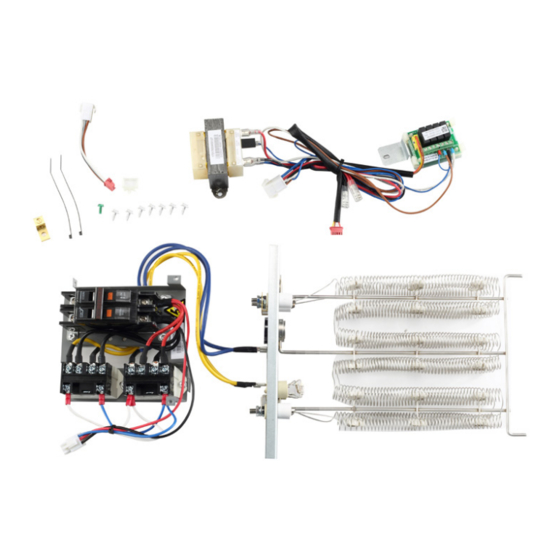
Shipping and Packing List
Check the components for shipping damage. If you find any
damage, immediately contact the last carrier.
Package 1 of 1 contains the following:
1 - Assembled electric heat coil assembly including breaker
1 - 24VAC transformer and relay assembly
1 - Grounding terminal
1 - Grounding screw
2 - Long screws (used to install transformer)
3 - Short screws (used to install circuit breaker panel and
relay)
2 - Plastic wire ties
1 - Plastic wire clamp
1 - wiring diagram sticker
1 - Installation/Operations manual
Requirements
Installation of electric heat sections must conform with
standard in National Fire Protection Association (NFPA)
Standard for Installation of Air Conditioning and Ventilation
Systems NFPA No. 90A, Standard for the Installation of
Residence Type Warm Air Heating and Air Conditioning
System
NFPA No.
instructions and local municipal building codes. Heaters are
approved for clearance to combustible materials as listed
on heater rating plate. Accessibility and service clearances
must take precedence over fire protection clearances. All
wiring must conform with local codes and the National
Electric Code (NEC). ANSI−C1−1978.
!
As with any mechanical equipment, contact with
sharp sheet metal edges can result in personal injury.
Take care while handling this equipment and wear
gloves and protective clothing.
1
90B,
manufacturer's
CAUTION
installation
Advertisement

Related Manuals for Lennox V8EH0050P-1P


Summary of Contents for Lennox V8EH0050P-1P
- Page 1 INSTALLATION INSTRUCTIONS ©2019 Lennox Industries Inc. Dallas, Texas, USA Electric Heat Kit for VVC* Vertical Air Handler VRF SYSTEMS -- V8EH-1P Series Electric Heat Kit 507567-04 01/2019 General The V8EH-1P series electric heat kits are used with VRF VVC****H4-1P/2P and 3P indoor units.
- Page 2 Installation IMPORTANT! 4. Lay the panel horizontal inside of the control box to allow for room to install the heat kit. See Figure 3. This heat kit includes a transformer and relay assembly. The transformer is factory-wired for 240V. For 208V, remove the red lead from the 240V terminal and connect it to the 208V terminal on the transformer.
- Page 3 7. Position the transformer on the back of the control box and secure with the two long screws. See Figure 6. Figure 9. Heat Kit Connected to L1 & L2 10. Connect the red plug to the appropriate connection point on the indoor unit’s main board, see table below. Figure 6.
- Page 4 Figure 16. element in a later step. See Figure 13. NOTE - For V8EH0050P-1P, V8EH0080P-1P and V8EH0100P-1P, remove only one panel. Figure 13. Remove Heat Kit Access Panel 12. Align the electric heat kit with the air handler unit and slide the heating element into the heat kit opening.
- Page 5 18. Use the provided plastic wire clamp to secure of the breaker panel to 19. Connect the white plug the wires between the heater elements and the the white connector of the transformer and breaker panel to the top of the main control board relay assembly.
- Page 6 See Figure 20. 7. Confirm that the total amp draw of the new heater NOTE - For V8EH0050P-1P, V8EH0080P-1P and kit does not exceed Minimum Circuit Ampacity for V8EH0100P-1P, remove only the left knockout.
- Page 7 Blower Speed Blower Motor Minimum Maximum Input Description Full Load Circuit Overcurrent Medium High Amps Ampacity Protection Volt Btuh 5 kW V8EH0050P-1P (13P59) 208 12,800 26.8 • • • 14,300 27.8 • • • 15,700 28.8 • • • 17,100 29.8...
- Page 8 Input Blower Motor Minimum Maximum Blower Speed Description Full Load Circuit Overcurrent Volt Btuh Medium High Amps Ampacity Protection 5 kW V8EH0050P-1P (13P59) 208 12,800 28.3 ⁴30 • • • 14,300 29.3 ⁴30 • • • 15,700 30.3 • •...
- Page 9 Blower Speed Blower Motor Minimum Maximum Input Description Full Load Circuit Overcurrent Medium High Amps Ampacity Protection Volt Btuh 5 kW V8EH0050P-1P (13P59) 208 12,800 24.5 • • • 14,300 25.5 • • • 15,700 26.5 • • • 17,100 27.5...
- Page 10 Blower Speed Blower Motor Minimum Maximum Input Description Full Load Circuit Overcurrent Medium High Amps Ampacity Protection Volt Btuh 5 kW V8EH0050P-1P (13P59) 208 12,800 26.8 • • • 14,300 27.8 • • • 15,700 28.8 • • • 17,100 29.8...
- Page 11 Input Blower Motor Minimum Maximum Blower Speed Description Full Load Circuit Overcurrent Volt Btuh Medium High Amps Ampacity Protection 5 kW V8EH0050P-1P (13P59) 208 12,800 28.3 • • • 14,300 29.3 • • • 15,700 30.3 • • • 17,100 31.3...
- Page 12 Load Volt Btuh Ckt 1 Ckt 2 Ckt 1 Ckt 2 Circuit Overcurrent Low Medium High Amps Ampacity Protection 5 kW V8EH0050P-1P 12,800 30.2 - - - - - - - - - - - - • • • (13P59) 14,300 31.2...
- Page 13 Load Volt Btuh Ckt 1 Ckt 2 Ckt 1 Ckt 2 Circuit Overcurrent Low Medium High Amps Ampacity Protection 5 kW V8EH0050P-1P 12,800 30.5 - - - - - - - - - - - - • • • (13P59) 14,300 31.5...
-
Page 14: Wiring Diagrams
Wiring Diagrams Figure 25. 5kW Wiring Diagram V8EH0050P1P Figure 26. 7.5 and 10kW Wiring Diagram V8EH0080P1P V8EH0100P1P... - Page 15 Figure 27. 15kW Wiring Diagram V8EH0150P1P Figure 28. 20kW Wiring Diagram V8EH0200P1P...
- Page 16 Technical Support 1-844-GET-VRF1 (1-844-438-8731) vrftechsupport@lennoxind.com www.LennoxVRF.com Download the app from the Apple App Store or the Google Play store.