Table of Contents
Advertisement
Quick Links
©2019 Lennox Industries Inc. Dallas, Texas, USA
THIS MANUAL MUST BE LEFT WITH THE OWNER
FOR FUTURE REFERENCE
These instructions are intended as a general guide and do
not supersede local codes in any way. Consult authorities
having jurisdiction before installation.
WARNING
Improper installation, adjustment, alteration, ser
vice or maintenance can cause property damage,
personal injury or loss of life.
Installation and service must be performed by a li
censed professional HVAC installer, service agency
or the gas supplier.
Failure to follow safety warnings and these instruc
tions exactly could result in property damage, dan
gerous operation, serious injury, or death.
Any additions, changes, or conversions required in
order for the appliance to satisfactorily meet the ap
plication needs must be made by a licensed profes
sional HVAC installer (or equivalent) using factory
specified parts.
Do not use this system if any part has been under
water. A flood-damaged appliance is extremely dan-
gerous. Immediately call a licensed professional
HVAC service technician (or equivalent) to inspect
the system and to replace all controls and electrical
parts that have been wet, or to replace the system, if
deemed necessary.
CAUTION
As with any mechanical equipment, contact with sharp
sheet metal edges can result in personal injury. Take
care while handling this equipment and wear gloves and
protective clothing.
To ensure proper system performance and reliability,
Lennox does not recommend operation of VRF sys-
tems during any phase of construction. Construction
debris, low temperatures, harmful vapors, and opera-
tion of the unit with misplaced filters can damage the
units. Failure to follow these guidelines will result in the
warranty being voided.
VRF
1
INSTALLATION
INSTRUCTION
VOSB Outside Air Ducted Units
VRF SYSTEMS -- Indoor Units
507896-02
06/2019
IMPORTANT
The Clean Air Act of 1990 bans the intentional venting
of refrigerant (CFC's and HCFC's) as of July 1, 1992.
Approved methods of recovery, recycling or reclaiming
must be followed. Fines and/or incarceration may be
levied for non-compliance.
General
The VOSB outside air ducted indoor units are matched
with an outdoor heat recovery or heat pump unit to
create a VRF (variable refrigerant flow) system that uses
R-410A refrigerant. VOSB indoor units are designed for
indoor installation only.
Refer to the Product Specification bulletin (EHB) for
the proper use of these indoor units with specific heat
pumps, heat recovery units, mode switching devices,
branch pipes, line sets and controls.
Shipping and Packing List
Check the components for shipping damage. If you find
any damage, immediately contact the last carrier.
Package 1 of 1 contains the following:
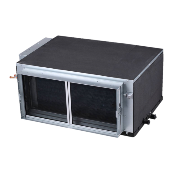
1 - Assembled high-static, concealed duct unit
1 - Digital Display Panel
2 - Refrigerant piping insulation sleeves
1 - Flexible condensate connector (VOSB036-054)
1 - Hose clamp (VOSB036-054)
1 - Condensate connection pipe (VOSB072-096)
(Packed in Supply side of cabinet.)
1 - Roll tape for condensate pipe (VOSB072-096)
1 - Condensate overflow connection harness
1 - 120 Ohm End of Line Resistor
1 - Installation manual
Advertisement
Table of Contents

Related Manuals for Lennox VOSB Series


Summary of Contents for Lennox VOSB Series
- Page 1 To ensure proper system performance and reliability, Lennox does not recommend operation of VRF sys- tems during any phase of construction. Construction debris, low temperatures, harmful vapors, and opera- tion of the unit with misplaced filters can damage the units.
-
Page 2: Safety Requirements
NOTE - Only Lennox VRF indoor units will work with Lennox VRF outdoor units and associated mechanical equipment. Lennox Mini Split indoor units are similar in appearance but must not be connected to a Lennox VRF refrigerant circuit. Please refer to model numbers to confirm compatibility. Model numbers for Lennox VRF units start with a “V”... -
Page 3: Unit Dimensions Inches (Mm)
Unit Dimensions Inches (mm) VOSB036, 048, 054 SECTION A-A BRACKETS FOR SUSPENDING (4) 45-1/4 (1149) 5-3/8 3-5/8 (92) PRIMARY 7-1/4 (137) DRAIN (184) CONNECTION 29-1/8 (Either Side) 25-1/8 (740) LIQUID PIPE (638) AUXILIARY 15-5/8 GAS PIPE DRAIN (397) CONNECTION ELECTRICAL (Either Side) CONTROL... - Page 4 Unit Dimensions Inches (mm) VOSB072, 096 SECTION A-A BRACKETS FOR 50 (1270) SUSPENDING (4) PIPE LIQUID PIPE 38-1/4 34-5/8 (972) (879) 12-1/8 ELECTRICAL (308) CONTROL TOP VIEW SECTION C-C SUPPLY TOP OF UNIT (Supply Air RETURN AIR DUCT GAS PIPE Duct Opening) AIR DUCT OPENING...
- Page 5 Clearances Refer to Figure 1 for minimum clearance requirements. Wall 20” (508 mm) Minimum Service Clearance DUCTED UNIT Flow Minimum Service 24” (610 mm) Wall Clearance 24” (610 mm) Minimum Service Clearance TOP VIEW Ceiling 24” (610 mm) Minimum Clearance 1”...
-
Page 6: Unit Placement
Unit Placement AVOID WARNING Do not install the unit in the following locations: Do not install the unit in an area where flammable • Areas near commercial kitchen exhaust hoods where materials are present due to risk of explosion resulting odors and grease may enter the air stream. -
Page 7: Installation
NOTE - Threaded rod (requirement height. Remove the electrical tape holding the upper of Lennox warranty program) is the ONLY acceptable washers and nuts in place and tighten each of the four method of suspending the unit; do not use chains or nuts above the brackets down onto the brackets. - Page 8 Return Air Filter Return Air Filter 2. Grasp the filter removal tab and slide the filter out. The factory-supplied return air filter is segmented to allow it to be separated if needed to remove it from the unit in tight spaces. The segments are connected with hook & loop (Velcro-style) straps.
-
Page 9: Refrigerant Piping Connections
Refrigerant Piping Connections WARNING IMPORTANT Refrigerant lines must be clean, dry, refrigerant-grade Refrigerant leaks are unlikely; however, if a refrigerant copper lines. Air handler coils should be installed leak occurs, open a door or windows to dilute the only with specified line sizes for approved system refrigerant in the room. -
Page 10: Liquid Line
• Refrigerant lines must be connected by a qualified 1. The seal on the unit refrigerant piping connections technician in accordance with established procedures. should remain in place until the last possible moment. This will prevent dust or moisture from getting into the •... - Page 11 Condensate Piping Connections 3. See Figure 10 for applications including a single unit VOSB036054 indoor units have a factory-installed and a single gravity drain. In this case, ensure that condensate lift pump capable of 28 inches (711 mm) of lift the drain line is properly sloped (no less than 1/4 inch and one gravity drain connection on each side of the unit.
- Page 12 Table 3. Condensate Pump Accessory Options Max Flow Capacity Brand Model Name Model # Cat # Rate suction head (gal per hr) lift* Lennox VRF Drain Pump Kit V8DRNP05 17U32 18 in VOSB072-096 Blue MegaBlue X87-835 14T71 13.2 66.5 ft 23 ft Diamond *Optional pump maximum suction lift is measured from the pump outlet.
-
Page 13: Wiring Connections
Table 4. Condensate Connection Sizes Condensate Condensate Condensate Pump Condensate Flexible Drain Con Life Pump Model Pump Lift Facility on Indoor Outlet of nection (supplied Factory Measurement PCB Board Indoor Unit with unit) Mounted 1” O.D. VOSB Outside Air Yes - 036-054 1-5/8”... - Page 14 1. Remove the screws that secure the control box cover. Indoor units and mode selection boxes on the same Remove the cover and place it to the side where it will refrigeration circuit should have a common power not be damaged. supply but must have an independent disconnect switch installed adjacent to each item of equipment for servicing 2.
- Page 15 Outdoor unit Outdoor unit Outdoor unit (sub1 unit) (main unit) (sub2 unit) H1 H2 Outdoor Unit Communication Terminal Block (H1 H2 (H1 H2 (H1 H2 (PQ) (PQ) (PQ) (PQ) MS Box Communication Terminal Block HA HB 12V COM P (PQ) (PQ) Indoor Unit Communication Terminal Block Ground drain wire or...
- Page 16 Outdoor unit Outdoor unit Outdoor unit (main unit) (sub1 unit) (sub2 unit) (H1 H2 (H1 H2 (H1 H2 H1 H2 Outdoor Unit Communication Terminal Block (PQ) HA HB 12V COM P Indoor Unit Communication Terminal Block Ground cable shield (PQ) to Indoor Unit chassis Install a terminating resistor (Ω120) at the last indoor unit terminals P and Q of the daisy chain.
-
Page 17: Main Board
Error code Error Content Error code Error Content Title Code Title Code Mode conflict MS self-inspection error Indoor fan motor XS1-5 Connectors MS error Communication error between indoor and main outdoor unit Inlet air temperature sensor XT1-2 Terminals EEV malfunction T0 (Inlet air temperature sensor) malfunction Inlet of evaporator sensor PUMP... -
Page 18: Dip Switch Setting
Error code Error Content Error code Error Content Title Code Title Code Mode conflict MS self-inspection error Indoor fan motor XS1-6 Connectors MS error Communication error between indoor and main outdoor unit XT1-2 Inlet air temperature sensor Terminals T0 (Inlet air temperature sensor) malfunction EEV malfunction Inlet of evaporator sensor PUMP... - Page 19 Relocate T0 Return Air Sensor Relocate the unit return air from inside the unit to a loca- tion within the conditioned zone whenever the return is pulling air from above the ceiling or if fresh air is being introduced and mixed into the return. The T0 sensor can- not accurately read the space temperature under these conditions if the sensor remains located inside of the unit.
- Page 20 Error code Error Content Error code Error Content Title Code Title Code Mode conflict MS self-inspection error Indoor fan motor XS1-5 Connectors MS error Communication error between indoor and main outdoor unit Inlet air temperature sensor XT1-2 Terminals EEV malfunction T0 (Inlet air temperature sensor) malfunction Inlet of evaporator sensor PUMP...
- Page 21 Mounting the Receiver/Display The VOSB unit receiver/display must be field-connected and mounted. Mounting slots are available on the bottom Cable path of the electrical control box. 1. Remove receiver from accessories package. 2. Insert the two fixed plastic mounting brackets on the back of the receiver (Figure 26) into the two slots on Slots the bottom of the electrical control box (Figure 25) and...
- Page 22 Spot Check Instructions Use the Spot Check Performance table below and the Manual button on the unit receiver to view diagnostic information the indoor unit. Table 7. Spot Check Performance Identification Table Content Recorded Value/Date Normal display Communication address of indoor unit Indoor unit capacity (horsepower) Network address of indoor unit The actual setpoint temperature...
-
Page 23: Troubleshooting
Troubleshooting Digital Display Make note of the code (E1, EE, etc.), then reset the display by pressing the ON/OFF button on the unit The indoor unit is equipped with a receiver that has a controller. Press the ON/OFF button a second time digital display that provides an error code. -
Page 24: Technical Support
Technical Support 1-844-GET-VRF1 (1-844-438-8731) vrftechsupport@lennoxind.com www.LennoxVRF.com Download the app from the Apple App Store or the Google Play store.