Table of Contents
Advertisement
Quick Links
Advertisement
Table of Contents

Related Manuals for Lennox VRF VEAH024C432P


Summary of Contents for Lennox VRF VEAH024C432P
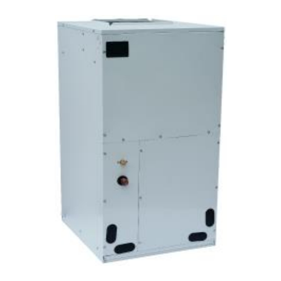
- Page 1 VRF Indoor Units Installation Manual Air Handler Fan Coil VEAH024C432P VEAH030C432P VEAH036C432P VEAH042C432P VEAH048C432P VEAH054C432P Thank you for selecting LENNOX air conditioners. Please read this manual carefully before operation and keep it for further reference.
- Page 2 Preface For correct installation and operation, please read all instructions carefully. Before reading the instructions, please be aware of the following items: (1) For the safe operation of this unit, please read and follow the instructions carefully. (2) During operation, total capacity of indoor units should not exceed the total capacity of outdoor units.
- Page 3 Exception Clauses Manufacturer will bear no responsibilities when personal injury or property loss is caused by the following reasons: (1) Damage the product due to improper use or misuse of the product; (2) Alter, change, maintain or use the product with other equipment without abiding by the instruction manual of manufacturer;...
-
Page 4: Table Of Contents
Contents 1 Safety Precautions .................... 1 2 Product Introduction ..................3 2.1 Names of Key Components ..................3 2.2 Rated Working Condition ..................3 3 Preparative for Installation ................4 3.1 Pre-Installation Instruction ..................4 3.2 Important Safety Instructions ..................4 3.3 Requirements for Communication Line .............. -
Page 5: Safety Precautions
(20) User is not allowed to repair the unit. Fault service may cause electric shock or fire accidents. Please contact LENNOX appointed service center for help. (21) Before installation, please check if the power supply is in accordance with the requirements specified on... - Page 6 (28) If anything abnormal happens (such as burning smell), please power off the unit and cut off the main power supply, and then immediately contact LENNOX appointed service center.If abnormality keeps going, the unit might be damaged and lead to electric shock or fire.
-
Page 7: Product Introduction
VRF DC Air Handler 2 Product Introduction 2.1 Names of Key Components Fig 2.1 2.2 Rated Working Condition Indoor Side Condition Outdoor Side Condition Dry Bulb Temp °C ( °F ) Wet Bulb Temp °C ( °F ) Dry Bulb Temp °C ( °F ) Wet Bulb Temp °C ( °F ) Rated Cooling 27(80.6) 19(66.2) -
Page 8: Preparative For Installation
VRF DC Air Handler 3 Preparative for Installation 3.1 Pre-Installation Instruction 3.1.1 Checking Product Received After receiving the product, please check if there is any damage caused by transportation. Shipping damage is the responsibility of the carrier. Verify the model number, specifications and accessories are correct prior to installation. - Page 9 VRF DC Air Handler WARNING: Before serving or installing this equipment. The electrical power to this unit must be in the “off” position. Caution, more than one disconnect may exist. Failure to observe this warning may result in an electrical shock that can cause personal injury or death. WARNING: The United States environmental protection agency (‘epa”) has issued various regulations regarding the introduction and disposal of refrigerants introduced into this unit.
-
Page 10: Requirements For Communication Line
VRF DC Air Handler from the exhaust emissions.If a furnace or air handler is installed in an enclosed area such as a garge, utility room or parking area and a carbon monoxide producing device is operated therein, there must be adequate ventilation directly to outside. This ventilation is necessary to avoid the danger of CO poisoning which can occur if a carbon monoxide producing device continues to operate in the enclosed area. -
Page 11: Wiring Requirements
VRF DC Air Handler 3.3.2 Select communication line for indoor unit and outdoor unit Fig 3.3.2 Total length of communication wire Wire diameter Wire type between indoor unit and Wire standard Remark (AWG) indoor unit(outdoor unit) (m/feet) (communication 1. If the wire diameter is line for indoor unit) enlarged to 18AWG, the Light/Ordinary... -
Page 12: Installation Instructions
VRF DC Air Handler Above selection requirements: Power cord size is based on BV single-core wire (2~4pc) at 40° (104°F) Cambient temperature when laying across plastic pipe. Air switch is D type and used at 40°C (104°F). If actual installation condition varies, please lower the capacity appropriately according to the specifications of power cord and air switch provided by manufacturer. -
Page 13: Location
VRF DC Air Handler 4.2 Location 4.2.1 Installation Site A place where cool air can be distributed throughout the room. A place where condensation water is easily drained out. A place that can bear the weight of indoor unit. ... -
Page 14: Piping Work
VRF DC Air Handler Fig 4.2 4.3 Piping Work 4.3.1 Specification of Connection Pipe External Diameter (inch) Model Gas Pipe(in) Liquid Pipe(in) VEAH024C432P VEAH030C432P VEAH036C432P VEAH042C432P VEAH048C432P VEAH054C432P 4.3.2 Piping Preparation All cut ends are to be round, burr free, and cleaned. Failure to follow this practice increases the chances for refrigerant leakage. -
Page 15: Condensate Removal
VRF DC Air Handler 4.4 Condensate Removal (1) It is not allowed to connect the condensate drain pipe into waste pipe or other pipelines which are likely to produce corrosive or peculiar smell to prevent the smell from entering indoors or corrupt the unit. (2) It is not allowed to connect the condensate drain pipe into rain pipe to prevent rain water from pouring in and cause property loss or personal injury. -
Page 16: Installation Of Wired Controller
VRF DC Air Handler 4.6 Installation of Wired Controller Please refer to User Manual of Wired Controller for the installation details. Note: When installation is finished, the unit must be tested and debugged before operation. Please refer to Instruction Manual of ODU for auto addressing and debugging details. -
Page 17: Power Cord Connection
VRF DC Air Handler Fig 5.1.1 Fig 5.1.2 5.2 Power Cord Connection NOTICE! All indoor units must be unified of power supply so that they can be powered ON/OFF at the same time. Fig 5.2 ● For units with single-phase power supply. (1) Detach the electric box lid. -
Page 18: Connect Communication Wire Of Wired Controller
VRF DC Air Handler (4) Fix the communication cable with clamp of electric box. (5) For more reliable communication, make sure connect the terminal resistor to the most downstream IDU of the communication bus (terminal D1 and D2), as shown in fig 5.3.2, terminal resistor is provided with each ODU. - Page 19 VRF DC Air Handler Fig 5.5...
-
Page 20: Routine Maintenance
VRF DC Air Handler 6 Routine Maintenance Do turn off the unit and cut off the main power supply when cleaning the air conditioner to avoid electric shock or injury. Stand at solid table when cleaning the unit. Do not clean the unit with hot water whose temperature is higher than 45°C to prevent fade or deformation. -
Page 21: Table Of Error Codes For Indoor Unit
VRF DC Air Handler 7 Table of Error Codes for Indoor Unit Error Error Error Content Content Content Code Code Code Quantity Of Group Control Water Temperature Sensor Indoor Unit Error Indoor Units Setting Error Error Indoor Fan Indoor Units Incompatibility Jumper Cap Error Protection Error... - Page 22 Contact us at +1-305-718-2901 lennoxglobalhvac@lennoxintl.com 2018 Lennox Industries Inc. For a complete list of the registered and common law trademarks owned by Lennox Industries Inc., please visit www.lennox.com...