Lennox CBX25UH Installation Instructions Manual
Merit series
Hide thumbs
Also See for CBX25UH:
- Installation and service procedure (22 pages) ,
- Installation and service procedure (23 pages) ,
- Installation instructions manual (16 pages)
Advertisement
E2016 Lennox Industries Inc.
Dallas, Texas, USA
THIS MANUAL MUST BE LEFT WITH THE
HOMEOWNER FOR FUTURE REFERENCE
WARNING
Improper installation, adjustment, alteration, service or
maintenance can cause personal injury, loss of life, or
damage to property.
Installation and service must be performed by a licensed
professional installer (or equivalent) or a service agency.
IMPORTANT
The Clean Air Act of 1990 bans the intentional venting of
refrigerant (CFCs, HCFCs and HFCs) as of July 1, 1992.
Approved methods of recovery, recycling or reclaiming
must be followed. Fines and/or incarceration may be
levied for noncompliance.
IMPORTANT INFORMATION FOR INSTALLER
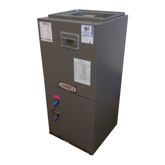
This unit has a delay relay that delays the supply blower "ON" for 1 second and keeps the blower "ON" for 45
seconds on all fan and cooling demands. For more details, refer to page 17 for unit sequence of operation.
100%
2
1
CFM
1
SECOND
COOLING
DELAY
DEMAND
Page 1
INSTALLATION
INSTRUCTIONS
®
Merit
CBX25UH (-10) Series
Units
AIR HANDLERS
507600-03
9/2016
Shipping and Packing List
Package 1 of 1 contains the following:
1 - Assembled air handler unit factory-equipped for
upflow or horizontal air discharge application (includes
upflow and horizontal drain pans and pre-installed air
filter).
Check equipment for shipping damage. If found,
immediately report damage to the last carrier. Check the
unit rating plate to confirm that delivered unit matches
order.
General
The CBX25UH air handler is designed for indoor
installation only. As shipped, the unit is ready for
installation in either upflow, horizontal left-hand or
right-hand air discharge applications. Electric heat,
downflow air discharge kits, air filters and other
accessories are available and listed in the CBX25UH
Product Specification bulletin for ordering.
All
units
are
shipped
check/expansion valve.
WARNING
This product contains a chemical known to the State of
California to cause cancer, birth defects, or other repro
ductive harm.
3
4
100%
CFM
OFF
45
SECS
with
a
factory-installed
Advertisement
Table of Contents

Related Manuals for Lennox CBX25UH


Summary of Contents for Lennox CBX25UH
- Page 1 HOMEOWNER FOR FUTURE REFERENCE order. General WARNING The CBX25UH air handler is designed for indoor installation only. As shipped, the unit is ready for Improper installation, adjustment, alteration, service or installation in either upflow, horizontal left-hand or maintenance can cause personal injury, loss of life, or right-hand air discharge applications.
- Page 2 CBX25UH Unit Dimensions – Up-flow – inches (mm) 52-1/2 Page 2...
- Page 3 Ac of Lennox air handler units (with or without optional electric cessibility and service clearances must take precedence heat), MUST conform with National Fire Protection over combustible material clearances.
- Page 4 UPFLOW (BOTH SIDES; NOT DRAIN PAN USED) When a CBX25UH unit is installed in a closet with a louvered return opening, the minimum open area for the UPFLOW DRAIN louvers will be: CONNECTIONS (BOTH SIDES; USE ONE SIDE 320 square inches for -018 and -024 models;...
- Page 5 Reinstall the top cap. Rotate the blow-off prevention brackets 180º and reinstall using the same screws. Use the correct mounting holes; the Figure 4. Remove Main Drain Pan Mounting Brackets brackets must cover the hairpins. See figure 7. Page 5 CBX25UH SERIES...
- Page 6 7. Reinstall the brackets that hold the coil and horizontal drain pan in place. See figure 9. Figure 7. Reinstall the Top Cap. Brackets Must Cover the Hairpins 6. Slide coil assembly, bottom drain pan and horizontal drain pan as one unit back into the air handler. Figure 9.
-
Page 7: Condensate Drain
TRAPS MUST BE DEEP ENOUGH TO OFFSET MAXIMUM STATIC DIFFERENCES — GENERALLY, TWO INCHES (51MM). TRAP DEPTH TO APPROVED LENNOX P-TRAP 49P66 REQUIRES A LARGER INSTALLATION SPACE THAN THE J-TRAP 91P90. DRAIN FOR NEGATIVE PRESSURE COILS (BLOWER DRAIN LINE SHOULD PIPE NIPPLE PROVIDED IN BAG ASSEMBLY - SCH 80, 3/4”... -
Page 8: Install Condensate Drain
Confirm primary and secondary drains are open. positive drainage without a proper trap. 1. CBX25UH units are equipped with a drain pan, which 7. Route the drain line to the outside or to an appropriate includes green (main drain) and red (secondary drain) drain. - Page 9 Before using any filter with this system, check the spe cifications provided by the filter manufacturer against the data given in the appropriate Lennox Product Specifica Figure 13. Cabinet and Duct Flange tions bulletin. Additional information is provided in Ser...
- Page 10 NOTE - When installing refrigerant lines longer than 50 WARNING feet, see the Lennox Refrigerant Piping Design and Fabrication Guidelines, CORP. 9351-L9, or contact Danger of fire. Bleeding the refrigerant Lennox Technical Support Product Applications for charge from only the high side may result assistance.
- Page 11 REMOVE ACCESS PANEL REMOVE RUBBER PLUG FROM BOTH LIQUID AND SUCTION LINES NOTE - CBX25UH SERIES UNITS USE NITROGEN OR DRY AIR AS A HOLDING CHARGE. IF THERE IS NO PRESSURE WHEN THE RUBBER PLUGS ARE REMOVED, CHECK THE COIL FOR LEAKS BEFORE INSTALLING.
-
Page 12: Sealing The Unit
Sealing the Unit WARNING Seal the unit so that warm air is not allowed into the Electric Shock Hazard. cabinet. Warm air introduces moisture, which results in Can cause injury or death. water blow-off problems. This is especially important when Foil‐faced insulation has conductive characteristics sim... -
Page 13: Use Copper Conductors Only
NOTE - To avoid the possibility of moisture damage to the control in some right-hand discharge configurations, the control panel can be relocated to the end panel as shown in figure 16. Figure 17. Converting Unit from 240 VAC to 208 VAC Page 13 CBX25UH SERIES... - Page 14 # FACTORY SPEED SET TO MEDIUM (BLUE) FOR -018, -024, -030, -036, PLUG GROUND LUG -042, AND -060. FACTORY SPEED SET TO LOW (RED) FOR -048 WARNING USE COPPER CONDUCTORS ONLY Figure 18. Typical Wiring Diagram — CBX25UH Air Handler with Electric Heat Page 14...
-
Page 15: Air Flow - Cooling Blower Speed
NOTE - Reuse the factory-installed wire nut on the Replace all parts and panels before oper unused wires. ating. 5. Replace all panels. Failure to do so can result in death or elec trical shock. 6. Reconnect power. Page 15 CBX25UH SERIES... - Page 16 YELLOW (COM) with a dry DX coil. 4-PIN BLOWER CONNECTOR Figure 20. Changing Blower Speed Table 2. CBX25UH Blower Performance (3-Speed PSC) - 240V (CFM @ ESP. - in. W. C.) Air Handler Blower Speed .10" WC .20" WC .30" WC .40"...
- Page 17 Circuit R-W1 energizes a heat and auxiliary heat should come on together. Allow a sequencer. completed circuit will energize minimum of 3 minutes for all sequencers to cycle on. supplemental electric heat (if applicable). Units with a Page 17 CBX25UH SERIES...
-
Page 18: Emergency Heat (Heating Heat Pump)
Use of Air Handler During Construction If water is seen dripping from the secondary drain line, Lennox does not recommend the use of its air handler unit contact a qualified service technician. This is a sign of during any phase of construction. Very low return air a problem which must be investigated and corrected. - Page 19 Electrial Connections Tight THERMOSTAT DRAIN LINE Adjusted and Programmed Leak Free Operation Explained to Owner Explained Operation of System to Homeowner Technician’s Name:_______________________Date Start−Up & Performance Check Completed__________ Figure 23. Start-Up and Performance Checklist (Upflow Configuration) Page 19 CBX25UH SERIES...
- Page 20 Installing Contractor’s Name_______________________ Installing Date_______________________________ Installing Contractor’s Phone_______________________ Air Handler Model #___________________________ Job Address____________________________________ Line Voltage Disconnect Switch Thermostat Integrated Control Duct System Duct System Filter RETURN SUPPLY Electric Heat Amps Blower motor Amps Drain Line Duct Static Temperature DUCT SYSTEM TOTAL EXTERNAL STATIC (dry coil) dry coil wet coil...